Numerical Analysis of Thermal Convection in a CPU Chassis
←
→
Page content transcription
If your browser does not render page correctly, please read the page content below
Open Journal of Modelling and Simulation, 2021, 9, 43-58
                                                                                             https://www.scirp.org/journal/ojmsi
                                                                                                           ISSN Online: 2327-4026
                                                                                                             ISSN Print: 2327-4018

Numerical Analysis of Thermal Convection in a
CPU Chassis

M. Z. I. Bangalee1,2*, Md. Mizanur Rahman1,2, M. Ferdows1,2, M. S. Islam3
1
  Department of Applied Mathematics, University of Dhaka, Dhaka, Bangladesh
2
  Research Group of Fluid Flow Modeling and Simulation, Department Applied Mathematics, University of Dhaka, Dhaka,
Bangladesh
3
  Department of Mathematics, University of Dhaka, Dhaka, Bangladesh

How to cite this paper: Bangalee, M.Z.I.,       Abstract
Rahman, Md.M., Ferdows, M. and Islam,
M.S. (2021) Numerical Analysis of Thermal       Flow distribution and the effects of different boundary conditions are
Convection in a CPU Chassis. Open Journal       achieved for a steady-state conjugate (Conduction & Convection) heat trans-
of Modelling and Simulation, 9, 43-58.
                                                fer process. A plate fin heat sink with horizontal fin orientation along with a
https://doi.org/10.4236/ojmsi.2020.91003
                                                computer chassis is numerically investigated and simulated using software
Received: September 17, 2020                    ANSYS CFX. Fin orientation of a heat sink changes the direction of fluid flow
Accepted: January 12, 2021                      inside the chassis. For predicting turbulence of the flow inside the domain, a
Published: January 15, 2021
                                                two-equation based k-ε turbulence model is chosen. The Reynolds number
Copyright © 2021 by author(s) and               based on inflow velocity and geometry is found 4.2 × 10³ that indicates that
Scientific Research Publishing Inc.             the flow is turbulent inside the chassis. To get proper thermal cooling, the op-
This work is licensed under the Creative
                                                timum velocity ratio of inlet/outlet, dimension of inlet/outlet and different
Commons Attribution International
License (CC BY 4.0).                            positions of outlet on the back sidewall of the chassis are predicted. Aspect
http://creativecommons.org/licenses/by/4.0/     velocity ratio between the inlet airflow and the outlet airflow has an effect on
               Open Access                      the steadiness of the flow. Mass flow rate depends on the dimension of the
                                                inlet/outlet. The horizontal fin orientation with 1:1.6 inlet-outlet airflow ve-
                                                locity ratio gives better thermal performance when outlet is located at the top
                                                corner of the chassis, near to the inner sidewall. Flow distribution and heat
                                                transfer characteristics are also analyzed to obtain the final model.

                                                Keywords
                                                Reynolds Number, Turbulence Model, Heat Sink, CPU Chassis, Conduction,
                                                Convection

                                              1. Introduction
                                              An Integrated Circuit (IC) is a small semiconductor chip usually made of silicon.

DOI: 10.4236/ojmsi.2020.91003 Jan. 15, 2021                        43                    Open Journal of Modelling and Simulation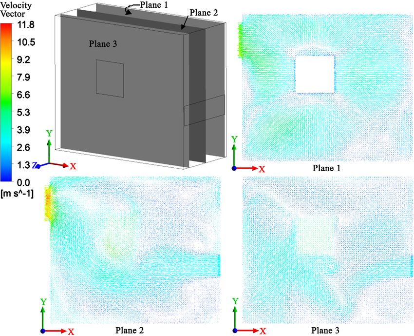
M. Z. I. Bangalee et al.

                                It can contain thousands to millions of diodes, transistors, resistors and capacitors.
                                These small electronics can perform calculations and store data using either digital
                                or analog technology. When an IC is used to control the whole computer system is
                                known as Central Processing Unit (CPU) or simply processor. It is the most inter-
                                esting piece of hardware system and considered as the brain of a microcomputer.
                                In modern microcomputers, the processor is square inch or so in size.
                                   The CPU is responsible for processing most of the data within the computer
                                system. That’s why CPU generates a great deal of undesirable heat in modern
                                computing system. When the data is processed, heat is generated. Once heat
                                threshold is exceeded, CPU is placed at a risk of malfunction or permanent
                                damage [1]. At the very beginning, processors were able to operate safely with-
                                out heat removal system. The first Intel processors were already producing
                                considerable amount of heat but low specification allowed operation without any
                                heat removal mechanism [2]. At the present time, as the processor speed in-
                                creased, these processors are going to generate a large amount of heat, for exam-
                                ple, Intel core i7 7700k dissipate 91 W of heat within the area of 37.5 mm × 37.5
                                mm [3]. Therefore, a heat removal system with proper boundary conditions is
                                obvious for these processors.
                                  Many researchers have worked on air based heat sink where a cooling fan is
                                necessary. This is very common approach for cooling personal computers.
                                However, many liquids based heat sinks are also available. An isolated chip dis-
                                sipating 100 w could be cooled by forced-air convection [4]. Tuckerman and
                                Pease [4] designated and tasted a very compact; water cooled integral heat sink
                                for silicon integrated circuit. A 50 µm wide and 300 µm deep micro channel heat
                                sink is capable of dissipating a power density of 790 W/cm2 with a junction
                                temperature of 71˚C. Heat sink combined with heat pipe and cooling fan were
                                investigated at different times [5] [6] [7] [8] to improve thermal management of
                                Laptop and personal computers. Heat sink together with cooling fan is also stu-
                                died at different times to cool the heated component in computer chassis. Yuji et
                                al. [9] studied fan heat sink cooling technology for laptop, desktop and several
                                applications. Stafford et al. [10] investigate flat plate heat transfer with axial fan
                                flows. Zheng [11] made a simulation for cooling fan.
                                  Low power dissipating CPU can be cooled by natural convection without
                                cooling fan. The driving force for natural convection is gravity. Mousavi et al.
                                [12] investigate the natural convection and radiation heat transfer from vertical
                                heat sinks with various configurations of fins to find the preferred design among
                                the investigated cases and present the result in the form of streamline, velocity
                                magnitudes, temperature contours, mean Nusselt numbers, average temperature
                                of heat sinks and the radiation to total heat transfer ratio. As modern CPU can
                                be placed at a risk of malfunction for natural convection. Shi et al. [13] present a
                                method of designing an air heat sink with force convection by topological opti-
                                mization. This method requires lower pumping power when compared others.
                                They evaluated both pressure drop and heat transfer performances. The opti-

DOI: 10.4236/ojmsi.2020.91003                         44                     Open Journal of Modelling and Simulation
M. Z. I. Bangalee et al.

                                mized structure is manufactured and experimentally validated. In forced con-
                                vection, mass flow rate inside the chassis, aspect velocity of inlet/outlet and the
                                position of outlet has an effect on CPU cooling.
                                   Jeffrey P. Koplow [14] introduced new approaches to air-cooled heat ex-
                                changers without using the conventional air-cooled heat exchanger. This first
                                prototype device was designed for an electronics cooling application. For heat
                                exchanger approach Staats and Barisson [15] present an air cooled heat sink us-
                                ing integrated centrifugal fans in which fan blades are placed in close proximity
                                to the heated surface where the air only entered into the top axial inlet and
                                heated air is pumped radially outward. In this research they experimentally stu-
                                died the fan curves, power consumption of planner and the heat transfer in this
                                integrated fan system. Chao et al. [16] numerically investigate the thermal design
                                of rack cooling system with pulsating heat pipe in data center and compare with
                                experimental. In order to simplify the theoretical model turbulent flow is consi-
                                dered into the rack and molecular viscosity is neglected. In this research, turbu-
                                lent flow is also considered and viscosity is neglected for forced convection air
                                cooling method.
                                  Computational fluid Dynamics (CFD) is a technique for solving governing
                                equations of fluid dynamics and heat transfer numerically with the help of
                                computers. It is also known as flow simulation or computer simulation. Flow
                                pattern and heat transfer characteristics can easily be predicted using this tech-
                                nique. Therefore, it is very popular and widely used. Yabo et al. [17] predicted
                                different positions of outlet numerically. Prajapati [18] studied heat transfer and
                                fluid flow behavior numerically in rectangular parallel micro channel heat sinks
                                by varying fin height. Yunke Zhong et al. [19] carried out simulated results to
                                study the flow and heat transfer characteristics of mist in a wire rod bundle.
                                They discussed the turbulent flow behavior and the heat transfer performance of
                                post-CHF (critical heat flux) mist flow in the rod bundle.
                                  During its operation the CPU dissipates heat that makes the air warmer inside
                                the chassis. Eventually, warmer air needs to be replaced with cooler air for sav-
                                ing the CPU from overheating. In this cooling cycle the aspect ratio of the inlet
                                and the outlet plays an important role. Since the air flows in two directions in-
                                side the fin channel, this study considers a plate fin heat sink. Furthermore, de-
                                pending on the heat sink fin orientation, the outlet position is tested and discussed
                                to analyze the cooling effect. A velocity ratio between the inlet air flow and the
                                outlet airflow is also considered as the outlet airflow also come out by the force.
                                Since the present study involves a variety of geometry modifications, this study
                                takes the advantages of computational approach. It is obvious that the computa-
                                tional approach with the help of technologies can deal with a myriad amount of
                                cases and data with comparatively less efforts. The flow and the temperature
                                distributions are predicted using ANSYS CFX [20] for different geometry and
                                the relevant boundary conditions. The numerical methodology is verified satis-
                                factorily after applying the methodology to resimulate some published cases.

DOI: 10.4236/ojmsi.2020.91003                         45                     Open Journal of Modelling and Simulation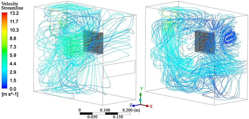
M. Z. I. Bangalee et al.
2. Description of the Model
Computational domain in the present work is a heat sink along with a normal
size of CPU chassis. The chassis has 395 mm length, 180 mm width and 340 mm
height. It has six sidewalls mentioned in Figure 1 where the inner sidewall is laid
on the xy plan. It has inlet on the outer sidewall, outlet on the back sidewall and
85 cm2 opening area on the front sidewall. Inlet is located at the opposite of the
heat sink as it can blow air directly toward the heat sink, outlet blows air outside
of the chassis and opening balances the air pressure gradient inside the chassis.
A rectangular fin heat sink is placed on the top of the processor which is located
on the inner sidewall. The dimension of the heat sink is 85 mm × 85 mm × 25
mm with 1 mm width fin. Fins are horizontally oriented. The model in the
present work is drawn by software CATIA [21] shown in the following Figure 1.
3. Numerical Method
The following steps are followed to simulate the problem of the system numeri-
cally:
3.1. Governing Equations, Boundary Conditions
and Numerical Solution
The instantaneous equation of mass, momentum and energy conservation can
be written in the following form.
Conservation of mass
∂
∂x j
(U=
j) 0;=j 1, 2,3
Conservation of momentum
∂ ∂p ∂ ∂U i
ρU j
xj
(Uj)= + ( µ + µt )
∂xi ∂x j
+ ρ0 gi β (T − T0 ) ; i =
∂x j
1, 2,3 & j =1, 2,3
Figure 1. Computational geometry (CPU chassis).
DOI: 10.4236/ojmsi.2020.91003 46 Open Journal of Modelling and Simulation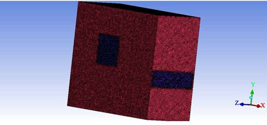
M. Z. I. Bangalee et al.
Conservation of energy
∂ ∂ υ υt ∂T
Uj (T ) = + ; j =
1, 2,3
∂x j ∂x j Pr σ t ∂x j
Equation of state
p = ρ RT
µC p
In these equations U is the velocity vector. pr = is the prandtl number,
k
p is the air static pressure, µ is the air viscosity, υ is the kinematic viscosity,
k is the thermal conductivity, gi is the gravitational acceleration, R is the ideal
gas constant, ρ is the density of air at temperature T and ρ0 is the density of
air at temperature T0 . The Bousinessq approximation ρ0 gi β (T − T0 ) is used
in the momentum equation to model the buoyancy force. The transport equa-
tion for k-ε turbulence model is given below,
∂ ∂ µt ∂k
The k equation, ρ
∂x j
( jk )
U= µ +
∂x j
+ Pk − ρε
σ k ∂x j
∂ µt ∂ε ε
The ε equation, ρ
∂x j
(U j ε ) = ∂∂x µ +
σε
+ ( Cε 1 Pk − Cε 2 ρε )
j ∂x j k
where the turbulence viscosity µt is linked to the turbulence kinetic energy (k)
and dissipation (ε) via the relation
k2
µt = C µ ρ ;
ε
where Cµ is constant.
Assuming steady state three dimensional flow inside the chassis all of the go-
verning equations need to be solve and in the solid domain only energy equation
needs to be solved. The property of air at 25˚C and 1 atm are considered inside
the chassis. All of the flow regimes are subsonic and the airflow is assumed
buoyant. Heat transfer is initiated due to thermal energy. Other boundary condi-
tions are:
u 0 m ⋅ s −1 , =
1) Inlet: = v 0 m ⋅ s −1 , =
w 5 m ⋅ s −1 ,
−1
2) Outlet: =
u 8 m ⋅s , v = 0 , w = 0 ,
3) Opening: Opening pressure and direction with relative pressure 0 pa and
opening temperature is set at 25˚C,
4) Heat flux: 64,711 Wm2
A CFD software, ANSYS CFX-Solver Manager is used to solve the governing
equation at each mesh element of the computational domain. The high resolution
scheme; a particular scheme provided in the ANSYS software is chosen. The
convergent solution is achieved with the residual target 5.5 × 10⁻⁴.
3.2. Grid Distribution
In the present work an unstructured mesh is generated in the fluid domain as
well as solid domain by using ANSYS ICEM CFD 15.0. In the mesh generation
DOI: 10.4236/ojmsi.2020.91003 47 Open Journal of Modelling and Simulation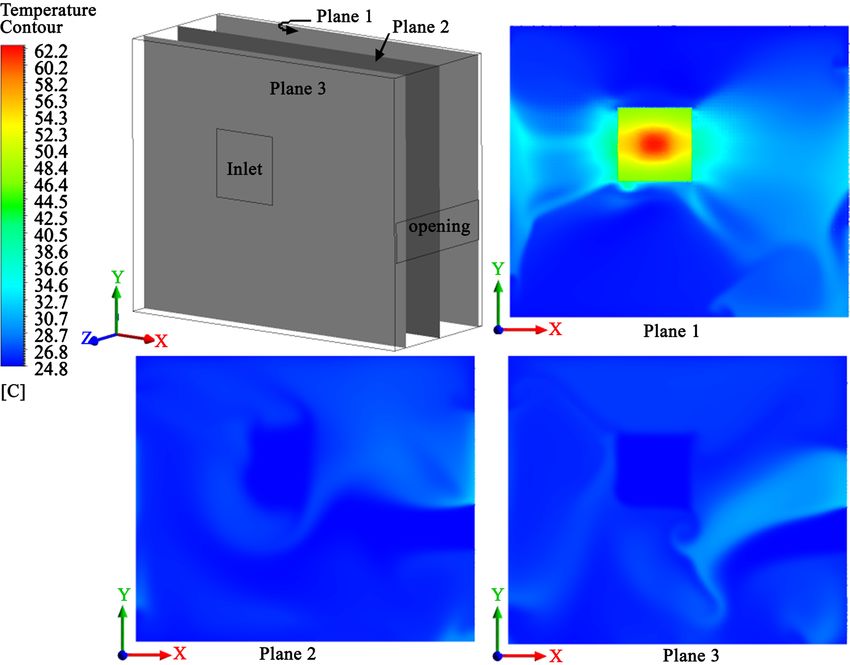
M. Z. I. Bangalee et al.

                                strategy, mesh density at heat sink, inlet, outlet and opening is made denser than
                                the rest of the computational domain. Primarily an unstructured tetrahedral
                                mixed mesh is generated for global parameter of maximum element of 6.0 mm
                                and density region of maximum element of 2.5 mm. This combination gives the
                                total of 3.1 million mesh elements. But to get a well converged and acceptable
                                solution an optimum mesh topology is required. For that reason, several meshes
                                are generated considering different global mesh parameters and density regions.
                                From the simulated results it is found that 5.5 mm global mesh parameter and
                                2.29 mm density region gives 4.0 million mesh elements which are chosen as op-
                                timum. This optimum mesh topology is shown in Figure 2 and Figure 3.

                                4. Validation of Methodology
                                To validate the results, a pin fin heat sink is considered which is reported by
                                Ozturk and Tari [22]. The heat sink is drawn according to the reported geometry
                                and the simulation is done considering the same boundary conditions.
                                   From Table 1, it is seen that the average temperature rises above ambient is
                                reported 18.7˚ where this temperature is found 20.9˚ in our computations. The
                                discrepancy in the temperature rise is 2.2˚ due to lack of analogy in the geometry,

                                Figure 2. Final meshed geometry.

                                Figure 3. Comparison view between global mesh region and density mesh region.

DOI: 10.4236/ojmsi.2020.91003                         48                     Open Journal of Modelling and Simulation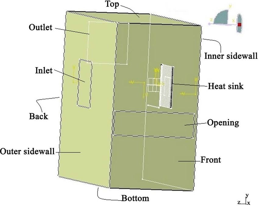
M. Z. I. Bangalee et al.

                                Table 1. Comparison of the temperature difference with [22] for 70 W heat source
                                (CPU).

                                                                                                    Alpha PAL8952        Present Case

                                                       Tmax ( K )                                         328                324.5

                                                       Tmin ( K )                                         316                315.9

                                                    Tmax − Tmin ( K )                                     12                  8.6

                                         Average rise above ambient, ∆T ( K )                             18.7               20.9

                                      Normalized non uniformity         (T
                                                                         max
                                                                               − Tmin ) ∆T                0.64               0.41

                                flow conditions and boundaries between two cases. The temperature difference
                                between Tmax is 3.5˚. The air velocity is not strong enough is the direct path
                                along the fan hub and the heat sink. As a result, a hot spot is induced on the heat
                                sink in that path. The larger maximum temperature in the heat sink [22] may be
                                attributed to this fact. In this present simulation for validation, no fan is consi-
                                dered, that creates no hot spot. That’s why our maximum temperature is rea-
                                sonably lower than that of the reported results [22].

                                5. Results and Discussion
                                A steady-state conjugate heat transfer process is studied here numerically. Flow
                                distribution and the effects of different boundary conditions are discussed here
                                as follows:

                                5.1. Effects of Outlet Position
                                Position of outlet is very important for flow distribution inside the chassis [19].
                                In the present work, the outlet is located on the back sidewall of the chassis as
                                mentioned previously. Eight different 3-D geometries are created for different
                                positions of the outlet. Table 2 represents the exact positions of the outlet on the
                                back sidewall with their orders. And the positions can be realized from Figure 4.
                                   With an optimum mesh topology for every case, simulations are done and all
                                results are gathered to find out the best position of the outlet. Results are shown
                                in tabular form in Table 3 as well as plotted graphically in Figure 5.
                                   From Figure 5 it is realized that the position 2, 3 and 5 give better perfor-
                                mance than the other positions. Comparing the position 2 and 3 it can be con-
                                cluded that to get better thermal performance, the position of outlet need to take
                                as corner as possible. This is because of the inlet air flow. For other positions of
                                outlet, inlet air flow is disrupted by the outlet. Air flow moves toward the outlet
                                without reaching the fin channel properly. There for convection rate is low for
                                these positions. Although position 2 is little bit better than 3 but in real case, to
                                set up outlet in that position can make difficulties, because, it has nuts, bolts or
                                screws. For that reason, further improvement of the present work position 3 is
                                chosen. But one should use the outlet as corner as possible in the similar case to
                                get better performance.

DOI: 10.4236/ojmsi.2020.91003                          49                                    Open Journal of Modelling and Simulation
M. Z. I. Bangalee et al.
Table 2. Positions of outlet in details with their orders.
Order of Order of
Exact position Exact position
position position
1 Middle of the wall 5 Along heat sink
2 10 mm from top and 5 mm from inner sidewall 6 Bottom half of the heat sink
3 (Chosen) 20 mm from top and 5 mm from inner sidewall 7 Top half of heat sink
20 mm from bottom and
4 20 mm from top and 80 mm from inner sidewall 8
middle of the wall
Figure 4. Different positions of outlet on the back sidewall of CPU chassis.
Table 3. Maximum CPU surface temperature for different positions of outlet.
Order of outlet position Temperature (˚C) Order of outlet position Temperature (˚C)
1 77.45 5 59.33
2 59.38 6 62.39
3 59.64 7 60.38
4 62.10 8 64.53
Figure 5. Maximum CPU surface temperature for different positions of outlet.
DOI: 10.4236/ojmsi.2020.91003 50 Open Journal of Modelling and SimulationM. Z. I. Bangalee et al.
5.2. Effects of Dimension of Inlet and Outlet
In the present work both inlet and outlet have the same dimension for the entire
work and that is 95 mm × 95 mm square. The larger the inlet/outlet the larger
the mass flow rate and therefore larger convective heat transfer rate. But CPU
chassis has complexity in real case. It has many wires and ports to connect peri-
pheral devices. Also, chassis contains other components such as power supply,
hard disk, motherboard, DVD drive etc. As a result, inlet and outlet can’t be so
large. Considering this phenomena five different dimensions of the inlet/outlet
are created and simulated to predict the desired dimension. For all cases in-
let/outlet is a square shaped and their position is 5 mm from inner sidewall and
20 mm from the top. The work history and simulated results are shown in Table
4 and Figure 6.
From Table 4 it is seen that in all cases, temperature varies from 59.31˚C to
60.38˚C that is acceptable. But 85 mm × 85 mm outlet is better than any other
dimensions. In the case of larger dimension air flow moves toward the surface
parallel to the outlet without reaching to the fin channel. And for smaller di-
mension, mass flow rate is lower. In the present case, 85 mm × 85 mm dimen-
sion of the inlet/outlet is comparatively suitable.
5.3. Effects of Inlet-Outlet Velocity Ratio
The inlet blows air inside the chassis and outlet blows air outside of the chassis.
Thus the velocity ratio of inlet and outlet is very important for flow distribution
inside the chassis, mostly around the heat sink and inside the fin channel of the
heat sink. To optimize the velocity ratio, several simulations are done for the ra-
tio of inlet-outlet from 1:1 to 1:2. In all cases, inlet has a fixed velocity (5 ms−1)
Table 4. Maximum CPU surface temperature for different dimensions of inlet-outlet.
Dimension of Dimension of
Temperature (˚C) Temperature (˚C)
inlet-outlet (mm) inlet-outlet (mm)
65 × 65 60.98 95 × 95 59.64
75 × 75 59.90 105 × 105 59.37
85 × 85 59.31
Figure 6. Maximum CPU surface temperature for inlet/outlet dimensions.
DOI: 10.4236/ojmsi.2020.91003 51 Open Journal of Modelling and SimulationM. Z. I. Bangalee et al.
but outlet velocity is varied from 5 ms−1 to 10 ms−1 in the interval of 2 ms−1. It is
found that 1:1.6 ratio helped the heat sink for giving higher convective heat
transfer rate. The work history and simulated results are summarized in Table 5
and Figure 7. It is observed from Figure 7 that for ratios 1:1.8 and 1:2, the
maximum temperature of CPU surface is greater than the other ratios. In these
cases, the outlet velocities are 9 ms−1 and 10 ms−1. For the larger outlet velocity,
inlet air flow is disrupted by the outlet. The flow moves toward the outlet with-
out reaching fin channel.
5.4. The Flow and Heat Transfer Characteristics
Numerical computations are carried out for a 91 W CPU (maximum load).
Having all of the analysis together, a general case is set for this study. In this
general case it is found that the horizontal fin orientation with 1:1.6 inlet-outlet
velocity ratio the heat sink gives a better thermal performance when outlet is lo-
cated at the top corner of the chassis, near to the inner sidewall. It is found that
the avergae temperature of the fluid inside the chassis is calculated 26.7˚C, that
is slightly above the room temperature. To visualize the flow field and heat
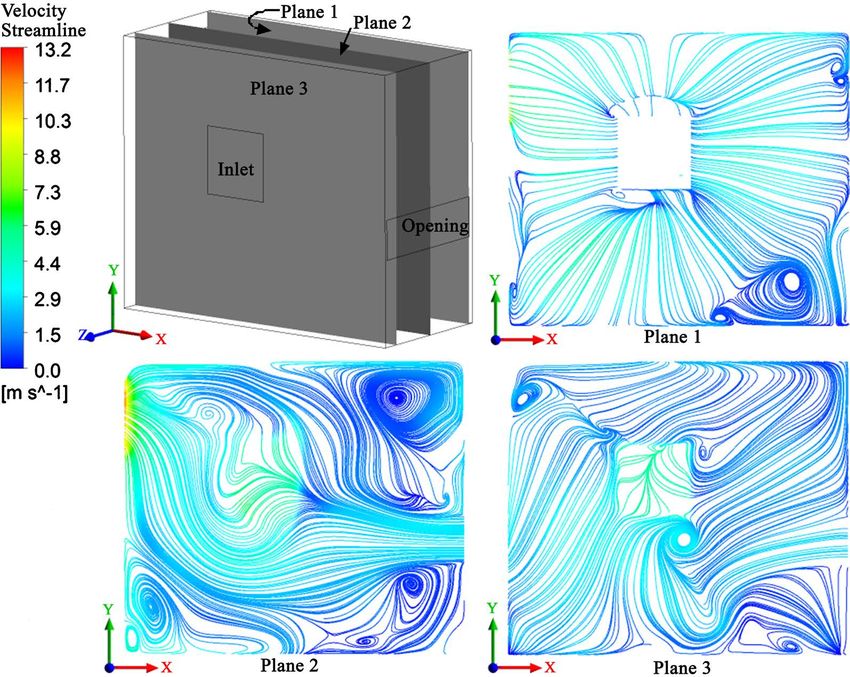
transfer characteristics inside the chassis, three planes are created, parallel to the
xy plane, namely plane 1, plane 2 and plane 3 ilustrated in Figure 8. Plane 1
passes through the contact region of the fin and the base plate of the heat sink,
plane 2 is located at the center of the chassis and plane 3 is located near to the
Table 5. Maximum CPU surface temperature for inlet-outlet velocity ratio.
Velocity (ms−1)
Velocity ratio of inlet-outlet Temperature (˚C)
Inlet Outlet
5 5 1:1 63.84
5 6 1:1.2 64.88
5 7 1:1.4 61.50
5 8 1:1.6 59.64
5 9 1:1.8 72.40
5 10 1:2 78.36
Figure 7. Maximum CPU surface temperature for velocity ratio of inlet and outlet.
DOI: 10.4236/ojmsi.2020.91003 52 Open Journal of Modelling and SimulationM. Z. I. Bangalee et al.
inlet. It is noted that the average temperature of plane 1, plane 2 and plane 3 are
34.43˚C, 26.15˚C and 26.45˚C, respectively. The overall temperature on plane 1
is relatively higher because, it passes through the heat sink.
The air flow path inside the chassis is very complicated. Air flow is entered
into the chassis through the inlet and opening, but left through the outlet. Air
flow path from the inlet and the outlet are shown in Figure 9 separately. Three
Figure 8. Temperature distribution inside the chassis.
Figure 9. Streamline from inlet (left) and from opening (right).
DOI: 10.4236/ojmsi.2020.91003 53 Open Journal of Modelling and SimulationM. Z. I. Bangalee et al.
different planes as mentioned peviously also represent the streamline pattern for
different positions shown in Figure 10. Inlet flow velocity is 5 m−1 and Reynolds
Number is 4.2 × 10³ that indicates that the flow is turbulent inside the chassis.
The flow path on the plane 1 passing through the heat sink is less turbulent than
that on other two planes and flow path on the plane 2 passing through the mid-
dle of the chassis is fully turbulent. Figure 9 and Figure 10 also show that how
flow is entered into the chassis and left through the outlet.
The velocity vector expresses the direction of velocity over the domain. And
the magnitude of the velocity can be realized from the scale. Higher and lower
velocities for different positions of the chassis are observed from Figure 11.
Higher velocity is found at the outlet, around fin or fin channel, inlet and open-
ing. It is noted that the average velocity on plane 1, plane 2 and plane 3 are 2.63
ms−1, 2.36 ms−1 and 1.91 ms−1, respectively.
6. Conclusions
A CPU Chassis is designed by the software CATIA containing a heat sink with
horizontal fin orientation and then the domain is discretized using ICEM CFD.
A two-equation based turbulence model is applied to capture the turbulence of
the flow field. The governing equation at each grid is solved to determine a more
effective geometry. The optimum velocity ratio of inlet/outlet, dimension of in-
let/outlet and positions of outlet are predicted. The following conclusions can be
Figure 10. Streamline pattern inside the chassis.
DOI: 10.4236/ojmsi.2020.91003 54 Open Journal of Modelling and SimulationM. Z. I. Bangalee et al.
Figure 11. Velocity vector inside the chassis.
drawn from the results.
• The Reynolds number based on inflow velocity and geometry is 4.2 × 10³,
which indicated turbulent flow. The turbulent nuture of the flow is visible in-
side chassis.
• The studied model is found feasible to cool down the CPU.
• Heat sink has better thermal performance when outlet is positioned in the
top corner of the chassis, near to the inner sidewall.
• A larger size of inlet/outlet is responsible for a higher mass flow rate, but in
the present case, no significant change in maximum temperature is found for
four-square shaped inlet/outlet from 95 mm × 95 mm, to 65 mm × 65 mm in
the interval of 10 mm. Temperature variation of them is found 1.07˚C. Rela-
tively better performance is gained from the dimension 85 mm × 85 mm.
• The proper thermal performance is achieved for inlet-outlet velocity ratio of
1:1.6.
For time limitation, this study considered the steady case only. However, an
unsteady simulation is obviously a better choice to capture the real time pheno-
mena. As unsteady simulation needs more computational time and more ad-
vanced computational facilities, this paper only examines steady-state cases. How-
ever, for more accurate results unsteady computations are necessary. A study on
this topic may be extended considering the unsteadiness of the phenomena.
DOI: 10.4236/ojmsi.2020.91003 55 Open Journal of Modelling and SimulationM. Z. I. Bangalee et al.
Conflicts of Interest
The authors declare no conflicts of interest regarding the publication of this
paper.
References
[1] Carr, J.D. (2014) An Examination of CPU Cooling Technologies.
http://www.dsiventures.com
[2] Magadum, P.P. and Shamrao, G.M. (2015) Analysis & Optimization of Processor
Cooling Fins. International Journal of Engineering and Innovative Technology, 5,
90-94.
[3] Processor Core i7 7700k.
http://ark.intel.com/products/97129/Intel-Core-i7-7700K-Processor-8M-C
[4] Tuckerman, D.B. and Pease, R.F.W. (1981) High Performance Heat Sinking for
VLSI. IEEE Electron Device Letters, 2, 126-129.
https://doi.org/10.1109/EDL.1981.25367
[5] Pastukhon, V.G. and Maydanik, Y.F. (2006) Low-Noise Cooling System for PC on
the Base of Loop Heat Pipes. Institute of Thermal Physics, Ural Branch of the Rus-
sian Academy of Science, Ekaterinburg.
[6] Moon, S.H., Hwang, G., Yun, H.G., Choy, T.G. and Kang, Y. (2002) Improving
Thermal Performance for Notebook PC Cooling. Microelectronic Reliability, 42,
135-140. https://doi.org/10.1016/S0026-2714(01)00226-8
[7] Kim, K.-S., Won, M.-H., Kim, J.-W. and Back, B.-J. (2003) Heat Pipe Cooling
Technology for Desktop PC CPU. Applied Thermal Engineering, 23, 1137-1144.
https://doi.org/10.1016/S1359-4311(03)00044-9
[8] Choi, J., Jeong, M., Yoo, J. and Seo, M. (2012) A New CPU Cooler Design Based on
an Active Cooling Heat Sink Combined with Heat Pipes. Applied Thermal Engi-
neering, 44, 50-56. https://doi.org/10.1016/j.applthermaleng.2012.03.027
[9] Satio, Y., Nguyen, T., et al. (2005) Revolution in Fan Heat Sink Cooling Technology
to Extended and Maximize Air Cooling for Performance Processor in Lap-
top/Desktop/Several Application. IPACK 2005-7386, San Francisco, 17-22 July
2005, 431-437.
[10] Stafford, J., Walsh, E., Egan, V. and Grimes, R. (2010) Flat Plate Heat Transfer with
Axial Fan Flows. International Journal of Heat and Mass Transfer, 53, 5829-5638.
https://doi.org/10.1016/j.ijheatmasstransfer.2010.08.020
[11] Li, J. (2011) Computer Aided Modeling and Simulation of Cooling Fan. Interna-
tional Symposium on Information Engineering and Electronic Commerce (IEEC
2011), Bridgeport (USA), January 2011.
[12] Mousavi, H., Darazi, A.A., Farhadi, M. and Omidi, M. (2018) A Novel Heat Sink
Design with Interrupted, Staggered and Capped Fins. International Journal of
Thermal Science, 127, 312-320. https://doi.org/10.1016/j.ijthermalsci.2018.02.003
[13] Zeng, S., Kanargi, B. and Lee, P.S. (2018) Experimental and Numerical Investigation
of a Mini Channel Forced Air Heat Sink Design by Topology Optimization. Inter-
national Journal of Heat and Mass Transfer, 121, 663-679.
https://doi.org/10.1016/j.ijheatmasstransfer.2018.01.039
[14] Koplow, J.P. (2010) A Fundamentally New Approaches to Air-Cooled Heat Ex-
changers. Sandia National Laboratories. https://doi.org/10.2172/984140
[15] Staats, W.L. and Barisson, J.G. (2015) Active Heat Transfer Enhancement in Air
DOI: 10.4236/ojmsi.2020.91003 56 Open Journal of Modelling and SimulationM. Z. I. Bangalee et al.
Cooled Heat Sink Using Integrated Centrifugal Fans. International Journal of Heat
and Mass Transfer, 82, 189-205.
https://doi.org/10.1016/j.ijheatmasstransfer.2014.10.075
[16] Dang, C., Jia, L. and Lu, Q.Y. (2016) Investigation on Thermal Design of a Rack
with the Pulsating Heat Pipe for Cooling CPUs. Applied Thermal Engineering, 110,
390-398. https://doi.org/10.1016/j.applthermaleng.2016.08.187
[17] Wang, Y.B., Zhu, K., Cui, Z. and Wei, J. (2019) Effects of Location of the Inlet and
Outlet on Heat Transfer Performance in Pin Fin CPU Heat Sink. Applied Thermal
Engineering, 151, 506-513.
[18] Prajapati, Y.K. (2019) Influence of Fin Height on Heat Transfer and Fluid Flow
Characteristics of Rectangular Micro Channel Heat Sink. International Journal of
Heat and Mass Transfer, 137, 1041-1052.
https://doi.org/10.1016/j.ijheatmasstransfer.2019.04.012
[19] Zhong, Y.K., Hu, L., Chen, D.Q., Liu, H.D., Yuan, D.W. and Liu, W.X. (2019) CFD
Simulation on the Flow and Heat Transfer Characteristics of Mist Flow in
Wire-Wrapped Rod Bundle. Nuclear Engineering and Design, 345, 62-73.
https://doi.org/10.1016/j.nucengdes.2019.02.003
[20] ANSYS CFX. http://www.ansys.com/Products/Fluids/ANSYS-CFX
[21] CATIA. http://www.3ds.com/products-services/catia
[22] Ozturk, E. and Tari, I. (2008) Forced Air Cooling of CPUs with Heat Sink: A Nu-
merical Study. IEEE Transaction on Components and Packaging Technologies, 31,
650-660. https://doi.org/10.1109/TCAPT.2008.2001840
DOI: 10.4236/ojmsi.2020.91003 57 Open Journal of Modelling and SimulationM. Z. I. Bangalee et al.
Nomenclature
K Thermal conductivity [wm−1∙k−1]
A Cross sectional area [cm2]
As Surface area [cm2]
T Temperature [˚C]
Ts Surface temperature [˚C]
T0 Ambient fluid temperature [˚C]
g Gravitational acceleration [ms−2]
h Convective heat transfer coefficient [wm−2∙k−1]
Cp Specific heat capacity [Jkg−1∙k−1]
k Turbulence kinetic energy per unit mass [m2∙s−1]
ε Dissipation rate
F1, F2 Blending function
u, v, w x, y and z components of velocity respectively [ms−1]
x, y, z Cartesian coordinate [m]
p Pressure [kg∙m−1∙s−2]
Q Rate of conduction
r′ Vector from upwind node to the point
Greek Symbols
β Thermal expansion coefficient [k−1]
µ Dynamic viscosity [kg∙m−1∙s−1]
µt Turbulence viscosity [kg∙m−1∙s−1]
ν Kinematic viscosity [m2∙s−1]
ρ Density of the fluid [kg∙m−3]
σT Thermal diffusivity
ϕ Flow property at the node
ω Turbulence frequency [s−1]
DOI: 10.4236/ojmsi.2020.91003 58 Open Journal of Modelling and SimulationYou can also read