Flow Challenges - Flow eHandbook
←
→
Page content transcription
If your browser does not render page correctly, please read the page content below

Flow eHandbook

How to Fight
Flow Challenges
                  Start u
Table          of       Contents
Carefully Commission Hydrogen Pipe                                                                                   3
Safety depends upon scrupulously performing a variety of inspections and tests

Get Up to Speed on Axial Compressors                                                                                 6
These complex machines provide benefits but also pose concerns

Fight Flow Recirculation                                                                                             9
But first understand why the phenomenon occurs in centrifugal pumps

Ad Index
Porter                                                                                                               5
www.porterinstrument.com
Burkert                                                                                                            11
us.burkert.com

Flowmeter Suits Low-Flow Applications
Device uses surface acoustic wave technology to measure volume flow, temperature and density

The FLOWave flowmeter uses surface acoustic waves (SAW) technology, which relies
on the propagation of waves for measurements, similar to those in seismic activities.
    FLOWave indicates its device status based on Namur NE107 definitions, and
requires minimal maintenance. Both shorten downtime, resulting in lifecycle cost reduc-
tions. Transmitter, sensor and measuring tube stand up to strict hygienic requirements.
    In addition to volume flow, temperature and density can be measured, too. Based on
this data, the mass flow rate can be calculated. The flowmeter also works with stagnant
liquids so results are available even with the smallest flow volumes. It recognizes quick
flow rate changes reliably, thus making it suitable for very fast filling processes. The
high excitation frequency of 1.5 MHz avoids disturbances due to inherent vibration in
the plant. Magnetic and electrical effects have no influence on measurements. It’s reliable even in the presence of gas
bubbles or solid particles, and can distinguish between laminar and turbulent flows, says the company.

us.burkert.com

t Previous page                                               2                                                   Next Page u
Carefully Commission Hydrogen Pipe
Safety depends upon scrupulously performing a variety of inspections and tests

By Dirk Willard, Contributing Editor

A low-pressure alarm sounded on a refinery hy-                       correcting component issues, weld the piping; follow with
drotreater-compressor suction line during startup. Two op-           commercial-grade cleaning. Assemble the spools completely:
erators were dispatched. Minutes later, hydrogen collecting          do bench assembly tests. Pay attention to weight — badly
under the roof of the poorly ventilated compressor building          balanced, heavy spools are difficult to assemble, so add lift-
exploded, killing them. Investigators later determined the           ing lugs as needed. Redesign poorly placed vents and drains
cause to be a leaky, poorly sized gasket that passed inspec-         to ensure proper slope. Polish smooth all rough welds and
tion during construction.                                            perform surface treatment to reduce thermal expansion and
    This accident highlights the need for greater care in            cold working. If pigs will be used in cleaning, confirm a
commissioning hydrogen systems. Unfortunately, advice is             clear path and the means of pigging. Take special precau-
sparse. Background yourself on such systems by reviewing:            tions with relief vents: sharp angles and a sudden discharge
ASME STP-PT-006, “Design Guidelines for Hydrogen Pip-                promote mixing that can lead to spontaneous H2 fires.
ing and Pipelines;” NACE Standard TM 0284-2003, “Evalu-              Inspection failures take you back to square one.
ation of Pipeline and Pressure Vessel Steels for Resistance to           Effective cleaning of the spools eliminates future
Hydrogen-Induced Cracking;” and API-RP 941, “Steels for              field-assembly problems. Some components will require
Hydrogen Service at Elevated Temperatures and Pressures in           disassembly and separate cleaning and drying. Pigs usually
Petroleum Refineries and Petrochemical Plants.”                      are used for pipe: first, soft shell pigs to look for obstruc-
    Begin the commissioning process by focusing on the               tions; then rubber shell pigs for moving cleaning agents and
spools. Examine every component before assembly. Require             dewatering; and finally wire brush pigs to remove pipe scale
vendors to provide complete records on materials and test-           from carbon steel (CS), followed by a descaler chaser. Wire
ing data for gaskets and pipe. Welds and parent metal both           brush pigs generally aren’t used with stainless steel (SS)
should have a maximum Rockwell hardness of 22 and a                  pipe. If you intend to send a wire brush pig through SS pipe,
Brinell hardness of 250. Don’t treat instruments as whole            confirm the pig previously hasn’t been used for CS. Do a
devices: inspect the parts. After reviewing the data files and       ferroxyl test of SS to detect rust contamination. Cleaning

t Previous page                                                  3                                                     Next Page u
generally involves a slug of detergent or mild caustic, fol-         with a secondary fuel for the flare once the H 2 is depleted.
lowed by water and a citric acid solution to passivate the SS,           Field assembly is next. Record the flange torques after
and finally buffered water and dewatering. Muriatic acid is a        inspecting the final gaskets; tighten again during initial
descaler often used for CS after detergent. Verify that gasket       operation. Fires have resulted from leaks caused by poor
materials are compatible with cleaning solvents.                     monitoring of flange torques during hot-bolting, especially
     Drying is next, usually with nitrogen or air, although          where SS bolts are used with CS flanges (because SS under-
argon has been used because it sweeps slightly better than           goes greater thermal expansion). Take care to ensure that
nitrogen. Dry by intermittent purging until the difference           instruments are included. A standard pressure test is next
between input and output dew points is
Together, we can simplify your challenges with
 turnkey flow and pressure assemblies.
 With years of experience in custom OEM solutions and Parker's vast resources at our disposal,
 we can design and build the perfect custom flow/pressure device, saving you time and money.
 That’s the Porter Promise.
       • A comprehensive range of flow and pressure technologies
       • Knowledgeable application engineering support
       • Reliable after-sale customer service
       • Dependable just-in-time delivery
 To ensure peace of mind and process reliability, visit us today at PorterInstrument.com.

t Previous page                                 5                                       Next Page u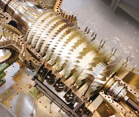
Get Up to Speed on Axial Compressors
These complex machines provide benefits but also pose concerns

By Amin Almasi, rotating equipment consultant

An axial compressor is a compact turbo-compressor                                        AXIAL COMPRESSOR

that suits applications with a very large flow and a
relatively small pressure difference (head). It probably is
one of the most crucial and complex turbo-machines at
many process plants. Achieving and maintaining desired
performance depends upon properly addressing some
complicated design and operational issues. These include
fragile blades, manufacturing problems, surge, stall,
noise-related concerns and many more.
    An axial compressor (Figure 1) offers higher effi-
ciency, speed capability and capacity for a given size than
a centrifugal compressor. However, it has a narrower
recommended application range (Figure 2) and delicate
components. Some compressors contain both axial and
centrifugal stages (Figure 3).
    Some operating companies will use whenever possible
rugged, versatile and reliable centrifugal compressors                 Figure 1. Units such as this can handle large flows with relatively small
instead of dedicated, efficient but fragile axial machines.            head. Source: Siemens.

Large horizontally split centrifugal compressors now are
available in capacities up to ≈450,000 m 3/h or even more.                                  APPROXIMATE APPLICATION REGIONS
However, for very large capacities (say, >1,000,000 m 3/h),                                          10 4
an axial compressor may be the only option.
    It’s difficult to give a general rule for selecting be-
                                                                          Discharge Pressure, Barg

                                                                                                     10 3
tween a very large, sturdy centrifugal compressor and                                                                       CENT RIFUGAL
a compact, relatively more efficient, properly optimized
more-economical axial machine.                                                                       10 2

DESIGN ISSUES
                                                                                                     10 1
Many chemical plants require axial compressors to operate
within a relatively wide operating envelope (capacity/pressure                                                                                     AXIAL
range), and sometimes relatively far from nominal condi-                                             10 0
tions. Considering the steep nature of an axial compressor’s
curve, this is a great challenge. Variable-speed and the vari-
able inlet-guide-vanes (IGV) systems can provide additional                                                 10 1   10 2     10 3     10 4       10 5        10 6
flexibility in operation. A number of issues, including struc-                                                            Inlet Flow, m 3 / h
tural, vibration, weight, cost, manufacturability, accessibility       Figure 2. Axial compressors have a narrower operating range than
and reliability, need evaluation for any axial compressor.             centrifugal machines.

t Previous page                                                    6                                                                                   Next Page u
DIFFERENT TYPES OF STAGES

     The operating Mach number usually is less than 0.8 for
a subsonic cascade but can go up to 2 or more at the tip of
a transonic blade assembly. Some subsonic axial stages can
develop pressure ratios on the order of 1.5–1.8. The transonic
stages operate with pressure ratios of ≈2 and greater while
maintaining an acceptable efficiency and aerodynamic design.
A well-designed subsonic axial stage can achieve a polytropic
efficiency of ≈0.9. The polytropic efficiency for transonic
blades is a bit lower, say, ≈0.82–0.89. High peripheral-mean-
stage rotor velocities can reach ≈300–340 m/s for subsonic ro-
tors and up to ≈580 m/s for transonic ones. Designers set the
annulus radius (or hub-to-tip) ratio, R hub/Rtip, after a careful
                                                                        Figure 3. The initial (high flow) stages of this compressor are axial while
optimization that considers aerodynamic, technical, mechani-            the final two stages (low flow) are centrifugal. Source: Siemens.
cal and economic constraints. For inlet stages, assigned R hub/
Rtip values usually range between 0.45 and 0.65 while outletpattern; variation shouldn’t exceed a specified level.
stages often get a higher value, typically from 0.75 to 0.9, to  The ultimate goal of an axial compressor design is to cre-
achieve a relatively high Mach number.                      ate an axial blade arrangement with the maximum pressure
     A proper axial compressor design should avoid a flow   rise and the minimum total pressure loss, i.e., a relatively high
separation inside the machine. Analysis of axial Mach       efficiency, along with an acceptable operating range.
number distribution along the different blade stages is          The different blade and component profiles play an
essential. This distribution should follow an acceptable    important role because these can affect the nature of the
                                                                                       boundary layers and, therefore, the
                                                                                       amount of losses (and the operating
  RELATED CONTENT ON CHEMICALPROCESSING.COM                                            margins). The stage arrangement is
    “Carefully Consider Nozzle Loads,” http://goo.gl/3w93Y9                            critical; the stage stacking procedure
    “How Much Will Your Compressor Installation Cost?,” http://goo.gl/qM0jOS           intrinsically is iterative.
    “Apply Wet Screw Compressors Wisely,” http://goo.gl/ER8i8y                              Maximizing the adiabatic ef-
    “Choose the Right Air Compressor,” http://goo.gl/kKeQ6g                            ficiency can significantly impact
    “Make the Most of Reciprocating Compressors,” http://goo.gl/QBnMAl                 the choice of stage geometrical and
    “Correctly Commission Rotating Equipment,” http://goo.gl/3G9qDm                    functional variables. In addition,
    “Rethink Options for Large Drivers,” http://goo.gl/QhmFJR                          it’s important to optimize the
    “Avoid Bad Turns with Rotating Equipment,” http://goo.gl/VhMVYY                    surge/stall margins.

t Previous page                                                     7                                                                Next Page u
An optimum axial compressor design combines mini-               be opened to provide sufficient flow to the compressor
mum weight with compactness. This calls for decreasing              suction to avoid surge at initial stage(s).
the number of stages and increasing individual stage load-               Dynamic simulation is crucial. The model requires ac-
ing, which can affect the choice of blade shape and cascade         curate, actual dynamic performance data such as the IGV
parameters.                                                         stroke speed, the control and actuator delay, and the valve
    The availability of advanced materials for blade/com-           stroke time. These data play important roles in dynamic
ponent construction and high-quality production methods             simulation results, anti-surge system design, reliability and
makes it possible to reach levels of aerodynamic loading            overall safety. Proper validation of the model is essential,
never before possible in axial compressors while preserving         considering the criticality of avoiding surge and the disas-
high levels of efficiency for normal and alternative opera-         trous consequences of a surge event.
tion cases. This is true both for high-speed subsonic as well           The IGV stroke time usually is in the range of 2–6 s.
as ultra-high-speed transonic blades.                               Conceptually, fast response of the IGV system might seem
                                                                    desirable as it could help unload the compressor quickly.
SURGE CONTROL                                                       However, the IGV stroke could affect the performance
A surge event can damage or even separate the fragile               curve — for example, the distance between the operating
blades of an axial compressor. However, the machine’s               point and surge. Results from some dynamic simulations
surge line maps are complex. The surge line could change            indicate that fast closing of the IGV mechanism some-
with a slightly different gas condition or composition. So,         times (depending upon the compressor’s operating map)
an axial compressor requires a dedicated anti-surge system.         could drive the machine toward surge. This suggests that
This usually includes five protection arrangements:                 a moderate IGV stroke time, say, 3–5 s, rather than the
    • an anti-surge valve;                                          fastest time, might be better for surge prevention. The
    • a hot-gas-bypass valve;                                       stroke time of an IBV possibly could be as short as 1.5–2
    • an inter-stage bleed valve (IBV);                             s. However, for a machine in which surge could initiate
    • an IGV system; and                                            at the final stages, fast IBV opening could pose problems
    • speed variation.                                              because it can significantly reduce the gas flow at the final
    The speed reduction and IGV characterization should             stages. So, it’s important to determine an optimum win-
be used to map the “surge area” in a two-dimensional                dow for the opening time to avoid surge in either section
plot. In addition to an anti-surge valve, an axial compres-         of axial stages. Accurate dynamic simulations are essential
sor most often is protected by a hot-gas-bypass (HGBP)              for identifying all these optimum values.
recycle loop, usually with a hot-gas-bypass valve. This is
mandatory if the anti-surge valve isn’t installed immedi-           AMIN ALMASI is a rotating equipment consultant based in Brisbane,
ately after the compressor discharge. The IBV also should           Australia. E-mail him at amin.almasi@ymail.com.

t Previous page                                                 8                                                         Next Page u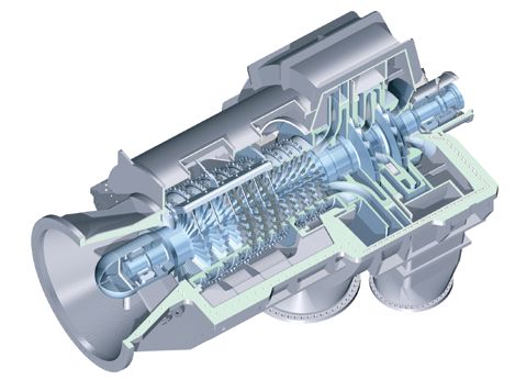
Fight Flow Recirculation
But first understand why the phenomenon occurs in centrifugal pumps

By Andrew Sloley, Contributing Editor

Suction recirculation can undermine operation                           END-ON VIEW OF IMPELLER

of a centrifugal pump at low flows. The pump’s suction
specific speed and suction energy can provide insights
about potential difficulties (see: “Cut Pump Speed to Cut
Problems,” http://goo.gl/smNPqX). Variable frequency
drives (VFDs) frequently can provide a solution (“Consid-
er VFDs for Centrifugal Pumps,” http://goo.gl/cXFbPk).
    Fixing suction recirculation problems often costs
money. Typically, getting the funding requires convincing
the holder of the purse strings of what’s the real cause of a
problem.
    Many people have trouble grasping the idea that flow
can go backward within a centrifugal pump. Over the years,
I’ve often struggled to find a fundamentally correct but
simple explanation.
                                                                                          Incidence Angle
    First, we must realize that what’s simple to a mechanical
engineer may appear complicated to a chemical engineer.            Figure 1. The incidence angle at which inlet flow contacts the impeller’s
So, let’s explain the phenomenon in ways both groups can           leading edge affects eddy flow formation.

understand.
    For mechanical engineers, a centrifugal pump increases         formation. As flow rates drop, the eddies formed become
the pressure of a liquid stream. The natural direction of          larger. Eventually, eddies
                                                                                   Average  flowcan    create partial flow from the
                                                                                                 velocity
fluid flow is from high pressure to low pressure. Fluid flow       pump dischargevector
                                                                                     to the
                                                                                          at pump
                                                                                              1.0 × BEPsuction. The local flow pattern
through the pump occurs because the rotating impeller              follows the outlineExample
                                                                                        shownvane in Figure 1.
provides velocity to generate pressure. The velocity gradient          For chemical engineers,
                                                                                       exit velocityit’s better to consider how pump
                                                                                        vectors at
creates the discharge pressure.                                    flow patterns interact   with material balance boundaries. A
                                                                                        1.0 × BEP
    In a centrifugal pump, liquid enters the suction eye at        series of material balance boundaries through the pump
the center of the impeller disc. The liquid changes velocity       always will have the same net flow as the pump suction
before exiting the pump at the impeller periphery. To deal         flow. If pump suction flow drops, the net flow through any
with the geometry of flow from the center to the edge              cross section of the pump drops. Because typical fluids are
of the impeller and changes in velocity, the flow passage          incompressible at most conditions, this creates an absolute
shape changes. Figure 1 showsExample
                                  an end-oninlet view of an im-    requirement that average velocity in any cross section varies
peller that’s rotating counter-clockwise     and Figure 2 shows
                                velocity vectors                   linearly with flow rate.
                                 at 1.0 × BEP
a side view.                                                           However, close to the pressure edge (the leading
    Inlet flow contacts the impeller’s leading edge at a           surface) of the impeller, impeller speed sets liquid velocity.
specific incidence angle (Figure 1). Vector analysis of liquid     If average liquid velocity must drop but velocity in that
flow directions shows the incidence angle affects eddy             area of the flow passage is close to constant, velocity in

                                                         Average flow
t Previous page                                                  9
                                                       velocity vector at                                                      Next Page u
                                                          0.25 × BEP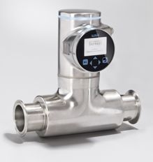
Incidence Angle

    IMPELLER SIDE VIEW

                                                    Average flow velocity
                                                     vector at 1.0 × BEP

                                                        Example vane
                                                         exit velocity
                                                          vectors at
                                                          1.0 × BEP
                                                                                pump are simply too big. Nevertheless, they must be
                                                                                filled with liquid. Flow recirculation results.
                                                                                     Flow recirculation can damage the impeller due to cav-
                                                                                itation caused by vaporization in the low-pressure regions
                                                                                that recirculation creates. Flow recirculation also stresses
    Example inlet                                                               pump components with unbalanced forces and vibration.
  velocity vectors                                                                   Both mechanical and process changes can reduce the
    at 1.0 × BEP
                                                                                consequences of flow recirculation.
                                                                                     Mechanical solutions focus on the pump. For instance,
                                                                                impeller-volute-geometry matching and vane-angle,
                                                                                leading-edge and inlet-eye modifications,
                                                                                as well as pump speed changes all can improve pump flex-
                                 Average flow                                   ibility. However, each affects efficiency, discharge head and
                               velocity vector at
                                  0.25 × BEP
                                                                                capacity differently.
                                                                                     One process modification adds a recirculation loop
                              Example vane exit                                 to keep the pump out of the low flow region. Recircula-
                              velocity vectors at
                                  0.25 × BEP                                    tion systems require extra equipment (piping, restriction
                                                                                orifices, control valves, etc.). In my experience, many flow
                                                                                control loops are abandoned due to maintenance costs or
                                                                                ignorance of their importance.
                                                                                     Another process modification provides excess suc-
                                                                                tion head to the pump. This helps prevent cavitation-like
                                                                                damage. Even the low-pressure regions in the pump have
    Example inlet                         Recirculation                         sufficient head to keep the fluid above its bubble point.
   velocity vectors
    at 0.25 × BEP                                                               However, extra suction head doesn’t solve stress and vibra-
                                                                                tion problems. At some point, pump vibration may exceed
                                                                                good practice values. Extra stress and vibration decrease
                                                                                mean time between repair and mean time between failure.
Figure 2. Proper flow takes place at the BEP (top) but at 0.25 BEP (bottom), to Maintenance costs rise with high vibration and stress.
satisfy the average velocity requirement, recirculation occurs.
                                                                                Reduced operating speed lowers vibration and pump loads.
                                                                                     While it may not be a perfect solution, switching to
           other areas must fall even more than the average. At some            a VFD    can benefit nearly every centrifugal pump service
           point, when average velocity decreases enough, the flow              suffering from inlet recirculation.
           direction in areas far from the impeller’s leading edge                   Picking the right option requires a thorough analysis of
           must reverse to meet the average velocity requirement.               both mechanical and process constraints and costs.
           Figure 2 shows a schematic of net flow in a pump at its
           best efficiency point (BEP) and at a low flow condition              andrew sloley, Contributing Editor
           (0.25 of the BEP). At low rates, the flow passages in the            ASloley@putman.net

        t Previous page                                                     10                                                  Next Page u
Visit us at WEFTEC
Booth #4705
“Who‘s to say that there
have to be sensor elements
in the measuring tube of a
flowmeter?”
Using the patented SAW technology
our new FLOWave flowmeters need no
sensor elements in the measuring tube.
Thus they provide reliable results even in
challenging hygienic applications.
www.inspiring-answers.com
t Previous page 11You can also read