CHILLER INSTALLATION GUIDE & USER MANUAL - SINGLE & DUAL STAGE CHILLERS
←
→
Page content transcription
If your browser does not render page correctly, please read the page content below

CHILLER INSTALLATION
                 GUIDE & USER MANUAL

                  - SINGLE & DUAL STAGE CHILLERS

1.800.555.0973    INFO@GDCHILLERS.COM   GDCHILLERS.COM/INSTALLATION-VIDEOS
I

    SINGLE & DUAL STAGE CHILLER MANUAL
          ©2021 G&D CHILLERS, INC.
            ALL RIGHTS RESERVED

                                         2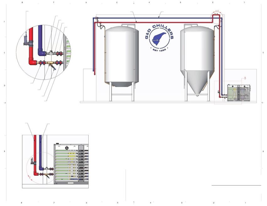
INSTALLATION GUIDE              • USER MANUAL                                                 SINGLE & DUAL STAGE MODELS

    CONTENTS
       CONTACT INFORMATION & AFTERHOURS SUPPORT ......................................................... 4

       INSTALLATION VIDEO LINKS ................................................................................................ 4

       PACKAGE CHILLER DESCRIPTION ........................................................................................ 5

       INSTALLATION REQUIREMENTS .......................................................................................... 6

       PIPING RECOMMENDATIONS ............................................................................................. 7

       CONTROLLER AND NAVIGATION ........................................................................................ 9

       C.PCO CAREL MINI ALARMS ............................................................................................. 10

       START-UP INSTRUCTIONS ................................................................................................. 11

       WARRANTY START-UP CHECKLIST ..................................................................................... 12

       SEQUENCE OF OPERATION ............................................................................................... 13

       MAINTENANCE .................................................................................................................. 13

       TROUBLESHOOTING...........................................................................................................14

       PROPYLENE GLYCOL CHART............................................................................................... 17

       WARRANTY STATEMENT ................................................................................................... 18

G&D CHILLERS, INC. • GD-MNL_SD_CM-R2021A
                                                                                                                                           3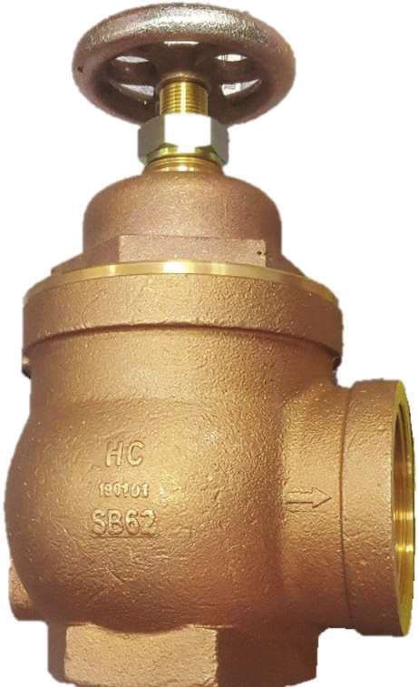
I

CONTACT INFORMATION & AFTERHOURS SUPPORT
CONTACT INFORMATION
G&D Chillers, Inc.
760 Bailey Hill Rd.
Eugene, Oregon 97402
1.800.555.0973
info@gdchillers.com
Office Hours: 8 AM – 5 PM PST

AFTERHOURS TECHNICAL SUPPORT
G&D Chillers offers 24/7 technical support. For emergency assistance after normal business hours, call the main office
at 1.800.555.0973. The voicemail recording will provide contact information for the emergency on-call service
technician.

INSTALLATION VIDEO LINKS
Visit the following pages for installation video walk-throughs and FAQs:

gdchillers.com/installation-videos/

gdchillers.com/installation-videos/how-to-install-a-chiller

gdchillers.com/faq

               NOTICE: CHILLER WARRANTY REQUIRES ACTIVATION
                  To activate the chiller parts and labor limited warranty, complete the
                  Warranty Start-Up Checklist and return to G&D Chillers within 30 days.

                                                                                                                   4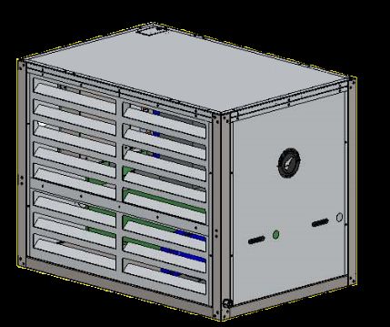
INSTALLATION GUIDE          •   USER MANUAL                           SINGLE & DUAL STAGE MODELS

PACKAGE CHILLER DESCRIPTION
CONDENSER                                                REFRIGERANT PIPING
AIR COOLED – Standard configuration. Copper tube         Type L ACR copper. Liquid line-filter drier, sight
aluminum fin condenser coil or micro-channel             glass/moisture indicator, solenoid valve and thermal
condenser coil. Direct drive propeller type fans with    expansion valve with equalizer. Suction line fully
DDP motors and built-in overload protection. Design      insulated and designed for proper oil return with
test pressure 150 PSIG low side, 300 high side.          minimum friction loss. Discharge line formed of ACR
                                                         tubing reformed radius fittings. All piping leak tested
LIQUID COOLED – Optional configuration. Brazed
                                                         and evacuated. Ships with full operating charge of
plate counterflow condenser with water regulation
                                                         refrigerant, refer to data plate for refrigerant type
valve. Shell and tube condensers available for custom
                                                         and charge per circuit.
units.
                                                         FRAME & HOUSING
EVAPORATOR
                                                         Fully powder coated steel frame. Durable powder
Brazed plate counterflow heat exchanger fed by
                                                         coated aluminum housing rated for outdoor use.
externally-equalized thermostatic expansion valve.
                                                         Louvered access panels for easy service and
                                                         maintenance.
COMPRESSOR
Hermetically-sealed Maneurop compressor with oil
                                                         POWER & CONTROLS
level sight glass, rotalock service valves, and
                                                         A single-point electrical connection is provided for
crankcase heater.
                                                         terminating the chiller power wiring. All power
                                                         starting controls and safety/operating controls are
CIRCULATION PUMP
                                                         mounted in a weatherproof steel NEMA 3R enclosure.
End suction centrifugal pump with impeller trimmed
for 35% propylene glycol mixture. Base mounted.          Features include:
Pump fitted with union, check valve, and supply and       • Programmable logic controller (PLC)
return shut off valves for service. Variable frequency    • On / pump down / off door switch
drives available upon request.                            • Compressor contactor and circuit breaker
                                                          • Pump contactor and circuit breaker
RESERVOIR TANK                                            • Pressure-based mechanical safeties
Constructed of molded, seamless high-density cross-       • Flow switch interlock
linked polyethylene or stainless steel. Insulated with    • Freeze protection interlock
½” closed cell foam. Glycol level indicator. Auxiliary    • High temperature alarm
ports standard on most units.                             • Low ambient control
                                                          • Compressor anti short cycle timer
SUPPLY & RETURN PIPING
                                                          • Fan cycling switches (air cooled units)
Constructed of type M copper. Ball valves provided
                                                          • Water regulating valve (water cooled units)
for field connection of supply and return piping.
Liquid-filled pressure gauge for setting discharge
                                                         FACTORY TESTING
pressure.
                                                         All chillers are run tested at the factory and verified
DYNAMIC FLUID BYPASS VALVE                               to be in perfect working order prior to shipment.
Allows for balancing of discharge pressure. Over
pressure design allows circuiting back to tank without
damage to system or pump. Copper and bronze
construction.

G&D CHILLERS, INC. • GD-MNL_SD_CM-R2021A
                                                                                                              5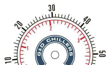
I

INSTALLATION REQUIREMENTS
LOCATION
Air cooled units must sit outside on a
solid level surface. A concrete pad is
recommended. Location should be free
of grass and other debris that could plug
condenser fins.

Ensure minimum clearance* between
condenser intake side and any buildings,
walls, etc.                                                            DO
                                                                       NOT
No walls or obstructions in front of the
                                                                      BLOCK
unit: Louvered access side must be open
to free air.

Liquid cooled chillers may be installed on                                       *AIR INTAKE SIDE MINIMUM
                                                                                 CLEARANCE REQUIREMENTS
a concrete pad indoors or outdoors. A
properly sized pump and liquid cooling                                                  GD-3H, GD-5H, GD-7H
                                                                                  24"
                                                                                        GD-5x5H, GD-7x7H
system for the chiller condenser must be
supplied by the end user. Contact G&D                                             30"   GD-10H, GD-13.5H
Chillers for additional information and
assistance with sizing.

ELECTRICAL

    WARNING: OBEY ALL APPLICABLE LOCAL AND NATIONAL ELECTRIC CODES WHEN INSTALLING THIS EQUIPMENT

1. Supply unit with the proper voltage and protect against power spikes.
   Use only copper wire. Size wire and according to any/all applicable             TORQUE CHART
   local and national codes. Refer to chart to the right for proper torque        Gauge          lbf-in
   values. Refer to spec sticker on control panel for all electrical ratings.
                                                                                1000-500          550
2. Field-installed service disconnect required                                    500-4           500
                                                                                  350-6           375
3. Unit must be properly grounded at the provided grounding lug.                  250-6           375
   If multiple ground wires are used, all wires must be twisted together           4/0-6          275
   prior to tightening ground lug.                                                2/0-14          120
4. Use only hubs or fittings that maintain the same environmental ratings         #2-#3            50
   as the enclosure.                                                              #4-#6            45
                                                                                    #8             40
5. When turning unit off for an extended length of time, leave power             #10-#14           35
   energized. (This will leave the crankcase heater on and keep the
   crankcase warm for the next start up.)

                                                                                                              6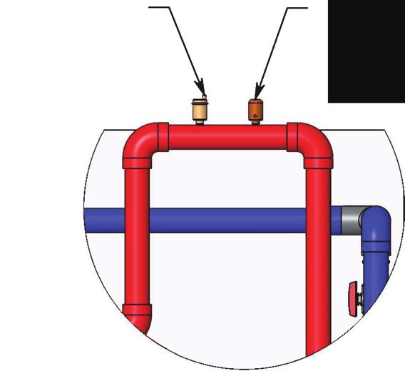
INSTALLATION GUIDE USER MANUAL SINGLE & DUAL STAGE MODELS
PIPING RECOMMENDATIONS
dŚĞdrawing on the next page shows ĨĞĂƚƵƌĞƐƚŚĂƚƐŚŽƵůĚďĞŝŶĐůƵĚĞĚŝŶƚŚĞƉŝƉŝŶŐƐLJƐƚĞŵ͘ Supplemental details
and additional recommendations are listed here:
Insulate supply and return piping
x Use closed-cell foam insulation
x Install protective cladding
DĂƚĞƌŝĂůƐ͗^ĐŚĞĚƵůĞϴϬWsŽƌ^typical for cold glycol/water systems
x Verify operating temperatures
x High temp systems may require copperor stainless steel piping
/ŶƐƚĂůůŝƐŽůĂƚŝŽŶďĂůůǀĂůǀĞƐĞdžƚĞƌŶĂůůLJĂƚĐŚŝůůĞƌƐƵƉƉůLJĂŶĚƌĞƚƵƌŶƉŽƌƚƐ
x drue union or flangedǀĂůǀĞƐĨŽƌƐĞƌǀŝĐĞĂďŝůŝƚLJ
z-ƐƚƌĂŝŶĞƌ;ϮϬŵĞƐŚͿon chiller return line
x Standard ball valve on purge line
x Additional ball valve upstream ofY-strainer for servicing
WZ
^^hZ
'h'
'ůLJĐŽůďĂĐŬĨůŽǁƉƌĞǀĞŶƚŝŽŶŵĞĂƐƵƌĞƐ͗
x ŚĞĐŬǀĂůǀĞŽŶĐŚŝůůĞƌƐƵƉƉůLJůŝŶĞ
x dǁŽŽƉƚŝŽŶƐĨŽƌƌĞƚƵƌŶůŝŶĞ͗
;ϭͿ /ŶǀĞƌƚĞĚƚƌĂƉǁŝƚŚĂŝƌǀĞŶƚǀĂůǀĞĂŶĚǀĂĐƵƵŵďƌĞĂŬĞƌ͕Žƌ
;ϮͿ
ůĞĐƚƌŽŶŝĐĂĐƚƵĂƚĞĚǀĂůǀĞ͕ǁŝƌĞĚƚŽƉƌŽĐĞƐƐƉƵŵƉƐƚĂƌƚĞƌ
,Et,
>
ŝŶĐŚŝůůĞƌĞůĞĐƚƌŝĐĂůĞŶĐůŽƐƵƌĞ
W
(/(&7521,&$&78$7('9$/9(                                 5(7851        6833/<
                                                     3,3(5('8&(5
      '(7$,/)
     6&$/(                                      &+(&.9$/9(
                                                          6&+39&3,3(
                                                             758(81,21%$//9$/9(
     758(81,21%$//9$/9(

               0(6+
I
CONTROLLER AND NAVIGATION
: UP
: ENTER
: DOWN
: ALARM
: PROGRAM
: ESCAPE
The c.pCO Mini Carel controller will display one of three icons in the bottom-right corner of its screen.
Navigate between these icons by pressing either the UP or DOWN button.
: SET
: INFO
: POWER
• Set Screen: To navigate to the set screen press either the UP or DOWN button until
is displayed on the screen. Select this option by pressing the ENTER button. Here you can see
the current numerical set point. Press the ENTER button again and the icon will begin to blink.
Now you can adjust the set point using the UP or DOWN buttons. Press the ENTER button until
the icon at the top of the screen begins to blink. Press the ESCAPE button to return to the home
screen.
• Info Screens: To navigate to the info screens press either the UP or DOWN button until
is displayed on the screen. Select this option by pressing the ENTER button. Switch between the
various info screens using the UP or DOWN buttons. Press the ESCAPE button to return to the
home screen.
• Alarm Menu: To navigate to the alarm screens press the ALARM button. Switch between alarms
by pressing either the UP or DOWN buttons. Press the ESCAPE button to return to the home
screen.
9I
c.pCO Carel Mini Alarms
Alarm Code Displayed Text Description Type Response
Check for loose connections at both sensor and
AL22 Gly. Pres. Prb Ain Err Glycol pressure sensor failure Counter 3x/10Sec controller. Replace sensor.
Glycol outlet temperature sensor Check for loose connections at both sensor and
AL23 Gly Out T. Prb Ain Err failure Counter 3x/10Sec controller. Replace sensor.
Glycol reservoir temperature sensor Check for loose connections at both sensor and
AL24 Tank Temp Prb Ain Err failure Counter 3x/10Sec controller. Replace sensor.
Verify proper glycol mixture and reservoir level. Check for
tripped/off pump breaker. Confirm proper operation of
AL25 No flow detected Glycol flow not detected Manual flow sensor.
Ensure condenser is clean, proper clearances are
adhered to, no air recirculation, and proper fan
AL26 Hi Dchrg P Circ A High discharge pressure circuit A Manual operation.
Check glycol concentration and reservoir level. Check
AL27 Lo Suction P Circ A Low suction pressure circuit A Counter 3x/30min refrigerant charge/inspect for signs of refrigerant leaks.
Check glycol concentration and reservoir level. Check
AL28 Lo Suction P Circ B Low suction pressure circuit B Counter 3x/30min refrigerant charge/inspect for signs of refrigerant leaks.
Ensure condenser is clean, proper clearances are
adhered to, no air recirculation, and proper fan
AL29 Hi Dchrg P Circ B High discharge pressure circuit B Manual operation.
Ensure that chiller is not overloaded and that no other
AL30 Hi Chill Water Temp Glycol over temperature Auto alarms are present.
Confirm that the chiller pump is operating properly, check
amperage, inspect/replace contactor, check flow sensor
Scheduled chiller pump maintenance for proper operation. Schedule technician to perform full
AL39 Chillr Pmp Maint. Sched recommended Manual chiller preventive maintenance.
Confirm that the compressor A is operating properly,
clean condenser, inspect/replace contactor, check
Scheduled compressor A amperage of fans and compressor. Schedule technician
AL40 Comp1Circ1 Maint. Sched maintenance recommended Manual to perform full compressor preventive maintenance.
Confirm that the process pump is operating properly,
check amperage, inspect/replace contactor, confirm
proper calibration of glycol pressure transducer.
Scheduled process pump Schedule technician to perform full chiller preventive
AL42 Proc. Pmp Maint. Sched maintenance recommended Manual maintenance.
Check reservoir level and glycol concentration, correct as
AL43 Low level Sensor Reservoir level too low Manual necessary. Calibrate level sensor.
Ensure that glycol temperature setpoint is in the allowed
temperature range of the chiller. Check for failed liquid
line solenoid valves and welded compressor contactors.
Extremely cold weather may also cause this alarm if there
AL44 Anti-freeze Alarm Glycol temperature too low Manual is very low load against the chiller.
Confirm that the compressor B is operating properly,
clean condenser, inspect/replace contactor, check
Scheduled compressor B amperage of fans and compressor. Schedule technician
AL45 Comp1Circ2 Maint. Sched maintenance recommended Manual to perform full compressor preventive maintenance.
Check incoming voltage for proper leg-to-leg and leg-to-
ground voltage both with chiller off and with chiller
AL47 Phase Monitor Voltage high, low, or imbalanced Auto running.
Ensure that chiller is not overloaded and that no other
AL50 Process Pmp Off Hi Temp Glycol temperature too high Auto alarms are present.
109 Easy Steps to Start-up Your New G&D Chiller
Please view install videos online at www.gdchillers.com/installation-videos
Models GD-3H through GD-7x7H
1. Chiller must be positioned with at least 24 inches of clearance on air intake side (opposite louvered
access panels) and open to free air on exhaust side (louvered panel side) with no obstructions.
2. Install Y-strainer (recommended) or purge valve on return line at chiller.
3. With the door switch in the OFF position, ensure all breakers are in the ON position. The chiller must
then be supplied with power for at least 4 hours. Verify there is a visible oil level in the compressor
sight glass before proceeding.
4. Flush all piping lines and fill reservoir with a 35% glycol to water mixture.
5. Ensure all compressor breakers are OFF.
a. Turn the door switch to RUN and verify correct pump rotation before flushing the system
b. After flushing and putting glycol in reservoir, temporarily close the supply valve and confirm
glycol pressure is at 20 PSI
6. Turn the door switch back OFF and the compressor breaker(s) back ON. Re-verify oil level in compressor
sight glass before proceeding.
7. Open all service valves in chiller marked with tags. To prevent irreversible damage, bottom valve on
compressor must be cracked back in ½ to 1 full turn after being fully opened. Contact us for more
details as needed: 800-555-0973.
8. Turn door switch to the RUN position.
9. Press arrow button until you see “Set” in the bottom right corner of the Mini Carel Display.
a. Press enter button twice
b. Use arrows to adjust set point to desired temperature
c. Press enter button
d. Press escape button
e. Verify the correct temperature is now shown after “Set:” on the home screen
PLEASE VISIT GDCHILLERS.COM TO VIEW OUR INSTALLATION VIDEOS & FAQS
*G&D Chillers welcomes any and all questions or concerns. We can be reached at 800-555-0973 or 541-345-3903
GD-9ES_3H-7x7H-r2021aWARRANTY START-UP
INSTALLATION GUIDE
CHECKLIST
• USER MANUAL SINGLE & DUAL STAGE MODELS
Jobsite: Tech Company:
Chiller Model: Technician:
Chiller Serial #: Start-Up Date:
FOLLOWING START-UP OF CHILLER, PLEASE SEND A COPY OF COMPELTED FORM TO G&D TECH SUPPORT
CLEARANCE AROUND
CHILLER
(Include picture if necessary) FRONT: BACK: LEFT: RIGHT:
GLYCOL MIXTURE
(35% or 24.75Brix)
GLYCOL LEVEL
(Reservoir % Full)
PHASE/VOLTAGE
VOLTAGE TO GROUND
(Note: High Leg to L2) L1: L2: L3:
PUMP ROTATION
GLYCOL PRESSURE
COMPRESSOR A COMPRESSOR B COMPRESSOR C COMPRESSOR D
CRANK CASE HEATER
ENGERGIZED 4 HOURS
COMPRESSOR OIL
LEVEL
L1: L1: L1: L1:
MOTOR AMPS: L2: L2: L2: L2:
L3: L3: L3: L3:
SUPERHEAT (°F)
SUBCOOLING (°F)
SUCTION PRESSURE @
30 °F GLYCOL TEMP.
DISCHARGE PRESSURE
@ 30°F GLYCOL TEMP.
PUMP #1 PUMP #2 PUMP #3 PUMP #4
L1: L1: L1: L1:
MOTOR AMPS: L2: L2: L2: L2:
L3: L3: L3: L3:
FAN MOTOR #1 FAN MOTOR #2 FAN MOTOR #3 FAN MOTOR #4
L1: L1: L1: L1:
MOTOR AMPS: L2: L2: L2: L2:
L3: L3: L3: L3:
FAN MOTOR #5 FAN MOTOR #6 FAN MOTOR #7 FAN MOTOR #8
L1: L1: L1: L1:
MOTOR AMPS: L2: L2: L2: L2:
L3: L3: L3: L3:
AMBIENT TEMP @
STARTUP
G&D CHILLERS, INC. • GD-MNL_SD_CM-R2021A
9
G&D CHILLERS, INC. 12I
SEQUENCE OF OPERATION
1. Chiller supply and return ball valves should 7. Refrigerant pressure will build and close the low
always be open during normal operation. pressure control contact. Time delay will time out
and energize compressor contactor. Compressor
2. Fluid bypass valve is factory set at 20 PSI valve
will start.
design to allow minimum flow across heat
exchanger when process is not calling for cooling. 8. High pressure control will cut power to the
compressor contact disabling the compressor if
3. Pump circulates at all times when panel door
conditions cause high head pressure.
switch is in the Run position.
9. PLC will disable the control power to compressor
4. Compressor control circuit is energized when
if leaving glycol temperature falls below low
pump is running.
temperature alarm set point.
5. If pump fails or flow fails compressor control
10. Door switch will pump down compressor then
circuit will de-energize.
turn off pump if switch is shut off during
6. Programmable logic controller (PLC) energizes compressor run cycle.
refrigerant line solenoid valves based on leaving
11. Line voltage power should be left on to main
fluid temperature.
terminal block at all times to keep crank case
heater energized during extended off cycles.
MAINTENANCE
Please contact G&D Technical Support if you have any questions or concerns regarding the performance, operation,
or maintenance of your chiller: 800-555-0973
• Refer to the separate G&D Chillers Preventive Maintenance Checklist for a complete list of maintenance tasks.
• Contract a licensed refrigeration technician to evaluate the chiller refrigeration circuit(s) regularly. These
checkups should occur annually at a minimum. Every 3-6 months is recommended.
The following tasks can be performed without the need for specialized equipment or training:
• Check glycol level and glycol/water ratio monthly. Use glycol refractometer to confirm 35% glycol mixture.
• Check compressor oil in sight glass at bottom of compressor monthly. Inspect for any oil leaks.
• Verify pump function quarterly. Confirm glycol supply pressure. Listen for abnormal sounds from the pump.
• Verify thermostat function quarterly. Check displayed temperature against a thermometer measurement.
• Condenser should be cleaned at least every 6 months for proper operation and efficiency. Use a garden hose
and spray at an angle downward.
• Lubricate fan motors every 12 months.
• See warning below. With the service disconnect in the OFF position (no power to the chiller), inspect control
panel contacts on compressor and pump contactors. Contact an electrician if replacements are needed.
WARNING: DO NOT ATTEMPT TO SERVICE ELECTRICAL COMPONENTS OR MAKE ADJUSTMENTS IN ELECTRICAL
PANEL WITHOUT PROPER TRAINING AND IMPLEMENTATION OF LOCKOUT/TAG-OUT SAFETY PROCEDURES
13INSTALLATION GUIDE • USER MANUAL SINGLE & DUAL STAGE MODELS
TROUBLESHOOTING
COMPLAINT SYMPTOMS CAUSE SOLUTION
Lower than expected suction Low refrigerant charge Check for leaks, repair, and
1 System short of and discharge pressures recharge. See item 5
capacity
Higher than expected Dirty condenser Clean. See item 2
head pressure
Lower than normal suction Incorrect superheat - Adjust superheat
pressure too high
Dirty condenser Clean condenser
2 Head pressure Tripping high pressure switch, or Condenser air short Remove obstructions,
too high compressor trips on internal
circuiting or location causes for air short circuiting
overload
too hot
Defective condenser fan Replace
motor or blade
Air or non-condensable Purge the system
gases in the system
Refrigerant over charge Remove excess refrigerant
Refrigerant leak or system Check for leaks, repair
3 Head pressure Sight glass with bubbles undercharged and recharge
too low
Plugged filter drier Replace filter drier
Insufficient subcooling Check condenser subcooling
circuit
Glycol temperature will not Excessive load on the Check load and improve
4 Suction pressure reach set point system conditions
too high TEV stuck open due to Check, repair, or re-
Incorrect superheat ice or defect place TEV
Incorrect superheat setting Adjust superheat
of the expansion valve
Sight glass with bubbles See item 3 See item 3
5 Suction pressure
Warm suction line, signs of Plugged TEV or strainer Clean TEV and strainer
too low
frost on the TEV and low
system capacity
Compressor cycling due to See item 12 See item 12
low pressure cutout
Avoid compressor short
6 Noisy Oil level below midpoint of the Lack of oil cycling or run compressor
compressor compressor sight glass during enough to return oil to
operation crankcase, correct low load
conditions. Add oil.
Noticeable knock in Worn or scored bearings Replace the compressor
compressor
Frosted suction line and Liquid flood back Check superheat and TEV
compressor shell operation
G&D CHILLERS, INC. • GD-MNL_SD_CM-R2021A
14I
TROUBLESHOOTING
COMPLAINT SYMPTOMS CAUSE SOLUTION
Minimal difference in pressure Broken suction valves Change compressor
7 Compressor does between high side and low side
Broken discharge line Change compressor
not pump of system, when compressor
motor has power Internal pressure safety Check item 13 and change
valve stuck open compressor if
necessary
Blown fuse or open disconnect Short circuit or other Check electrical circuit
8 Compressor will electrical failure and wiring
not start Tripped or damaged overload Overheating or overcurrent Wait 2-3 hours for overload
to reset and check
refrigerant charge or power
quality to the compressor
Open pressure switch Loss of refrigerant Check for leaks, repair
charge and recharge
Loose wires Vibration, bad crimping or Check terminals at
under-torque compressor, contactor and
wiring in general
Motor seized Low oil level or phase Check oil level. Restart 3-ph
reversal compressor by switching
2 phases; replace if it does not
restart
Incorrect wiring of start Check wiring
9 Compressor starts High running current, components
but start relay does overload trips Incorrect or defective Confirm operation, model
not drop out start relay and make
Incorrect or defective start Confirm integrity and
capacitor specs, check if fitted with
discharge resistance
Incorrect or defective Confirm integrity and
run capacitor specs
Low voltage Fix undervoltage protection
Excessive head pressure See item 2 above
10 Compressor Internal overload tripping due to dirty condenser
runs but cuts or lack of condenser air
out on MUST WAIT 2-3 HOURS TO or water flow
overload CHECK IF IT WILL RESET
Low voltage or unbalanced Fix undervoltage protection
Faulty electrical connections Remake the connections
causing single phasing or
high current surges
Sticking start relay on Replace relay and ensure start
single phase machines cap is fitted with a discharge
leaving start cap on circuit resistance
15INSTALLATION GUIDE • USER MANUAL SINGLE & DUAL STAGE MODELS
TROUBLESHOOTING
COMPLAINT SYMPTOMS CAUSE SOLUTION
Check for leaks, repair, and
11 Compressor starts Internal overload tripping Loss of charge causing
recharge
but cycles on insufficient motor cooling
overload MUST WAIT 2-3 HOURS TO
CHECK IF IT WILL RESET 1-ph fix undervoltage
Voltage is low or
protection, 3-ph correct
unbalanced if 3-ph
phase imbalance
Defective or wrong run
Check and replace
cap
Check current and re-
Defective overload place compressor if
necessary
…overload See items 10 and 11 See items 10 and 11
12 Compressor
Thermostat differential Check and widen differential
runs but …thermostat set too close
cycles on…
…high pressure switch See item 2 See item 2
See items 3 and 5 See items 3 and 5
---low pressure switch
Leaking liquid line solenoid Replace LLSV
valve (LLSV)
Leaking compressor Replace compressor
valves
Undercharged system Check for leaks and
recharge
Refrigerant trapped in Discharge service valve Open discharge service
13 Internal compressor closed valve
pressure
safety valve Discharge pressure exceeds high High pressure switch Reset or replace high
(IPRV) opens pressure setting malfunction pressure switch, see item 2
Too low or too high line Correct and replace relay
14 Will not start, Start relay damaged or voltage
trips on burned out
Incorrect wiring Replace relay and rewire per
overload
compressor wiring diagram
Excessive cycling See item 11
Check w/ manufacturer
Incorrect relay
15 Start Capacitor Single phase compressor will not and replace
damaged or start Too high or too low line
burned out Correct and replace
voltage
Excessive short cycling See item 11
Replace and rewire per
Incorrect wiring compressor manufacturer
wiring diagram
Wrong start or run Correct and replace
capacitor
G&D CHILLERS, INC. • GD-MNL_SD_CM-R2021A
16345367898ÿ 76 57ÿ 4ÿ
3ÿÿ 3ÿÿ !
ÿ"
ÿ $
%ÿ&
'ÿ
ÿ
ÿ #ÿ #&'ÿ
()*+ÿ ((*-ÿ .*(ÿ )+*+ÿ
()*/ÿ ((*+ÿ +*/ÿ )+*/ÿ
((*0ÿ ((*0ÿ +*+ÿ ).*-ÿ
((*.ÿ (+*-ÿ (*1ÿ ).*(ÿ
(+*-ÿ (+*2ÿ (*0ÿ ).*/ÿ
(+*+ÿ (.*-ÿ )*+ÿ )2*0ÿ
3456ÿ 3457ÿ 854ÿ 9754ÿ
(.*.ÿ (2*-ÿ -*/ÿ )2*1ÿ
(2*.ÿ (0*-ÿ :-*/ )0*.ÿ
(0*.ÿ (/*-ÿ :)*+ )/*-ÿ
(/*)ÿ (/*0ÿ :(*0 )/*+ÿ
(/*.ÿ (1*-ÿ :+*) )/*.ÿ
;INSTALLATION GUIDE • USER MANUAL SINGLE & DUAL STAGE MODELS
**TO ACTIVATE WARRANTY, FILL OUT STARTUP CHECKLIST AND RETURN WITHIN 30 DAYS**
WARRANTY STATEMENT
TWO-YEAR LIMITED WARRANTY ON PARTS, ONE-YEAR LIMITED WARRANTY ON LABOR
G&D CHILLERS, INC. provides a limited warranty to the original purchaser of new products against defects in
materials and workmanship for a period of one (1) year of normal commercial usage. For the subsequent period of
one (1) year of normal commercial usage immediately following the first, this warranty is extended to cover parts
only. This warranty is not transferable. If a product covered by this warranty is determined to be defective within
the applicable warranty periods, G&D CHILLERS, INC. will, unless otherwise required by applicable law, either repair
or exchange the product at its sole option and discretion.
EXCHANGE
Should G&D CHILLERS, INC. elect to exchange a product due to a covered defect during the warranty period, the
replacement unit may, at G&D CHILLERS, INC.’s sole option and discretion, be new or one which has been recertified,
reconditioned, refurbished or otherwise remanufactured from new or used parts and is functionally equivalent to
the original product.
REPAIR: PARTS AND LABOR
There will be no charge for parts or labor to repair a product for a covered defect during the applicable warranty
periods. Replacement parts may, at G&D CHILLERS, INC.’s sole option and discretion, be new, used, reconditioned,
refurbished or otherwise remanufactured or recertified as functionally equivalent replacement parts.
REMAINING WARRANTY
Repaired or exchanged products are warranted for the remaining portion of the product’s original warranty or for
ninety (90) days from warranty service or exchange, whichever is longer. Any upgrade to the original product will be
covered only for the duration of the original warranty period.
EXCLUSIONS
This warranty does not cover, for example: abuse, accident, acts of God, consumable parts such as batteries,
cosmetic damage (e.g. scratches, dents, cracks), damage caused by use with non-G&D CHILLERS, INC. products (e.g.
accessories, housing, parts, etc.), damages from shipping, improper installation or operation, improper voltage
supply or power surges, lack of reasonable use, misuse, modifications or alterations, normal wear and tear or aging,
as well as installation and set-up issues or any tampering or repairs attempted by anyone other than by a G&D
CHILLERS, INC. authorized repair technician. This limited warranty does not cover products sold “AS IS”, “FACTORY
RECERTIFIED”, or by a non-authorized reseller.
ASSIGNMENT OF WARRANTIES
G&D CHILLERS, INC. assigns to product purchasers any and all warranties of manufacturers and suppliers of
component parts that are assignable, but G&D CHILLERS, INC. makes no representations as to the effectiveness or
extent of such warranties and assumes no liability or responsibility for any third-party manufacturer or supplier’s
products or component parts that are sold by G&D CHILLERS, INC.
DISCLAIMER OF WARRANTY
THERE ARE NO EXPRESS WARRANTIES OTHER THAN THOSE LISTED OR DESCRIBED ABOVE. EXCEPT AS SPECIFIED IN
THIS WARRANTY SECTION, ALL EXPRESS OR IMPLIED CONDITIONS, REPRESENTATIONS, AND WARRANTIES
INCLUDING, WITHOUT LIMITATION, ANY IMPLIED WARRANTY OR CONDITION OF MERCHANTABILITY, FITNESS FOR
A PARTICULAR PURPOSE, OR ARISING FROM A COURSE OF DEALING, LAW, USAGE, OR TRADE PRACTICE, ARE HEREBY
EXCLUDED TO THE EXTENT ALLOWED BY APPLICABLE LAW AND ARE EXPRESSLY DISCLAIMED BY G&D CHILLERS, INC.
G&D CHILLERS, INC. • GD-MNL_SD_CM-R2021A
18I
TO THE EXTENT THAT ANY OF THE SAME CANNOT BE EXCLUDED, SUCH IMPLIED CONDITION, REPRESENTATION
AND/OR WARRANTY IS LIMITED IN DURATION TO THE EXPRESS WARRANTY PERIOD REFERRED TO IN THE "LIMITED
WARRANTY" SECTION ABOVE. BECAUSE SOME STATES OR JURISDICTIONS DO NOT ALLOW LIMITATIONS ON HOW
LONG AN IMPLIED WARRANTY LASTS, THE ABOVE LIMITATION MAY NOT APPLY IN SUCH STATES. THIS WARRANTY
GIVES THE CUSTOMER SPECIFIC LEGAL RIGHTS, AND THE CUSTOMER MAY ALSO HAVE OTHER RIGHTS WHICH VARY
FROM JURISDICTION TO JURISDICTION.
DISCLAIMER OF LIABILITY
G&D CHILLERS, INC.'S TOTAL LIABILITY FOR ANY AND ALL LOSSES AND DAMAGES RESULTING FROM ANY CAUSE
WHATSOEVER INCLUDING G&D CHILLERS, INC.’S NEGLIGENCE, ALLEGED DAMAGE, OR DEFECTIVE GOODS, WHETHER
SUCH DEFECTS ARE DISCOVERABLE OR LATENT, SHALL IN NO EVENT EXCEED THE PURCHASE PRICE OF THE PRODUCT.
G&D CHILLERS, INC. SHALL NOT BE RESPONSIBLE FOR LOSS OF USE, WORK STOPPAGE, FAILURE OF OTHER
EQUIPMENT TO WHICH THE PRODUCT IS CONNECTED, COMMERCIAL LOSS, LOST REVENUE OR LOST PROFITS, LOSS
OF GOODWILL, LOSS OF REPUTATION, OR OTHER INCIDENTAL OR CONSEQUENTIAL DAMAGES. NO ORAL OR
WRITTEN REPRESENTATIONS MADE BY G&D CHILLERS, INC. SHALL CREATE ANY ADDITIONAL WARANTY
OBLIGATIONS, INCREASE THE SCOPE, OR OTHERWISE MODIFY IN ANY MANNER THE TERMS OF THIS LIMITED
WARRANTY. TO THE EXTENT PERMITTED BY APPLICABLE LAW, G&D CHILLERS, INC. DOES NOT WARRANT THAT THE
OPERATION OF ANY PRODUCTS COVERED UNDER THIS LIMITED WARRANTY WILL MEET YOUR REQUIREMENTS, OR
THIRD PARTY SERVICES, BE UNINTERRUPTED, ERROR-FREE, OR THAT DEFECTS IN THE PRODUCTS WILL BE
CORRECTED. SOME STATES DO NOT ALLOW THE EXCLUSION OF INCIDENTAL OR CONSEQUENTIAL DAMAGES, SO THE
ABOVE LIMITATIONS OR EXCLUSIONS MAY NOT APPLY TO YOU. THIS WARRANTY GIVES YOU SPECIFIC LEGAL RIGHTS,
AND YOU MAY ALSO HAVE OTHER RIGHTS, WHICH VARY FROM STATE TO STATE. THIS LIMITED WARRANTY IS
SUBJECT TO CHANGE WITHOUT NOTICE. CHECK www.gdchillers.com FOR THE MOST CURRENT VERSION OF THIS
WARRANTY.
SEVERABILITY
In the event that any term or provision contained in this limited warranty is found to be invalid, illegal or
unenforceable by a court of competent jurisdiction, then such provision shall be deemed modified to the
extent necessary to make such provision enforceable by such court, taking into account the intent of the
parties. The invalidity in whole or in part of any portion of this limited warranty shall not impair or affect
the validity or enforceability of the remaining provisions of this limited warranty.
HOW TO OBTAIN WARRANTY SERVICE (PRE-AUTHORIZATION REQUIRED)
To obtain warranty service, contact G&D CHILLERS, INC.:
1. Email: info@gdchillers.com
2. Phone: (800) 555-0973 from 9:00AM to 5:00PM Monday through Friday Pacific Time.
3. By mail: G&D Chillers, Inc.
760 Bailey Hill Rd
Eugene, OR 97402
19INSTALLATION GUIDE • USER MANUAL SINGLE & DUAL STAGE MODELS
G&D Chillers welcomes any and all questions or concerns
We can be reached at 800-555-0973 or 541-345-3903
G&D CHILLERS, INC. • GD-MNL_SD_CM-R2021A
20You can also read