Daikin One+ smart thermostat Reference Guide for Unitary Equipment
←
→
Page content transcription
If your browser does not render page correctly, please read the page content below
Daikin One+ smart thermostat
Reference Guide for
Unitary Equipment

Software Version: v2.1.16
WARNING
Only personnel that have been trained to install, adjust, service
or repair (hereinafter, “service”) the equipment specified in this
manual should service the equipment. The manufacturer will not
be responsible for any injury or property damage arising from
improper service or service procedures. If you service this unit,
you assume responsibility for any injury or property damage
which may result. In addition, in jurisdictions that require one or
more licenses to service the equipment specified in this manual,
only licensed personnel should servise the equipment.
Improper installation, adjustment, servicing or repair of the
equipment specified in this manual, or attempting to install,
adjust, service or repair the equipment specified in this manual
without proper training may result in product damage, property
damage, personal injury or death.

                  PROP 65 WARNING
             FOR CALIFORNIA CONSUMERS

                            WARNING
                 Cancer and Reproductive Harm -
                   www.P65Warnings.ca.gov
                                                        0140M00517-A
TABLE OF CONTENTS
INTRODUCTION
 Features and Benefits.....................................................................6
 How to Use the Quick Reference Cards.........................................8
 Equipment Compatibility ................................................................9
 Installing the Daikin One+ smart thermostat................................10
 Wiring Thermostat to Communicating Systems........................... 11
 Wiring Diagrams............................................................................ 12
 How to Wire a Humidifier to Daikin furnace................................. 17
 Wiring Troubleshooting.................................................................18
SYSTEM POWER-UP
 System Power-up Sequence.........................................................29
 Commissioning the Daikin One+ smart thermostat.....................30
   Begin Set-up..............................................................................31
   Step 1 – Communication.......................................................32
   Step 2 – Personalization........................................................33
   Step 3 – Equipment Set-up....................................................34
             How to Configure Humidifier on
             Modulating and 2-stage Furnaces.............................35
             How to Configure Heat Kit.........................................35
             How to Set-up Lockout
             Temperature for Heat Pump......................................37
   Step 4 – System Optimization..............................................38
             How to Run System Test for
             Inverter Outdoor Units...............................................39
             How to Use Charge Mode.........................................40
             How to Calibrate Temperature................................... 41
             How to Check Error History.......................................42
             How to Check System Operational Information...........43
   Step 5 – Preferences...............................................................44
             How to Create Reminder...........................................45
 Dealer Navigation (How to return to Dealer Edit Mode)..........................46
 How to Set-up Humidification
 and Dehumidification Set-points...................................................48

REFERENCES
 FAQs..............................................................................................52
 Support and Resources.................................................................54
 Menu Outline Table of Contents...................................................55
 Menu Outline Overview................................................................56
 Important Notes............................................................................85

                                                                                                        3
Introduction

Features and Benefits
Designed with quality components
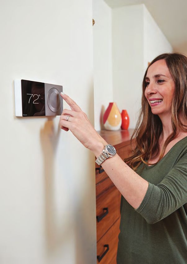
1 The high-resolution color touch screen display is protected
by the same toughened glass used in smart phones.
2 The anodized aluminum bezel and dial are precision manufactured.
The surfaces have a fine bead blast with a warm hued anodized
finish. The dial rotation is extraordinarily smooth because it rests on
a bearing assembly typically found in precision instruments. A switch
behind the dial enables users to return to the home screen from
any menu with a single tap.
3 An integrated Wi-Fi radio connects to the internet (via a home
router) to the cloud and onto the homeowner mobile application.
The Daikin cloud will also seamlessly integrate with open smart
home architectures, including Amazon Alexa and Google Assistant,
enabling consumers to effortlessly use features such
as voice control.
4 A thin LED light bar sits flush within the bottom surface and
runs from edge to edge, delicately illuminating the wall beneath.
Emitting a soft emotive glow, the light bar indicates the current
system mode: red for heating, blue for cooling.
5 Built-in bubble level aids professional installation
- See page 85 for important notice concerning FCC
6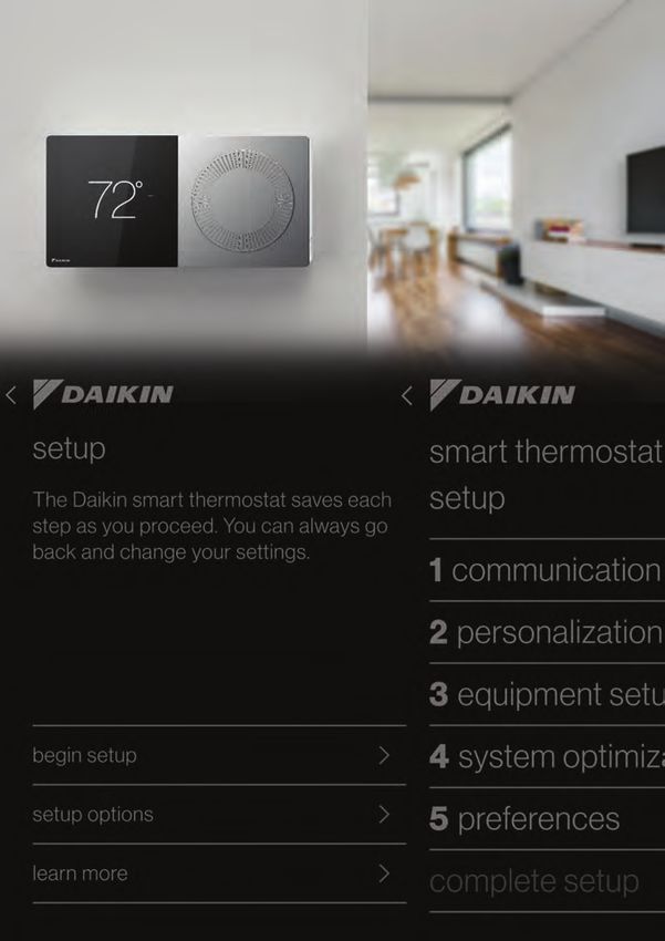
A number of screen              Turning the dial

                                                           INTRODUCTION
1   savers are available,   2       changes the
    including this                  temperature
    analog clock.                   set-point.

    3

    4
                                5

                                                       7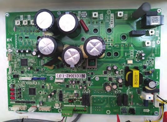
How to Use the Quick Reference Cards

There are quick reference cards packaged with the Daikin One+ to help
answer questions during the installation and commissioning.

          Scanning the bar code on the bottom left corner will
          link you to a website related to the title of the card.

     For further details on the Quick Reference Cards refer to page 86, or visit
            https://www.daikinone.com/smart_thermostats/oneplus

 8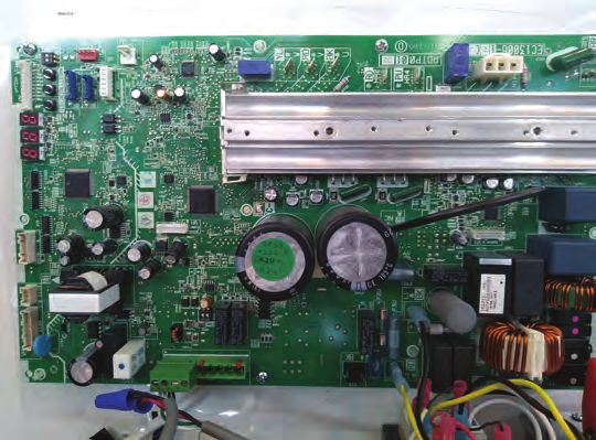
Equipment Compatibility

The Daikin One+ offers two-way communication when combined with
Daikin’s smart inverter HVAC systems, serving as a cloud-connected hub

                                                                                                             INTRODUCTION
and controller for communicating HVAC systems.

                                                                Indoor Unit
                                                 Furnace         Coil             Air Handler/Blower
                                                      DM96VC
                                                      DC96VC                                     DVPVC
                                           DM97MC    DM96SC-U   CAPE
                                                                         DVFEC         DVPEC     DVPTC
                                           DC97MC     DM80VC    CHPE
                                                      DC80VC                                     MBVC
                                                     DM80SC-U

                                 DX20VC      √             √     –            –          √         √
               Air Conditioner

                                 DX17VSS     √             √     √            –          –         √
                                 DX18TC      √             √     –            –          –         √
                                 DX16TC      √             √     –            –          –         √
Outdoor Unit

                                 DZ20VC      √             √     –            –          √         √
                                             –             –     –            –          √         –
               Heat Pump

                                 DZ18VC
                                 DZ18TC      √             √     –            –          –         √
                                 DZ17VSA     √             √     √            √          –     √(MBVC)
                                  DZ16TC     √             √     –            –          –        √
                     24 VAC Condenser        √             √     –            –          –        –
24 VAC Condenser (Legacy 24V) is compatible only with communicating furnace

                                                                                                         9
Installing the Daikin One+ smart thermostat
» Mounting the thermostat will be leveled:
   – Approximately 5’ from the floor.
   – On an interior wall using the included screws.
   – There are two options for mounting:

       Standard Surface Mount                       Optional Flush Mount*

The Daikin One+ smart thermostat comes      The Daikin One+ smart thermostat also
with an attractive surface mount and trim   offers a flush mount* installation option
bezel as standard.                          to provide homeowners with a modern
                                            built-in style option.

                                °
Use included screws          72

» You do not need the trim plate to         » A template for marking a drywall
  mount the thermostat.                       cutout is included.
» Screws included are designed to           » Use a stud and wire finder to verify the
  mount in sheetrock or studs                 thermostat can be placed in desired
» Its recommended to use the screws           location on the wall.
  provided with Daikin One+ packaging       » Allow a minimum 1 inch clearance
  for best results                            between the desired location and stud
                                              for tightening and leveling purposes.

                                            *NOTE: Available early 2021 -
                                            Requires Kit # DKIT-FLSH-ONE

 10
Wiring Thermostat to Communicating Systems
INTRODUCTION
» Maximum wire distance between the Daikin One+ and the
indoor unit should not exceed 125 feet using 18-gauge solid
core wire.
» For installing the Daikin Fit outdoor system, it is strongly
recommended (for best results) to use 18-gauge solid
core wire.
» Check for proper voltage before and after wiring
is installed.
– 0.6 VDC between Data 1 and 2
– 24 VAC between common and power
» Wiring communicating indoor unit to communicating
outdoor units.
– Connect 1, 2, C and R from the Daikin One+, to 1, 2, C
and R at the indoor unit.
– Connect wires 1 and 2 from the indoor unit to 1 and 2
at the outdoor unit.
» Wiring communicating indoor furnace unit to non-communicating
outdoor units.
– Connect 1, 2, C and R from the Daikin One+, to 1, 2, C and R
at the indoor furnace unit.
– Connect wire Y1 from the indoor furnace unit to Y1 at
the outdoor unit
– Under Equipment Setup add ‘24 VAC Condenser’.
– Under ‘24 VAC Condenser’ select the matching kBTU
from ‘cool CFM’ settings
11Wiring Diagrams
1 2 C R
Daikin One+
DE
9 pin R C G W1 W2 Y1 Y2 O HUM
DE
Indoor Unit 1 2 R C G W1 W2 Y1 Y2 O HUM
7 pin R C W1 Y1 Y2 L O
Outdoor Unit 1 2 R C W1 Y1 Y2 L O
» Communicating indoor units supplied with
a 9 pin connector only, will move the
connector to the far left to pair R, C, G,
W1 on the 9 pin with 1, 2, R, C on the
indoor PCB.
» Communicating outdoor units supplied with a
7 pin connector only, will move the connector
to the far left to pair R, C on the 7 pin with
1, 2 on the outdoor PCB.
Note: The Daikin One+ is labeled 1, 2, C, R.
If wired incorrectly you will receive a
communication error, or your equipment may
not be recognized and displayed.
121 2 C R
INTRODUCTION
Daikin One+
4 pin 1 2 R C
DE
Indoor Unit 1 2 R C G W1 W2 Y1 Y2 O HUM
4 pin 1 2 R C
Outdoor Unit 1 2 R C W1 Y1 Y2 L O
» Communicating indoor units with a 4 pin
connector supplied, will match 1, 2, R,
C on the 4 pin with 1, 2, R, C on the
indoor PCB.
» Communicating outdoor units with a
4 pin connector supplied, will match
1, 2 on the 4 pin with 1, 2 on the
outdoor PCB.
Note: The Daikin One+ is labeled 1, 2, C, R.
If wired incorrectly you will receive a
communication error, or your equipment may
not be recognized and displayed.
13Wiring Diagrams 14
Communicating FIT System with AHU
Plug & Play System; Only four wires required to connect each component

                                                                                       INTRODUCTION
 Communicating        Compatible Communicating              Daikin One+
 OUTDOOR UNIT              INDOOR UNIT                    Smart Thermostat
   (DX17VSS)

   1                             1                                  1
   2                             2                                  2
   R                            R                                   C
   C                            C                                   R

Note: It is required to use a minimum of 18-Gauge wire.
      Maximum operating length of wire is 125 ft.                     7/24/2019

                                                                                  15
Wiring Diagrams 16
How to Wire a Humidifier to Daikin Furnace

                                                                   INTRODUCTION
                                         HUM-OUT

                                                   HUM-IN
                     NEUTRAL

                            HUMIDIFIER
                                                      L1

                                         HUM-OUT

                                                   HUM-IN
                     24 VOLT
                    COMMON

                            HUMIDIFIER
                                                       R

» The indoor furnace control is equipped with a dedicated
  humidification relay which is available through ¼ inch
  terminals HUM-IN and HUM-OUT
» HUM-IN must be powered with the desired voltage
  (24 VAC from the R terminal or 115 VAC from L1 terminal)
» Humidification relay turns ON when there is call for heat
  and a call for humidification
» For 2-stage furnace only, humidifier relay supports
  below modes
  – ON: Humidifier is turned on with a heat demand
    and humidification demand
  – OFF: Humidifier remains off (relay never closes).

                                                              17
Wiring Troubleshooting
The following steps require no power to be applied.
– Check for any loose, disconnected, broken, or shorted wires
between all connected components BEFORE applying power
– No short between Data 1 or Data 2 wires and R (24 VAC) or C (24
VAC common)
– Check for Data 1 and Data 2 wires reversed at the indoor unit,
thermostat, or outdoor unit
After fixing all the wiring issues apply power
– Check for 24 VAC across R (24 VAC) and C (24 VAC common)
terminals
– If there are still problems discovering the indoor or outdoor
equipment then check for bias reading of 0.6 VDC. Bias reading
of 0.6 VDC indicates a robust network that can handle high data
volume without lock-up.
0.6 VDC
NOTES: If Bias reading is below 0.6 VDC, check the TERM Dip-Switch (DS1) setting
on the outdoor unit. Move the TERM Dip-Switch (DS1) to OFF Position. This
should improve the Bias reading to 0.6 VDC
18– Follow the steps below to measure and achieve 0.6 VDC bias value.
– Turn OFF the thermostat and make sure the system is idle
INTRODUCTION
– Take Bias readings on the outdoor Heat Pump or Air Conditioner
– Measure DC voltage between 24 VAC common to Data 1 = D1 VDC
– Measure DC voltage between 24 VAC common and Data 2 = D2 VDC
– Bias reading = D1 VDC – D2 VDC (Subtract D2 from D1 to calculate bias voltage)
= 0.61 VDC
– Measure DC voltage between Data 1 and Data 2. This value should
equal the value calculated in the previous step.
– Take Bias readings on indoor Air Handler or Furnace by repeating
above steps on its terminal blocks.
– Take Bias readings on CAPE EEV coil if connected by repeating above
steps on its terminal blocks.
– The Bias readings should match on all the equipment's terminal
blocks.
– If Bias reading is below 0.6 VDC, check the TERM Dip-Switch (DS1)
setting on the outdoor unit. Move the TERM Dip-Switch (DS1) to OFF
position. This should improve the Bias reading to 0.6 VDC.
– After stabilizing the network, power down the entire HVAC system.
Wait for a few minutes and power back up. It will take approximately
3-5 minutes for the HVAC system and thermostat to discover the
indoor and outdoor equipment.
For a view of the DS1 switch on the outdoor
unit PC boards, see pages 20-24.
1. 17 SEER Daikin Fit
2. 18 SEER (all tonnage)
3. 20 SEER (2 and 3 Ton)
4. 20 SEER (4 Ton)
5. 20 SEER (5 Ton)
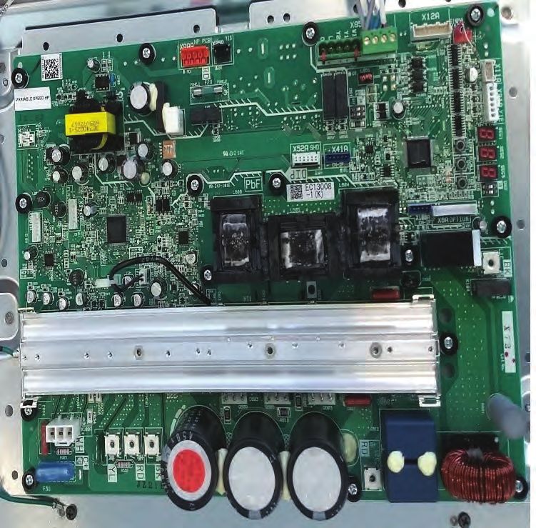
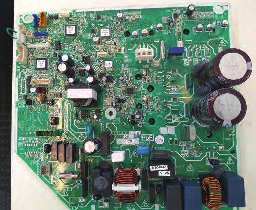
19Wiring Troubleshooting
View of the DS1 Switch on the Outdoor Unit PC Boards
1. 17 SEER Daikin Fit
202. 18 SEER (all tonnage)
INTRODUCTION
21Wiring Troubleshooting
3. 20 SEER (2 and 3 Ton)
224. 20 SEER (4 Ton)
INTRODUCTION
23Wiring Troubleshooting
5. 20 SEER (5 Ton)
24System Power-Up
System Power-up Sequence

Follow the instructions to wire the Daikin One+
smart thermostat with the communicating indoor
and outdoor systems.

Mount the thermostat and power ON the indoor and
outdoor units. The Daikin One+ smart thermostat
gets power from the indoor unit.

Follow the steps mentioned under Commissioning
Daikin One+ to configure the indoor unit and
outdoor unit.

                                                       SYSTEM POWER-UP

                                                  29
Commissioning the Daikin One+ smart thermostat
Begin set-up
» The welcome screen displays basic instructions upon powering the
thermostat. Select the right language and "use large font” if desired,
then click continue.
» Select the right equipment type. Unitary is the default, so just click
continue if you have unitary eqipment.
» An explanation of two set-up options is displayed on the learn
more screen.
» Demo mode displays a quick video of the Begin set-up and a few
homeowner navigation features.
1
2
30Begin set-up
» Tapping Begin set-up starts the 5 step set-up process:
1. Communication.
2. Personalization.
3. Equipment Set-up.
4. System Optimization.
5. Preferences.
» Begin set-up ensures the system is configured properly and ready
for the homeowner to use.
Note: All of the 5 steps must be completed and reviewed before you
can complete the set-up.
SYSTEM POWER-UP
31Commissioning the Daikin One+ smart thermostat Begin set-up Step 1 – Communication » Configures Communication Networks. » Select home Wi-Fi to search for networks. » With Wi-Fi configured, the system can check the software version and update software to the latest version automatically. 32
Begin set-up
Step 2 – Personalization
» Tapping the personalization tab allows you to edit default
  information.
» Personalization displays:
  – Language.
  – Use Large Font.
  – Date & Time.
    – If Wi-Fi is connected, date & time set automatically.
  – Thermostat Name.
  – Degree Units.

Note: Tapping Daikin logo returns to welcome screen

                                                                    SYSTEM POWER-UP

                                                               33
Commissioning the Daikin One+ smart thermostat
Begin set-up
Step 3 – Equipment set-up
» Displays equipment found by searching the communication network, or
by adding/removing equipment and accessories from the preset list.
» There are options to view and optimize settings that apply to the
installed units.
– View unit Specifications.
– Configure
– Cool settings
– Heat Settings
– Heat Pump Settings
– Humidifier Relay
– Aux alarm
– Heater Kit
Reference to Menu Outline
» For a detailed view of menu and sub-menu settings, refer to the Menu
Outline Overview on pages 55-64 or visit https://daikinone.com/smart_
thermostats/oneplus/pros/ DaikinOnePlus-CommissioningMenuOutline.pdf
» Menus and sub-menus will display or not depending on the type of
indoor and outdoor units detected.
34Begin set-up
How to Configure Humidifier on Modulating and
2-stage Furnaces
» Refer to the Humidifier in the furnace section under Installing
Daikin One+ section for details on wiring humidifier to the furnace board
» For 2-Stage furnace, Daikin One+ supports ‘humidifier relay’
settings. It has the following options:
– ON: Humidifier is turned on with heat demand
& humidification demand
– OFF: Humidifier remains off (relay never closes).
» For Modulating furnace, humidifier is turned ON with heat demand
& humidification demand.
How to Configure Heat Kit
Heater kit configuration varies based on the type of the Indoor units.
SYSTEM POWER-UP
DVPVC, DVPTC, MBVC
» Use dip switches on the board
to configure the heater kit size.
Please refer to the installation
manual of these boards to locate
the dip switches.
» Heater kit size configured with
dip switches will appear under
Installer Wizard > equipment setup
> air handler > heater kit > size (kW)
Enable ‘heater kit installed’ checkbox.
Installer Wizard > equipment setup
> air handler > heater kit installed
» ‘heater kit’ sub-menu
appears on enabling ‘heater
kit installed’ checkbox
» Inside ‘heater kit’ sub-menu ‘heat
airflow trim’ value can be adjusted
35Commissioning the Daikin One+ smart thermostat Begin set-up DVPEC/DVFEC Some details have advanced settings. » Navigate to heater kit size sub-menu under the Air Handler Installer Wizard > equipment setup > air handler > heater kit > size (kW) > Select the heater kit size by scrolling available ‘size(kW)’ options. » If required, adjust ‘electric heat airflow trim’ Installer Wizard > equipment setup > air handler > heater kit > electric heat airflow trim 36
Begin set-up

How to Setup Lockout Temperature for Heat Pump
Heat pump settings allow for adjustment of compressor lockout
temperature and auxiliary (secondary) lockout temperature
ELECTRIC BACKUP HEAT
» Auxiliary heat lockout temperature:
  – Auxiliary electric strip heat won’t run
    above this outdoor temperature.
  – Must be at least 10°F greater than heat
    pump lockout temperature.
    Installer Wizard > equipment setup >
    heat pump > heat pump settings > aux
    heat lockout temp
» Heat pump lockout temperature:

                                                                            SYSTEM POWER-UP
  – The heat pump compressor won’t run
    below this outdoor temperature.
  – Must be at least 10°F less than aux heat
    lockout temperature.
    Installer Wizard > equipment setup
    > heat pump > heat pump settings >
    heat pump lockout temp
When the outdoor temp is between the heat
pump lockout and aux lockout temperatures
  – Backup heat is requested immediately
    if the difference between the heat set-
    point and indoor temperature is greater
    than 4°F
  – Depending on load conditions and system performance, the
    thermostat will wait to request backup heat. Backup heat will only be
    requested when the temperature is not rising to meet the heat set-
    point in a reasonable amount of time.
DUAL-FUEL BALANCE POINT:
» Balance point lockout temperature:
  – The heat pump will only turn on above this lockout temperature.
  – A gas furnace will only turn on below this lockout temperature.
  – Heat pump lockout temperature is not required on a dual fuel system.

                                                                       37
Commissioning the Daikin One+ smart thermostat
Begin set-up
Step 4 – System Optimization
System optimization displays:
» System test. » Optional test
– Inverters only » Error history
» Charge mode – Logs alerts with an error code
– Inverters only – White = not critical
– Yellow = critical
» Calibration
» Status
38Begin set-up
How to Run System Test for Inverter Outdoor Units
Navigate to system optimization > system test > Inverters only
» On initial power-up the inverter heat pump or air conditioner will
display code E11, signaling that initial system test must be run.
» System test is required to check the equipment settings and functionality.
» Once selected, it checks the equipment for approximately 10-15
minutes. System test may exceed 15 minutes if there is an error.
» While the system test is active “test running” message shows
up on the screen.
» System test is complete only when display code E11 notice clears
from the seven segment LED display on the heat pump or air
conditioner. Please wait for test to complete and for code to clear.
» As soon as the test completes, “test running” message is cleared
SYSTEM POWER-UP
from the screen.
39Commissioning the Daikin One+ smart thermostat
Begin set-up
How to Use Charge Mode
Navigate to system optimization > charge mode > run test
» Charge mode allows for the contractor/technician to monitor system
performance and top off the charge if needed.
» System operates for a duration of approximately one hour while the
equipment runs at full capacity.
» During this time, the contractor/technician will add vapor refrigerant
into the suction line while monitoring system performance.
Refrigerant should no longer be charged into the system once
performance is correct.
» After one hour, the charge mode ends and the system resumes
normal thermostat operation.
» To terminate charge mode select ‘stop’.
FOR PROPER CHARGING OF A SYSTEM, SEE EQUIPMENT
INSTALLATION MANUAL.
40Begin set-up
How to Calibrate Temperature
Navigate to system optimization > calibration > temperature calibration
» To calibrate or make adjustment to the thermostat displayed
temperature drag the offset up or down.
» Adjustment can be made -7°F to +7°F in 1°F steps.
SYSTEM POWER-UP
41Commissioning the Daikin One+ smart thermostat Begin set-up How to Check Error History Navigate to system optimization > error history » Daikin One+ “error history” menu provides access to the most recent equipment and system errors. » Errors are stored in order from most recent to least recent. » Each error entry comprises an error code, the equipment type which generated the error, brief error description and a timestamp. » Critical errors are displayed with an alert icon with a yellow head. » Any consecutively repeated error is stored only once. » For more information please refer to Daikin One+ communicating thermostat documentation. Critical errors are displayed with an alert icon with a yellow head. 42
Begin set-up
How to Check System Operational Information
Navigate to system optimization > status
» The status menu displays data pertaining to the selected equipment
» The scrollable list can be accessed any time by returning to the
  installer set-up screen

                                                                          SYSTEM POWER-UP

                                                                     43
Commissioning the Daikin One+ smart thermostat Begin set-up Step 5 – Preferences There are four preference settings to choose from in order to optimize your systems performance. » Cool/Heat » House settings » Dealer information » Reminders Note: Changing preferences is not required, but reminders and dealer contact information should be input. 44
Begin set-up
How to Create Reminder
» The number of reminders are
  based on the installed equipment with accessories.
» Once the equipment has been added, a 1 – 24 month service reminder
  can be selected for the installed equipment.
Note: The homeowner cannot edit service reminders.

                                                                       SYSTEM POWER-UP

                                                              45
Dealer Navigation How to return to Dealer Edit mode (Begin set-up) Navigating to dealer edit will allow you to access or revisit the installer set-up screen. » Advanced adjustments to the Daikin One+ will be made here. 46
SYSTEM POWER-UP

                  47
How to Set-up Humidification and Dehumidification Set-points On the homeowner menu navigate to settings > comfort > target humidity » Drag the value left or right to set the target humidity level » Top value displays the target humidification level » Bottom value displays the target dehumidification level » The system attempts to keep the humidity as close as possible to your selected value 48
References
FAQs

  1. What are the support resources available?
 1. a. For general support for the Daikin One+ smart thermostat –
  		 call 1-855-daikin1 and select option #1.
 2. b.       For troubleshooting* and error codes – call 1-855-daikin1
  		         and select option #4 (*For optimal support experience,
  		         dealers/installers must be on site before calling our
  		         troubleshooting lines).
 3. c. www.Daikinone.com has resources for homeowners
  		 and professionals.
 4. d. For questions on where to find educational materials - call
  		 1-855-daikin1 and select option #6.
 5.e. Technical specifications and training content can be found
  		 on www.DaikinCity.com.
  2. What to do if equipment isn't found during discovery mode?
           a. Find the AHU but not the outdoor unit?
             i.   Ensure wiring is tight, as this may cause dysfunctional
           		     systems due to loose wiring at the One+ mounting plate.
           		     Reference back to the wiring troubleshooting section
           		     (page 18).
  3. How do I connect to Wi-Fi?
 6. a.       You can connect the Daikin One+ smart thermostat
  		         to Wi-Fi by following the steps below. If you have
  		         more than one thermostat each one will need to be
  		         connected individually.
 7. i. Select the menu icon located in the upper right-hand
  		 corner section.
 8.           ii. Select Settings and then Configuration.
 9.           iii. Then select Home Wi-Fi.
10. iv. Ensure the “Use Wi-Fi” box is checked and then
  			 select scan network.

      52
REFERENCES
53Support and Resources
If you encounter any issues or would like assistance with setting up
your Daikin One+ smart thermostat:
CONTACT DAIKIN SUPPORT AT 1-855-DAIKIN1 AND SELECT
OPTION ONE TO BE CONNECTED WITH OUR SUPPORT TEAM
Other resources:
– Go to www.daikinone.com and click on the banner to access
homeowner site and dealer site for Daikin One+
» Homeowner
– Welcome page:
https://www.daikinone.com/smart_thermostats/oneplus/welcome/
– Contains information for homeowner for how to use Daikin
One+ smart thermostat and how to use the mobile app
» Professional (Contractor/Installer)
– Get help at www.daikinone.com/smart_thermostats/oneplus/Pros
– Installation and commissioning information
– Commissioning menu outline
– Wiring diagram, troubleshooting table
» Daikin One+ Installation and Commissioning webinar is also
available from Daikin City > Daikin University
– https://youtu.be/_3q_UhF84Xs
– https://www.youtube.com/user/DaikinAC
54Menu Outline Table of Contents
» Daikin One+ Smart Thermostat Commissioning Menu Outline
for Unitary equipment
– v2.1.16 software
WELCOME................................................................................... 56-57
EQUIPMENT TYPE..................................................................... 56-57
SETUP......................................................................................... 56-57
1. COMMUNICATION................................................................. 56-57
2. PERSONALIZATION............................................................... 58-59
3. EQUIPMENT SETUP...............................................................60-75
4. SYSTEM OPTIMIZATION.......................................................74-81
5. PREFERENCES........................................................................ 80-83
REFERENCES
55Menu Outline Overview
Level 1 Level 2 Level 3 Level 4 Level 5
english
español (radio buttons)
française
welcome
use large font (checkbox)
continue
unitary (radio button)
single/multi-split
(S21) (radio button) cancel
continue
Equipment Type
VRV, SkyAir, single/
multi-split (P1P2)
(radio button)
continue
(to smart thermostat
begin setup setup with 5 main
steps below)
factory reset
run dealer demo
setup options mode
run homeowner demo
mode
Setup
learn more
unitary
mini/multi-split (S21)
equipment type
VRV, SkyAir, mini/
multi-split (P1/P2)
use wifi
(list of available
networks networks)
1. Communication
search again
home wifi
internet connected
(tickmark)
Daikin One Cloud
connected (tickmark)
56Level 6 Default Display only? Conditions
english
unchecked
unitary
unitary
REFERENCES
Only appears when “use wifi”
selected
Only appears when connected to
Yes
acive wifi network.
Only appears if successfully
Yes
connected to internet.
Continued on next page
57Menu Outline Overview
Level 1 Level 2 Level 3 Level 4 Level 5
english
language español
française
use large font (checkbox)
(month, day, and year
selection)
(hour, minute, and
date & time am/pm selection)
use 24-hour format
time zone (list of time zones)
main room
upstairs
downstairs
hallway
device name (text entry for other)
bedroom
2. Personalization
kitchen
other
(other name)
fahrenheit
degree units
celsius
58Level 6 Default Display only? Conditions
english
unchecked
set automatically when connect
to WiFi.
set automatically when connect
to WiFi.
disabled
set automatically when connect to
Pacific
mobile app.
main room
fahrenheit
REFERENCES
Continued on next page
59Menu Outline Overview
Level 1 Level 2 Level 3 Level 4 Level 5
Model #
Serial #
Control Software
Version
Inverter Software
Specifications
Version
Number of cool stage
Number of heat
stages
Tonnage
Low speed trim
Intermediate speed
trim
Cool Airflow Trim
Air Conditioner
High speed trim
(model # from CT)
-10% to 10% in
2% increments
Profile A
Profile B
Cool Profiles
Cool Settings Profile C
Profile D
Cool Airflow
5, 10, 20, 30s
ON Delay
Cool Airflow
30, 60, 90, 120s
OFF Delay
3. Equipment Setup
Max compressor RPS
0 to 20 in
RPS offset
0.5 RPS steps
Dehumidify with
Dehumidification
cooling:
60Level 6 Default Display only? Conditions
Yes If scan successful
Yes
Yes
Yes Inverter only
Yes
Yes Will display for AC, as “0” stages.
Yes
-15% to 15% in
Inverter AC only
3% increments
-15% to 15% in
Inverter AC only
3% increments
-15% to 15% in
Inverter AC only
3% increments
2-stage models only
Yes Inverter only
REFERENCES
Inverter only
Off, On
Continued on next page
61Menu Outline Overview
Level 1 Level 2 Level 3 Level 4 Level 5
Model #
Serial #
Control Software
Version
Inverter Software
Specifications
Version
Number of cool stage
Number of heat
stages
Tonnage
Low speed trim
Intermediate speed
trim
Cool Airflow Trim
Heat Pump
High speed trim
(model # from CT)
-10% to 10% in
2% increments
Profile A
Profile B
Cool Profiles
Cool Settings Profile C
Profile D
Cool Airflow
5, 10, 20, 30s
ON Delay
3. Equipment Setup cont'd
Cool Airflow
30, 60, 90, 120s
OFF Delay
Max compressor RPS
0 to 20 in
RPS offset
0.5 RPS steps
Dehumidify with
Dehumidification
cooling:
62Level 6 Default Display only? Conditions
Yes
Yes
Yes
Yes Inverter only
Yes
Yes
Yes
-15% to 15% in
Inverter HP only
3% increments
-15% to 15% in
Inverter HP only
3% increments
-15% to 15% in
Inverter HP only
3% increments
2-stage models only
Yes Inverter only
REFERENCES
Inverter only
Off, On
Continued on next page
63Menu Outline Overview
Level 1 Level 2 Level 3 Level 4 Level 5
Low speed trim
Intermediate speed
trim
Heat Airflow Trim
High speed trim
-10% to 10% in
2% increments
Heat Airflow ON
5, 10, 15s
Delay
Heat Airflow OFF
30, 50, 70, 90s
Delay
Heat Settings
1: always on; 2: on
below 30°F; 3: 35°F;
Heat Pump
4: 40°F; 5: 45°F;
(model # from CT) Backup Defrost Heat
6: 50°F; 7: 55°F; 8:
cont'd
60°F; 9: 65°F; 10:
always off;
Defrost Interval 30, 60, 90, 120m
Defrost Compressor
0, 5, 15, 30s
Delay
Max compressor RPS
0 to 20 in 0.5 RPS
Max RPS offset
3. Equipment Setup cont'd
steps
heat pump lockout -20°F to 65°F in
temp 5°F increments
Heat Pump Settings aux heat lockout
temp -10°F to 75°F in
-or- 5°F increments
balance point
64Level 6 Default Display only? Conditions
-15% to 15% in
Inverter HP only
3% increments
-15% to 15% in
Inverter HP only
3% increments
-15% to 15% in
Inverter HP only
3% increments
2-stage models only
HP only
HP only
Fit Heat Pump only
HP only
2-stage HP only
Yes Inverter only
Inverter only
If also electric or gas heat.
15°F
Not displayed for dual-fuel systems.
If also electric or gas heat, "balance
50°F
REFERENCES
point" is for dual-fuel systems.
Continued on next page
65Menu Outline Overview
Level 1 Level 2 Level 3 Level 4 Level 5
Model #
Serial #
Control Software
Version
Specifications
number of furnace
stage
Size/Capacity
Blower Motor Size
-15% to 15% in
3% increments
Gas Heat Airflow Trim
-10% to 10% in
2% increments
Furnace
(model # from CT) Gas Heat Airflow 5 to 30s in
ON Delay 5s increments
Heat Settings
Gas Heat Airflow 30 to 180s in
OFF Delay 30s increments
Tap A
Tap B
Heat CFM Taps
Tap C
Tap D
3. Equipment Setup cont'd
Humidification Mode On, Off
Humidifier Relay
Humidification Fan
25, 50, 75, 100%
Speed
Aux Alarm On/Off
66Level 6 Default Display only? Conditions
Yes
Yes
Yes
Yes
Yes
Yes
Modulating furnace only
2-stage furnace only
Modulating and 2-stage furnaces
Modulating and 2-stage furnaces
Modulating and 2-stage furnaces,
not ULN furnace.
2-stage furnace only
(not mod or ULN)
2-stage furnace only
(not mod or ULN)
2-stage furnace only
(not mod or ULN)
REFERENCES
Continued on next page
67Menu Outline Overview
Level 1 Level 2 Level 3 Level 4 Level 5
Model #
Serial #
Specifications Control Software
Version
Blower Motor Size
Is a heater kit
Yes/No
installed?
None, 3, 5, 6, 8, 10kW
None, 5, 6, 8, 10, 15,
19kW
Size (kW)
None, 5, 6, 8, 10, 15,
20kW
Air Handler or Blower Heater Kit None, 5, 6, 8, 10, 15,
(model # from CT) 20, 25kW
0% to 10% in
Electric Heat Airflow 2% steps
Trim -10% to 10% in
2% steps
Heat Airflow
ON Delay
Heat Airflow
OFF Delay
Humidifier
Enable with Blower
Humidifier Relay None
3. Equipment Setup cont'd
Humidification
25, 50, 75, 100%
Fan Speed
Aux Alarm On/Off
Coil Serial #
Configuration
(model # from CT) Software Version
68Level 6 Default Display only? Conditions
Yes
Yes
Yes
Yes
non-DVPEC/DVFEC (used to confirm
No heater kit installed matching heater
kit settings on PCB).
Yes non-DVPEC/DVFEC
No DV25PEC, DV24FEC
No DV37PEC, DV36FEC, DV42FEC
No DV59PEC, DV48FEC
No DV61PEC, DV60FEC
DVPEC/DVFEC (EEV) models only
non-DVPEC/DVFEC CT models
(with TXV)
Yes
Yes
DVPEC/DVFEC only
REFERENCES
DVPEC/DVFEC only, if humidifier
selected above
non-DVPEC/DVFEC air handlers and
blowers.
Yes
Yes
Continued on next page
69Menu Outline Overview
Level 1 Level 2 Level 3 Level 4 Level 5
Number of filters 1, 2
Media filter Do you want
Cancel
Remove equipment to remove this
Continue
equipment?
indoor air quality
sensor
24V AC Condenser
Humidifier
Add Equipment
Dehumidifier
UV bulb
HEPA filter
Electronic filter
Zone board
Do you want
Indoor air quality Cancel
Remove equipment to remove this
sensor Continue
equipment?
18, 24, 30, 36, 42, 48,
Cool CFM
60 kBTUs cooling
-15% to 15% in
3% increments
Cool Airflow Trim
-10% to 10% in 2
% increments
Profile A
Cool Settings Profile B
Cool Profiles
Profile C
24V AC Condenser
Profile D
Cool Airflow 5, 10, 20, 30s
3. Equipment Setup cont'd
ON Delay 1, 5, 10, 20, 30s
Cool Airflow 30, 60, 90, 120s
OFF Delay 0, 30, 60, 90, 120s
Do you want
Cancel
Remove equipment to remove this
Continue
equipment?
70Level 6 Default Display only? Conditions
1
If Mod or 2-stage furnace and no AC
or HP already. (ULN 1-stage furnace
doesn’t support.)
Can only add 1 of each type.
Modulating furnace only
2-stage furnace only
REFERENCES
Modulating furnace only
2-stage furnace only
Modulating furnace only
2-stage furnace only
Continued on next page
71Menu Outline Overview
Level 1 Level 2 Level 3 Level 4 Level 5
Aux1
Connection
Aux2
On with heat
Control
On with heat and hum
Humidifier
number of pads 1, 2
Do you want
Cancel
Remove equipment to remove this
Continue
equipment?
Aux1
Connection
Aux2
On with cool
On with cool and
dehum
Control
On with dehum
On with no cool and
dehum
Dehumidifier
0%
25%
Fan speed 50%
75%
100%
Do you want
Cancel
Remove equipment to remove this
Continue
equipment?
Number of bulbs 1, 2
UV Bulb Do you want
Cancel
Remove equipment to remove this
Continue
equipment?
Number of filters 1, 2
3. Equipment Setup cont'd
HEPA filter Do you want
Cancel
Remove equipment to remove this
Continue
equipment?
Number of filters 1, 2
Electronic filter Do you want
Cancel
Remove equipment to remove this
Continue
equipment?
72Level 6 Default Display only? Conditions
On with heat and
hum call
If humidifier added
On with dehum
If dehumidifier added.
100%
0
If UV bulbs added.
REFERENCES
0
If HEPA filter added.
1
If Electronic filter added.
Continued on next page
73Menu Outline Overview
Level 1 Level 2 Level 3 Level 4 Level 5
Type EWC Zone Board
Zone 1
(radio button)
3. Equipment Setup cont'd
Additional Zone
Zone Board heater kit installed (checkbox)
Do you want
Cancel
Remove equipment to remove this
Continue
equipment?
Run test
System Test
(explanation of test)
Run test
Charge Mode Stop
(explanation of test)
Run test
Cooling Stop
(explanation of test)
Run test
Fan
Stop
Run test
Heat Pump Heat Stop
(explanation of test)
Optional Tests Run test
Gas Heat Stop
(explanation of test)
Run test
Electric Heat Stop
(explanation of test)
Run test
Pump Down Stop
4. System Optimization
(explanation of test)
(date and time of
error)
Error History (code - equipment)
(error description)
Clear error history? Cancel/Continue Yes/No
74Level 6 Default Display only? Conditions
If zone board added
Zone 1
Appears when "Additional Zone"
No selected to tell thermostat is
heater kit
Only in inverter AC and HP for
first release.
If capable of cooling, and only
inverter AC/HP in first release.
If system capabilities include cooling
If system capabilities include
heat pump heat.
If system capabilities include
gas heat
If system capabilities include
electric heat
REFERENCES
Inverter only, but not Fit AC/HP.
Yes
Continued on next page
75Menu Outline Overview
Level 1 Level 2 Level 3 Level 4 Level 5
Temperature -7°F to 7°F in
calibration 1°F steps
Calibration
-15% to 15% in
Humidity calibration
1% steps
operation mode
current critical error
current minor error
requested heat
demand
requested cool
demand
requested indoor
CFM
requested indoor fan
demand
requested dehum
demand
air conditioner
Status (or) compressor runtime
heat pump
compressor reduction
mode
outdoor fan RPM
outdoor fan tap
outdoor air temp
outdoor coil temp
4. System Optimization cont'd
liquid temperatures
discharge
temperature
outdoor defrost
sensor temp
suction temperature
suction pressure
76Level 6 Default Display only? Conditions
0°
0%
Yes all equipment
Yes if critical error
Yes if minor error
Yes Only HP models.
Yes all equipment
Yes all equipment
inverter always shows “0%”, may
Yes only display for 2-stage where
is valid.
Yes all equipment
Yes inverter only
Yes inverter only
Yes inverter only
Yes inverter only
Yes all equipment
Yes Not DX18 or DX16 models
Yes inverter only
REFERENCES
Yes inverter only
Yes inverter HP only
Yes inverter only
Yes inverter only
Continued on next page
77Menu Outline Overview
Level 1 Level 2 Level 3 Level 4 Level 5
operation mode
current critical error
current minor error
current heat demand
requested heat
demand
current indoor CFM
current indoor fan
demand
requested indoor fan
demand
requested hum
Status cont'd air handler
demand
requested dehum
demand
refrigerant type
calculated superheat
4. System Optimization cont'd
calculated subcool
fan runtime
liquid temperature
suction temperature
pressure sensor
78Level 6 Default Display only? Conditions
Yes
Yes
Yes
Yes
Yes
Yes
Yes
Yes
Yes
Yes
Yes DVPEC/DVFEC only
DVPEC/DVFEC only
Yes
(may be disabled)
DVPEC/DVFEC only
Yes
(may be disabled)
Yes DVPEC/DVFEC only
Yes DVPEC/DVFEC only
Yes DVPEC/DVFEC only
Yes DVPEC/DVFEC only
REFERENCES
Continued on next page
79Menu Outline Overview
Level 1 Level 2 Level 3 Level 4 Level 5
operation mode
current critical error
current minor error
current heat demand
requested heat
demand
current cool demand
requested cool
furnace demand
Status cont'd current indoor CFM
current indoor fan
demand
requested indoor fan
4. System Optimization cont'd
demand
requested hum
demand
requested dehum
demand
current critical error
EEV
current minor error
50°F to 90°F in
min/max setpoints
1°F increments
Temperature setpoint
dead band:
(2°F to 9°F in
deadband / overcool 1°F increments)
Overcooling allowed
cool/heat
to dehumidify:
(0, 1, 2, or 3°F)
on/off
5. Preferences
boost mode Always ON, 70F, 75F,
outdoor activation
80F, 85F, 90F, 95F,
temperature
100F, 105F
80Level 6 Default Display only? Conditions
Yes
Yes
Yes
Yes
Yes
Yes
Yes
Yes
Yes
Yes
Yes
Yes
Yes
Yes
50°F min,
90°F max
If system capabilities include
4°F
heating and cooling
REFERENCES
0°F If system capabilities include cooling
16-18 and newer 20 SEER inverter
only
16-18 and newer 20 SEER inverter
only
Continued on next page
81Menu Outline Overview
Level 1 Level 2 Level 3 Level 4 Level 5
use quiet mode (check box)
from: (time) to: (time)
quiet hours (time selection in 15
min. increments)
quiet mode
Level 1
Sound suppression
Level 2
level
house settings Level 3 (quietest)
Capacity priority On/Off
500 to 10,000 sf in
house size
100 sqft increments
Same level
vertical rise Outdoor lower
Indoor lower
name (text entry)
phone (text entry)
dealer information email (text entry)
website (text entry)
message (text entry)
off, 1, 2, 3, 4, 6, or
media filter
12 months
off, 1, 2, 3, 4, 6, or
HEPA filter
12 months
off, 1, 2, 3, 4, 6, or
Electronic filter
12 months
reminders
off, 6, 12, 18, or
UV bulbs
5. Preferences cont'd
24 months
off, 1, 3, 6, or
dehumidification filter
12 months
humidifier pad off, 3, 6, or 12 months
service reminder off, 3, 6, or 12 months
82Level 6 Default Display only? Conditions
disabled Fit AC/HP only
10pm to 7am Fit AC/HP only
Level 2 Fit AC/HP only
On Fit AC/HP only
Inverter AC/HP
off if media filter
off if HEPA filter
off if Electronic filter
off
REFERENCES
off
off
off
8384
Important Notes

NOTE: This equipment has been tested and found to comply with the
limits for a Class B digital device, pursuant to part 15 of the FCC Rules.
These limits are designed to provide reasonable protection against harmful
interference in a residential installation. This equipment generates uses
and can radiate radio frequency energy and, if not installed and used in
accordance with the instructions, may cause harmful interference to radio
communications. However, there is no guarantee that interference will
not occur in a particular installation. If this equipment does cause harmful
interference to radio or television reception, which can be determined by
turning the equipment off and on, the user is encouraged to try to correct
the interference by one or more of the following measures:
» Reorient or relocate the receiving antenna.
» Increase the separation between the equipment and receiver.
» Connect the equipment into an outlet on a circuit different from that
  to which the receiver is connected.
» Consult the dealer or an experienced radio/ TV technician for help.

REMARQUE: Cet équipement a été testé et déclaré conforme aux
limites imposées aux appareils numériques de classe B, conformément
à la section 15 du règlement de la FCC. Ces limites sont conçues pour
fournir une protection raisonnable contre les interférences nuisibles
dans une installation résidentielle. Cet équipement génère, utilise et
peut émettre des fréquences radio et, s’il n’est pas installé et utilisé
conformément aux instructions, il peut causer des interférences
nuisibles aux radiocommunications. Cependant, rien ne garantit que
des interférences ne se produiront pas dans une installation particulière.
Si cet équipement provoque des interférences nuisant à la réception de
la radio ou de la télévision, ce qui peut être déterminé en éteignant et
en rallumant l'équipement, l'utilisateur est invité à tenter de corriger les
interférences en appliquant l'une ou plusieurs des mesures suivantes:
                                                                               REFERENCES

» Réorienter ou déplacer l’antenne de réception.
» Augmenter la distance entre l'équipement et le récepteur.
» Connecter l’équipement à une prise d’un circuit différent de celui
  auquel le récepteur est connecté.
» Consulter le concessionnaire ou un technicien expérimenté en radio/
  télévision pour obtenir de l'aide.

                                                                          85
Quick Reference Card Details
Dealers
Install the thermostat
If you need to cover holes in the wall, place the trim
plate against the wall first.
Then use the included screws to secure the terminal
plate to the wall (sandwiching the trim plate if you’re
using it).
After connecting the wires, place the top of the
°
thermostat against the terminal plate and press
down until it snaps into place. 72
Get help at:
www.daikinone.com/smart_thermostats/ Trim plate Terminal Screws Thermostat
oneplus/Pros (optional) plate
Scanning the bar code on the bottom left corner will link you to a
website related to the title of the card.
Homeowners
Install the app to control
your smart thermostat
from virtually anywhere.
Available on the App Store and Google Play.
Scanning the bar code on the bottom left corner will link you to a
website related to the title of the card.
86Notes
87Notes 88
Notes

        89
Notes 90
About Daikin:

Daikin Industries, Ltd. (DIL) is a global Fortune 1000
company which celebrated its 95th anniversary in
May 2019. The company is recognized as one of the largest
HVAC (Heating, Ventilation, Air Conditioning) manufacturers
in the world. DIL is primarily engaged in developing
indoor comfort products and refrigeration systems
for residential, commercial and industrial applications.
Its consistent success is derived, in part, from a focus
on innovative, energy-efficient and premium quality indoor
climate and comfort management solutions.
www.daikincity.com

For more information:
Sales and Technical Support: 1-855-DAIKIN1
www.daikincomfort.com or daikinac.com

      2020
                                             PM-ONE+ST 10-20
You can also read