Scour Protection Effects of a Geotextile Mattress with Floating Plate on a Pipeline - MDPI
←
→
Page content transcription
If your browser does not render page correctly, please read the page content below
sustainability

Article
Scour Protection Effects of a Geotextile Mattress
with Floating Plate on a Pipeline
Yehui Zhu 1 , Liquan Xie 1, *          and Tsung-Chow Su 2
 1    College of Civil Engineering, Tongji University, Shanghai 200092, China; yehui_zhu@tongji.edu.cn
 2    Department of Ocean and Mechanical Engineering, Florida Atlantic University, Boca Raton, FL 33431, USA;
      su@fau.edu
 *    Correspondence: xie_liquan@tongji.edu.cn; Tel.: +86-21-65981543

 Received: 13 March 2020; Accepted: 21 April 2020; Published: 24 April 2020

 Abstract: Underwater pipelines are vital to the oil industry. Extending the service life of these
 pipelines is a key issue in improving the sustainability of oil transportation. A geotextile mattress
 with floating plate (GMFP) is a novel and sustainable countermeasure for scour and erosion control
 and is herein introduced to protect a partially buried pipeline from local scour in steady currents.
 A series of experiments was designed to verify the protection capabilities of the GMFP and investigate
 its parametric effects on protection. The average seepage hydraulic gradient under the pipeline was
 adopted to depict the protection effects of the GMFP, and was calculated with the pore pressure
 readings under the pipeline. The test results show that the GMFP is capable of protecting a pipeline
 from the onset of local scour in a unidirectional current. The average seepage hydraulic gradient
 below the pipeline decreases remarkably after a GMFP is installed. The average hydraulic gradient
 shows a descending trend with increased sloping angle α when 0.64 < sinα < 0.77. The hydraulic
 gradient hits a nadir at sinα = 0.77 and climbs with the increasing sloping angle when sinα > 0.82.
 The hydraulic gradient ascends when the bottom opening ratio δ increases from 0.167 to 0.231, due
 to the decreased intensity of the bottom vortex. The hydraulic gradient drops with a rising plate
 height, except for a fluctuation at Hp = 0.12 m. An approximate negative correlation is found between
 the obstruction height of the floating plate and the average hydraulic gradient under the pipeline. This
 could be partially attributed to the extension and amplification of the bottom vortex on the leeside of
 the pipeline due to the increased plate obstruction height.

 Keywords: geotextile mattress with floating curtain (GMFP); scour protection; seepage hydraulic
 gradient; steady current

1. Introduction
     Underwater pipelines are vital to the oil industry. Oil and gas can be transported safely
and sustainably between offshore platforms and oil refineries. After. a pipeline is laid on the seabed,
hydrodynamic forces like waves and currents interact with the pipeline, and pressure difference
appears on two sides of the pipeline. When the pressure difference becomes excessive, local scour
may appear and develop underneath the pipeline [1]. As a scour hole develops along the pipeline,
the pipeline spans the scour hole. The spanning pipeline can vibrate due to the near bottom flow
and can eventually cause pipeline damage and failure. Oil or gas leakage involving pipeline failures
can trigger serious environmental and ecological disasters. Over the last few decades, considerable
progress has been made on the scour around underwater pipelines.
     Investigations have focused on different phases of the scour process beneath the pipelines, including
the onset of scour [1–3], the equilibrium scour depth [4–6], the mechanism of the three-dimensional

Sustainability 2020, 12, 3482; doi:10.3390/su12083482                         www.mdpi.com/journal/sustainability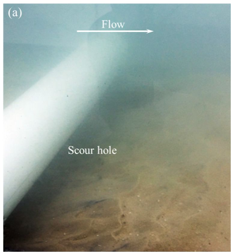
Sustainability 2020, 12, 3482 2 of 13
Sustainability 2020, 12, x FOR PEER REVIEW 2 of 14
three-dimensional
scour [7,8], the scour scour [7,8],
rate on the thescour rate on
spanwise the spanwise
direction [9,10],direction
and the[9,10], time andscalethe of time
scour scale
hole of
scour hole development
development [11–13]. [11–13].
Extendingthethe
Extending service
service lifetheofpipelines
life of the pipelines is of significant
is of significant importanceimportance
in improvingintheimprovingsustainability the
sustainability
of oil transportation.of oil transportation.
Properly designed Properly designedofprotection
protection underwater of underwater
pipelines improves pipelinesthe improves
safety,
the safety, sustainability,
sustainability, and economics andofeconomics of pipeline
pipeline operation. operation.
Protective Protective countermeasures
countermeasures against scour against under
scour under
pipelines havepipelines
become have the focusbecome the focus
of many of many
studies. At studies.
present, At such present,
methods suchcan methods
be generallycan be
generally
divided divided
into into two categories
two categories per their basic per their basic functionalities:
functionalities: (1) Stopping (1) Stopping
the onsetthe onset of
of scour and scour
(2)
and (2) stimulating the self-burial of pipelines. The former aims at
stimulating the self-burial of pipelines. The former aims at preventing the onset of scour by reducing preventing the onset of scour by
reducing
the seepagethehydraulic
seepage gradient
hydraulicacross gradient across the
the pipeline with pipeline
underwaterwith structures.
underwater Such structures.
techniques Such
techniques
include riprapsinclude ripraps
[14–16], [14–16],
flexible flexiblecovering
mattresses mattresses thecovering
pipelinethe pipeline
[17–19], [17–19],
fiber fiber mats
reinforced reinforced[20],
mats [20], and impermeable plates placed between the pipeline
and impermeable plates placed between the pipeline and the seabed [1,21]. In the latter category of and the seabed [1,21]. In the latter
category of
protection protection
methods, methods,
attempts wereattempts
made to were madescour
accelerate to accelerate scour hole
hole development development
beneath the pipeline beneathby
the pipeline
modifying thebycross-section
modifying the cross-section
profile profile The
of the pipeline. of the pipeline.
pipeline The then
could pipeline could the
complete then complete
self-burial
the self-burial
process soon afterprocessdeployment soon and afterthus deployment
get protected andunderthusthegetseabed.
protected Suchundermethods themainly
seabed. Such
include
methods
spoilers mainly
[22–24] andinclude
flexible spoilers [22–24] and
plates installed underflexible plates installed
the pipeline [25]. under the pipeline [25].
Traditionalripraps
Traditional ripraps are are
widelywidelyadopted adopted
in scour inprotection
scour protection in the deployment
in the deployment of previous
of previous underwater
underwater
pipelines. pipelines.
However, However, isthis
this technique technique is
less sustainable less sustainable
or environment friendly or environment
compared withfriendly novel
comparedmethods.
protection with novel protection
Ripraps covering methods.
pipelines Ripraps
requirecovering pipelines
a large amount require
of rock, andastone
largeminingamount canof
rock, and stone mining can cause substantial environmental problems.
cause substantial environmental problems. Recently, a lack of rocks with suitable size and properties Recently, a lack of rocks with
suitable
has been size
reported,and properties
along with has rising been reported,
costs in rock along
quarrying withand rising costs in rock
transportation [26].quarrying
In addition, and
transportation [26]. In addition, potential secondary scour may occur
potential secondary scour may occur near the edge of the ripraps covering the pipeline [27,28], threating near the edge of the ripraps
covering
the stability theof pipeline [27,28],and
both the riprap threating the stability
the pipeline. of both the
Thus, traditional riprapriprap and theispipeline.
protection unsustainable Thus,
traditional
in riprap protection
both construction and maintenance. is unsustainable in both also
Similar drawbacks construction
exist in some and other
maintenance.
aforementioned Similar
drawbackstechniques.
protection also exist in some other aforementioned protection techniques.
Inthis
In thispaper,
paper,aaGeotextile
GeotextileMattress
Mattresswith withFloating
FloatingPlate Plate(GMFP)
(GMFP)isisintroduced
introducedfor forpipeline
pipelinescour scour
protection(Figure
protection (Figure1). 1).AAGMFPGMFPisisaanovel noveldevice
devicedesigned
designedfor forscour
scourand anderosion
erosionprotection
protectionproposed
proposed
by[29].
by [29].ItItisiscomposed
composedofofa ageotextile
geotextile mattress
mattress andand a floating
a floating plate.
plate. The The geotextile
geotextile mattress
mattress consists
consists of
aofstring
a string of mattress
of mattress tubeswith
tubes filled filled with
sand, sand,cement,
gravel, gravel, orcement,
concrete, oroffering
concrete, offering
a sound a sound
foundation
foundation
for the GMFPfor the GMFP
structure. Thestructure.
floating plate The floating plate isplate
is an inflatable an inflatable
filled withplate air orfilled
other with
lightairmaterials
or other
lightpolymer
like materials like polymer
foam. foam.to
It is attached It the
is attached
geotextile to the geotextile
mattress withmattress
a series with a series
of strings on of the strings
bottom on
the bottom
edge. edge. the
In still water, In floating
still water, platethe risesfloating
straightplateup due rises straight up
to buoyancy. In adue to buoyancy.
unidirectional In a
current,
unidirectional
the floating platecurrent,leans tothe thefloating
leeside due platetoleans
the dragto the
force.leeside
Thus,dueit istoalso
theknown
drag force. Thus, it plate”.
as a “sloping is also
known
The as aintroduce
strings “sloping aplate”. The strings
gap between introduce
the bottom a gap
of the between
floating platetheand bottom of the floating
the mattress, which can plate and
serve
the
as mattress,for
a passage which
the bedcanload
serve andas thea passage for theflow.
near bottom bed Belts
load and the near
are added to bottom flow.and
the mattress Belts the are added
plate to
to the mattress and the plate to
improve the integral stability of the structure. improve the integral stability of the structure.
Figure 1. Sketch of the Geotextile Mattress with Floating plate (GMFP) [29].
Figure 1. Sketch of the Geotextile Mattress with Floating plate (GMFP) [29].
Sustainability 2020,12,
Sustainability2020, 12,3482
x FOR PEER REVIEW 33 of
of 13
14
Sustainability 2020, 12, x FOR PEER REVIEW 3 of 14
Figure 2 demonstrates the basic working mechanism of the GMFP in steady currents. When
Figure 22 demonstrates
Figure demonstratesthe thebasic working
basic working mechanism
mechanism of the
of GMFP
the GMFP in steady currents.
in steady When
currents.
the floating plate is deployed in a steady current, the approaching flow is separated into two
the floating
When plate is
the floating platedeployed
is deployedin a steady current,
in a steady the approaching
current, the approaching flow flow
is separated into into
is separated two
branches. The upper one is diverted to the top of the floating plate. The lower branch flows through
branches. The upper one is diverted to the top of the floating plate. The
two branches. The upper one is diverted to the top of the floating plate. The lower branch flows lower branch flows through
the gap between the floating plate and the mattress, reaching the leeside of the plate. The
the gap the
through between the floating
gap between plate and
the floating platetheand mattress, reaching
the mattress, the leeside
reaching of theofplate.
the leeside The
the plate.
interaction of these two flow branches on the downstream side of the floating plate forms two main
interaction
The of these
interaction twotwo
of these flow branches
flow branchesonon thethe
downstream
downstreamside sideofofthe
thefloating
floatingplate
plate forms two main main
vortex systems: The top vortices near the top edge of the floating plate and the bottom vortex close
vortex systems:
vortex systems: The Thetop
topvortices
vorticesnearnearthe
thetoptopedge
edgeofofthethe floating
floating plate
plate andand thethe bottom
bottom vortex
vortex close
close to
to the bed. The bottom vortex and the resulting low velocity zone create a long safe area on the
to the
the bed.bed.
TheThe
bottombottom
vortex vortex
and the andresulting
the resulting low velocity
low velocity zonea create
zone create long safe a long
area safe
on thearea on the
leeside of
leeside of the GMFP. The bed load passes the gap between the floating plate and the mattress with
leeside of the GMFP. The bed load passes the gap between the floating
the GMFP. The bed load passes the gap between the floating plate and the mattress with the bottom plate and the mattress with
the bottom flow, and is deposited in the safe area where the bottom velocity is low. When a GMFP
the bottom
flow, flow, and in
and is deposited is deposited
the safe area in where
the safe thearea where
bottom the bottom
velocity is low.velocity
When aisGMFP low. When a GMFP
is deployed so
is deployed so that the structure or bed to be protected is located within the safe area, the flow
is deployed
that so that
the structure the to
or bed structure or bed
be protected to be protected
is located within theissafe
located
area, within
the flowthe safe area,
velocity thethem
around flow
velocity around them is reduced. The sediment deposited near the structure in the safe area also
velocity
is reduced. around them is deposited
The sediment reduced. The nearsediment
the structure deposited neararea
in the safe thealso
structure
reduces inthe
thescour
safe potential.
area also
reduces the scour potential. Thus, scour is less likely to occur adjacent to the structure or bed. In
reduces
Thus, theisscour
scour potential.
less likely to occur Thus, scourtoisthe
adjacent less likely to
structure or occur
bed. Inadjacent
wave orto the structure
oscillating or bed. In
flow conditions,
wave or oscillating flow conditions, the bottom flow is bidirectional, and GMFPs are thus deployed
wave
the or oscillating
bottom flow conditions,
flow is bidirectional, andthe bottom
GMFPs areflow
thusisdeployed
bidirectional, andsides
on both GMFPs arestructure
of the thus deployed
to be
on both sides of the structure to be protected so that the structure is always located in the safe area
on both sides
protected so that of the structure is always located in the safe area of one of the GMFPs (Figure 3). area
to be protected so that the structure is always located in the safe
of one of the GMFPs (Figure 3).
of one of the GMFPs (Figure 3).
Figure 2. Basic
Basic working mechanism
mechanism of the
the GMFP.
Figure 2. Basic working
Figure 2. working mechanism of
of the GMFP.
GMFP.
Figure 3. Sketch of GMFPs protecting a structure in wave conditions.
Figure 3. Sketch of GMFPs protecting a structure in wave conditions.
Figure 3. Sketch of GMFPs protecting a structure in wave conditions.
The GMFP shows sustainability in both deployment and maintenance phases. On one hand,
The GMFP
The GMFP showsshows sustainability
sustainability inin both
both deployment
deployment and
and maintenance
maintenance phases.
phases. On one hand,
various materials can be used to fill the mattress tubes of the geotextile mattress (Figure 1). Besides
various materials can be used to fill the mattress tubes of the geotextile
various materials can be used to fill the mattress tubes of the geotextile mattress mattress (Figure (Figure
1). Besides
1).
the traditional materials mentioned above, local dredging materials like silt and clay can also be
the traditional
Besides materials
the traditional mentioned
materials above, local
mentioned above,dredging materials
local dredging like silt like
materials and silt
clayand
canclay
alsocan
be
used to fill the mattress tubes, which are easily accessible in port and waterway maintenance.
usedbetoused
also fill to
thefillmattress tubes,
the mattress which
tubes, are are
which easily accessible
easily in inport
accessible portand
andwaterway
waterway maintenance.
Inappropriate disposal of dredged soil can bring pollution to local marine environment. Thus, the
Inappropriate disposal of
Inappropriate of dredged
dredged soil
soilcan
canbring
bringpollution
pollutiontotolocal marine
local marine environment.
environment. Thus, the
Thus,
deployment of GMFP structures is more sustainable than that of ripraps, which demands large
deployment of GMFP structures is more sustainable than that of ripraps, which demands large
amounts of nonrenewable rocks. On the other hand, the GMFP also shows sustainability in
amounts of nonrenewable rocks. On the other hand, the GMFP also shows sustainability in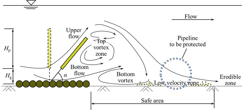
Sustainability 2020, 12, 3482                                                                         4 of 13

the deployment of GMFP structures is more sustainable than that of ripraps, which demands
large amounts of nonrenewable rocks. On the other hand, the GMFP also shows sustainability in
maintenance. After. the deployment of the GMFP, dynamic equilibrium is soon reached and maintained
in the sediment transportation near the protected seabed. As the GMFP is capable of trapping bed load
and depositing the sediment in the safe area on its leeside [26], sand dunes can form near the structure
to be protected in normal times. When the sediment transportation capacity of the approaching flow
increases dramatically in extreme conditions (i.e., flood and tropical cyclones), the floating plate inclines
to the bed, making it easier to survive the disaster. Sand dunes deposited near the protected structure
can be scoured, but the structure will still remain intact. After. the disaster, the GMFP structure may
need some maintenance, but the maintenance does not consume nonrenewable materials like rocks.
Sediment trapping can start automatically soon after the hydraulic conditions recovers. The dynamic
equilibrium of the seabed sediment transportation in the protected area enables a sustainable protection
of the bed and the structure from potential scour.
      Studies have been conducted on the GMFP and similar structures. Li and Yu [30] investigated
the flow structure on the leeside of a suspended flexible curtain with a simplified Particle Image
Velocimetry (PIV) system. An empirical formula was established for the variation of the lee wake
vortex dimensions with the curtain height. Xie et al. [26] performed a series of flume experiments on
the geotextile mattress with sloping curtain in currents under live bed conditions. Local bed erosion was
seized after the structure was deployed. Sediment trapping was detected on both sides of the structure.
Xie et al. [31] extended the study of Xie et al. [26] and applied the geotextile mattress with sloping
curtain to scour protection under a partially buried pipeline in currents. Visualization test results
showed that the structure is capable of slowing down and even reversing the seepage flow beneath
the pipeline. Wang et al. [32] investigated the hydrodynamic properties of a sloping curtain. A series
of empirical formulae were proposed to estimate the variation of the properties, including the sloping
angles, the length of the bottom vortex, and the forces on the structure. Xie et al. [29] improved
the flexible protection structure presented by Xie et al. [26], and proposed the GMFP. The seepage
stability of the GMFP structure was analyzed in detail based on the experiment results and the potential
risk of seepage failure in practical engineering was also discussed.
      Both the GMFP studied in this structure and previously proposed structures [26,30–33] are
different novel scour control measures, and are appropriate for different situations. Compared with
some of these structures, the GMFP requires less effort and cost in deployment and maintenance [29].
It should be noted that the GMFP is different from the geotextile mattress with sloping curtain studied
in Xie et al. [26,31]. Such differences include the structure of the sand-pass openings, and the flexibility
of the floating plate (curtain), to name a few. Structural distinctions in these two devices can result in
a different flow pattern downstream and cause further variation in protection of underwater structures.
Previous achievements are not necessarily applicable to the GMFP. Thus, it is necessary to validate
the protection effects of the GMFP and investigate the influence on the protection.
      As mentioned above, the dominant cause of the onset of scour below the pipelines is the excessive
seepage hydraulic gradient in the soil. If a pipeline is located in the safe area on the leeside of the GMFP,
the approaching flow velocity could be remarkably reduced. Thus, the seepage hydraulic gradient
under the pipeline can be decreased and the onset of scour is less likely to occur.
      In this research, the GMFP was introduced as a protective measure against scour under the pipelines
in steady currents (Figure 2). Pore pressure beneath the pipeline was measured to calculate the seepage
hydraulic gradient. A series of tests were designed to investigate the protective effects of the GMFP on
a partially buried pipeline. The protective effects of the GMFP were verified and the effects of the GMFP
design parameters were evaluated. The results of this study are helpful to improve the understanding
of the scour protection effects of the GMFP and accelerate the practical application of the GMFP,
which can improve the sustainability of pipeline operation.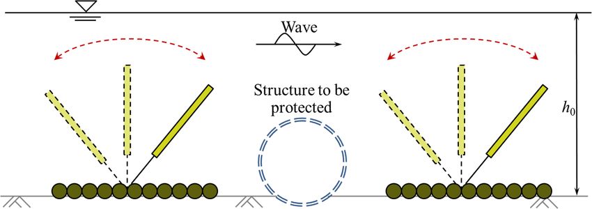
Sustainability 2020, 12, 3482                                                                                             5 of 13
Sustainability 2020, 12, x FOR PEER REVIEW                                                                                5 of 14

2.
2. Experiment
   Experiment Setup
              Setup

2.1.
2.1. Experimental
     Experimental Apparatus
                  Apparatus
     The   experimentswere
      The experiments       wereconducted
                                     conducted      in in
                                                        thethe Laboratory
                                                             Laboratory        of Hydraulic
                                                                           of Hydraulic         and Harbor
                                                                                           and Harbor           Engineering
                                                                                                         Engineering            at
                                                                                                                         at Tongji
Tongji  University.
University.   Figure 4Figure
                          shows4the   showsside theviewside    view
                                                          of the  flumeof the
                                                                           andflume     and the experimental
                                                                                the experimental                     setup. The
                                                                                                       setup. The glass-sided
glass-sided
flume is 50 flume
              m long,  is 0.8
                          50 mm long,
                                   wide 0.8   andm1.2 wide    and 1.2
                                                         m deep.     Two m metal
                                                                            deep. Two
                                                                                    fencesmetal    fences are
                                                                                            are installed    at installed
                                                                                                                 the flumeatinlet
                                                                                                                               the
flume  inlet  and   outlet  to  stabilize       the  current   in the   flume.   The  flow   in the  flume
and outlet to stabilize the current in the flume. The flow in the flume is generated by a pumping system,    is generated     by a
pumping     system,of
which is capable       which   is capable
                         producing       a steady of producing
                                                        current ata1.0steady   current
                                                                          m/s with   0.4 at
                                                                                         m 1.0
                                                                                            flow m/s  with A
                                                                                                    depth.  0.4sediment
                                                                                                                  m flow depth.
                                                                                                                            recess
A  sediment    recess   with   a  length       of 2.7  m   and  a  depth    of 1.0 m  is located
with a length of 2.7 m and a depth of 1.0 m is located 20 m downstream of the entrance of the flume.20  m  downstream       of the
entrance
The bottom of the   flume.
               of the   flumeTheand bottom        of the and
                                        the recess,        flume
                                                               all and
                                                                    sidethe   recess,
                                                                          walls  of theand  all side
                                                                                          recess  are walls
                                                                                                       made of of the  recess are
                                                                                                                   impermeable
made   of impermeable
concrete.   Uniform sand    concrete.
                               with a Uniform
                                           median grain  sand size        = 0.16 mm
                                                               withda50median      grainand
                                                                                          sizegeometric
                                                                                                d50 = 0.16 standard
                                                                                                           mm and geometric
                                                                                                                        deviation
σg = (d84 /d16 ) = 1.4 was used in this research. The sediment was selected based on previous studies
standard        1/2
           deviation    σ g = (d 84 / d 16 ) 1/2 = 1.4 was used in this research. The sediment was selected based

on
on previous
    scour understudies   on scour under pipelines.
                    pipelines.

                                  Figure 4.
                                  Figure    Experimentsetup
                                         4. Experiment setup (side
                                                              (side view,
                                                                    view, not
                                                                          not to
                                                                              to scale).
                                                                                 scale).

     A plastic pipeline which was 0.8 m long and 0.11 m in diameter was chosen as the model pipeline.
     A plastic pipeline which was 0.8 m long and 0.11 m in diameter was chosen as the model
The pipeline was partially buried with the embedment depth e = 0.5 cm (Figure 4). Both ends of
pipeline. The pipeline was partially buried with the embedment depth e = 0.5 cm (Figure 4). Both
the pipeline were fixed to avoid pipeline movement during the experiments. A series of GMFP models
ends of the pipeline were fixed to avoid pipeline movement during the experiments. A series of
were used in the experiment (Figure 5). The width of the GMFP models was 0.8 m, the same as the flume
GMFP models were used in the experiment (Figure 5). The width of the GMFP models was 0.8 m, the
width. The height of the floating plate H varied from 0.08 m to 0.16 m. The length of the GMFP
same as the flume width. The height of thepfloating plate Hp varied from 0.08 m to 0.16 m. The length
mattress was 0.25 m. The GMFP model was placed at 1.0 m to the upstream end of the sediment
of the GMFP mattress was 0.25 m. The GMFP model was placed at 1.0 m to the upstream end of the
recess. The distance between the GMFP and the pipeline was 0.8 m, which was selected according to
sediment recess. The distance between the GMFP and the pipeline was 0.8 m, which was selected
the results of Xie et al. [26] to achieve the optimum protection effects. An Acoustic Doppler Velocimeter
according to the results of Xie et al. [26] to achieve the optimum protection effects. An Acoustic
(ADV) was placed 3.0 m upstream to the sediment recess to monitor the averaged approach velocity.
Doppler Velocimeter (ADV) was placed 3.0 m upstream to the sediment recess to monitor the
     Two digital pore pressure transducers (Chengdu Test Electronic Information, Chengdu, China)
averaged approach velocity.
were used in this study. The full range of the pressure sensors is 10 kPa, which is capable of
capturing the variations in the pressure difference on two sides of the pipeline. The sampling rate of
the pressure sensors was 100 Hz. The onset of scour was reported to start on the downstream side
of the pipeline [2,34] and numerical simulations on the seepage field under the pipeline showed that
the upward seepage hydraulic gradient reaches the maximum value at the intersection of the pipeline
surface and the downstream bed [3,35]. Thus, the seepage hydraulic gradient on the downstream side
under the pipeline was the focus of this study. The average seepage hydraulic gradient was calculated
based on the pressure sensor readings (Figure 6). Sensor A was installed at the bottom of the pipeline
on the vertical axis and Sensor B was installed close to the bed surface. The arc length between Sensors
A and B was 20 mm. Thus the averaged seepage hydraulic gradient between points A and B ∂(p/γ)/∂s
was calculated by (Figure 6):
                                               ∂ p
                                                    !
                                                        pA − pB
                                                      =    _ ,                                        (1)
                                               ∂s γ
                                                         γAB
Sustainability 2020, 12, 3482 6 of 13
Figure 5. A GMFP model in the experiment.
where γ is the specific weight of water; s is the distance along the perimeter of the pipeline; pA and pB
_
Two digital pore pressure transducers (Chengdu Test Electronic Information, Chengdu, China)
are pore pressure at Sensors A and B, respectively, and AB is the arc length between Sensors A and B,
were used in this study. The full range of the pressure sensors is 10 kPa, which is capable of
which is 20 mm. This equation is derived from the definition in Sumer et al. [2].
Sustainability
capturing the 2020,variations
12, x FOR PEER REVIEW
in the 6 of of
pressure difference on two sides of the pipeline. The sampling rate 14
the pressure sensors was 100 Hz. The onset of scour was reported to start on the downstream side of
the pipeline [2,34] and numerical simulations on the seepage field under the pipeline showed that
the upward seepage hydraulic gradient reaches the maximum value at the intersection of the
pipeline surface and the downstream bed [3,35]. Thus, the seepage hydraulic gradient on the
downstream side under the pipeline was the focus of this study. The average seepage hydraulic
gradient was calculated based on the pressure sensor readings (Figure 6). Sensor A was installed at
the bottom of the pipeline on the vertical axis and Sensor B was installed close to the bed surface. The
arc length between Sensors A and B was 20 mm. Thus the averaged seepage hydraulic gradient
between points A and B ∂(p/γ)/∂s was calculated by (Figure 6):
∂ p pA − pB
= , (1)
∂s γ γ AB
where γ is the specific weight of water; s is the distance along the perimeter of the pipeline; pA and
pB are pore pressure at Sensors A and B, respectively, and AB is the arc length between Sensors A
and B, which is 20 mm. This equation
Figure 5.isAderived frominthe
GMFP model thedefinition in Sumer et al. [2].
experiment.
Figure 5. A GMFP model in the experiment.
Two digital pore pressure transducers (Chengdu Test Electronic Information, Chengdu, China)
were used in this study. The full range of the pressure sensors is 10 kPa, which is capable of
capturing the variations in the pressure difference on two sides of the pipeline. The sampling rate of
the pressure sensors was 100 Hz. The onset of scour was reported to start on the downstream side of
the pipeline [2,34] and numerical simulations on the seepage field under the pipeline showed that
the upward seepage hydraulic gradient reaches the maximum value at the intersection of the
pipeline surface and the downstream bed [3,35]. Thus, the seepage hydraulic gradient on the
downstream side under the pipeline was the focus of this study. The average seepage hydraulic
gradient was calculated based on the pressure sensor readings (Figure 6). Sensor A was installed at
the bottom of the pipeline on the vertical axis and Sensor B was installed close to the bed surface. The
arc length between Sensors A and B was 20 mm. Thus the averaged seepage hydraulic gradient
between points A and B ∂(p/γ)/∂s was calculated by (Figure 6):
Figure 6.
Figure ppressure
6.∂Pore
Pore pA −sensor
pressure pB setup.
sensor setup.
= , (1)
The pressure measurements were ∂s γbefore
started γ
the AB
current was generated and lasted until at least
The pressure measurements were started before the current was generated and lasted until at
3least
min3after
min the flow
after thevelocity
flow becamebecame
velocity stable when
stableno scourno
when occurred.
scourthe Thus, theThus,
occurred. variations in the readings
where γ is the specific weight of water; s is the distance along perimeter of the
the variations
pipeline; pin the
A and
were completely recorded. The total duration of a test case was about 8 to 10 min for the cases where
B are did
pscour porenot
pressure at Sensors A where
and B, scour
respectively,
AB iswere
andreadings the arc length until
between Sensors A
occur. For the cases did occur, recorded the scour hole
and B, which is 20 mm. This equation
extended to the full length of the pipeline.is derived from the definition in Sumer et al. [2].
2.2. Experimental Cases
The design parameters of a GMFP include the plate height Hp , the sloping angle α, and the opening
ratio δ, which is defined as:
Hg
δ = , (2)
Hp + Hg
where Hg is the height of the gap between the floating plate and the geotextile mattress, and Hp
is the height of the floating plate (Figure 2). In this study, a total of 15 cases were designed for
the experiment. The flow depth was set at h0 = 0.4 m in all cases. The average velocity was constant
at 0.4 m/s. The cases were divided into four groups. Group A was set as a control group; no GMFP was
Figure 6. Pore pressure sensor setup.Sustainability 2020, 12, 3482 7 of 13
installed and the pipeline was unprotected. Groups B, C, and D, respectively, focused on the effects of
the sloping angle α, the opening ratio δ, and the plate height Hp , respectively. In each group, only one
parameter was changed while the others were kept constant. Further details of the cases are listed
in Table 1. The aim of the present experiment is to validate the protection capability of the GMFP
and reveal the qualitative variation mode of the protective effects with the GMFP design parameters.
Thus, the scaling was considered less important. More comprehensive investigations will be presented
in future papers with scaling considered and other parameters included.
Table 1. Experiment cases.
Group Case Sloping Angle α (◦ ) Opening Ratio δ Plate Height H p (m)
A A1 Control test, without GMFP
B B1 35 0.231 0.10
B2 40 0.231 0.10
B3 45 0.231 0.10
B4 50 0.231 0.10
B5 55 0.231 0.10
B6 60 0.231 0.10
C C1 50 0.167 0.10
B4 50 0.231 0.10
C3 50 0.286 0.10
C4 50 0.333 0.10
D D1 50 0.231 0.08
D2 50 0.231 0.10
D3 50 0.231 0.12
D4 50 0.231 0.16
3. Experiment Results
3.1. Verification of GMFP Protection Effects
Two additional, independent test cases were conducted to observe the protective effects of the GMFP.
The observation test was based on Case A1, where the GMFP was not installed and the pipeline was
unprotected, and Case B4, where a GMFP was deployed upstream to the pipeline. The steady current
was maintained at 0.4 m/s for 30 min. The other experimental parameters were all kept unchanged in
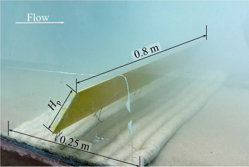
Table 1. Figure 7 shows the sand bed adjacent to the pipeline without a GMFP (Figure 7a) and with
a GMFP (Figure 7b) after the test. This figure shows that after 30 min of flow, the sediment below
the pipeline without a GMFP suffered serious scouring, while the bed with a GMFP installed remained
almost intact. Therefore, we demonstrate that the GMFP is capable of protecting a pipeline from scour
in steady currents.
Table 2 shows the experimental results of Cases A1 (control case) and B4. It shows that while
serious scour appeared in Case A1, no scour occurred in Case B4 (Figure 7). The averaged seepage
hydraulic gradient across the pipeline was reduced by about 65% after the GMFP is installed (Case B4
compared with Case A1). For all of the tested cases, scour underneath the pipeline was only observed
in Case A1, the control case. The GMFP is therefore proven to be capable of decreasing the excessive
seepage hydraulic gradient under the pipeline in currents, which is regarded to be a major cause of
the onset of scour of pipeline.
Table 2. Experiment results of Cases A1 and B4.
Case With GMFP Scour Depth (cm) Averaged Seepage Hydraulic Gradient ∂(p/γ)/∂s
A1 No 6.5 0.643
B4 Yes 0 0.225Sustainability 2020, 12, x FOR PEER REVIEW 8 of 14
GMFP installed
Sustainability 2020, 12,remained
3482 almost intact. Therefore, we demonstrate that the GMFP is capable
8 of of
13
protecting a pipeline from scour in steady currents.
Figure 7. Sand
Figure 7. Sand bed
bedtransformation
transformationunder
underthe
the pipeline
pipeline after
after 30 30
minmin flow:
flow: (a) Without
(a) Without a GMFP;
a GMFP; (b)
(b) with
with a GMFP.
a GMFP.
Table of
3.2. Effects 2 shows the experimental
GMFP Sloping Angle on theresults of Cases
Averaged A1Hydraulic
Seepage (control Gradient
case) and(Test
B4. Group
It shows
B) that while
serious scour appeared in Case A1, no scour occurred in Case B4 (Figure 7). The averaged seepage
Figure 8 shows the variation of average seepage hydraulic gradient ∂(p/γ)/∂s with the sloping
hydraulic gradient across the pipeline was reduced by about 65% after the GMFP is installed (Case
angle α varying from 35◦ to 60◦ . The other two variables were kept constant, i.e., opening ratio δ = 0.231
B4 compared with Case A1). For all of the tested cases, scour underneath the pipeline was only
and plate height Hp = 0.10 m. The sloping angle was normalized as sinα. In general, the average
observed in Case A1, the control case. The GMFP is therefore proven to be capable of decreasing the
seepage hydraulic gradient decreases with an increase of sloping angle when sinα is between 0.64
excessive seepage hydraulic gradient under the pipeline in currents, which is regarded to be a
and 0.77, after a modest increase when sinα increases from 0.57 to 0.64. The average hydraulic gradient
major cause of the onset of scour of pipeline.
reached the minimum value for the tested range of parameters at sinα = 0.77, and then rose when
sinα > 0.82. The nadir point in this curve can be regarded as an optimum sloping angle of the GMFP in
Table 2. Experiment results of Cases A1 and B4.
the present configuration. The variation of the seepage hydraulic gradient with the sloping angle can
be partiallyCase attributed Scourchange
Depth and Averaged Seepage of
Hydraulic Gradient
WithtoGMFP
the intensity the deformation the bottom vortex (Figure 2),
Sustainability
which will be2020, 12, x FOR PEER
discussed REVIEW
in detail (cm) section.
in a later ∂(p/γ)/∂s 9 of 14
A1 No 6.5 0.643
B4 Yes 0 0.225
3.2. Effects of GMFP Sloping Angle on the Averaged Seepage Hydraulic Gradient (Test Group B)
Figure 8 shows the variation of average seepage hydraulic gradient ∂(p/γ)/∂s with the sloping
angle α varying from 35° to 60°. The other two variables were kept constant, i.e., opening ratio δ =
0.231 and plate height Hp = 0.10 m. The sloping angle was normalized as sinα. In general, the
average seepage hydraulic gradient decreases with an increase of sloping angle when sinα is
between 0.64 and 0.77, after a modest increase when sinα increases from 0.57 to 0.64. The average
hydraulic gradient reached the minimum value for the tested range of parameters at sinα = 0.77, and
then rose when sinα > 0.82. The nadir point in this curve can be regarded as an optimum sloping
angle of the GMFP Figurein
Figure 8. the present
8. Variation
Variation of configuration.
ofaveraged
averaged seepage The variation
seepagehydraulic
hydraulic of with
gradient
gradient the
withseepage
sloping hydraulic gradient
slopingangle.
angle.
with the sloping angle can be partially attributed to the intensity change and the deformation of the
3.3. Effects
bottom of GMFP
vortex Opening
(Figure Ratiowill
2), which on the discussed
Averaged Seepage Hydraulic
in a laterGradient
section.(Test Group C)
3.3. Effects of GMFP Opening Ratio onbe in detail
the Averaged Seepage Hydraulic Gradient (Test Group C)
Figure 9 shows the variation of the average seepage hydraulic gradient ∂(p/γ)/∂s with the opening
Figure 9 shows the variation of the average seepage hydraulic gradient ∂(p/γ)/∂s with the
ratio δ varying from 0.167 to 0.333. The other two variables were kept constant, i.e., sloping angle
opening ratio δ varying from 0.167 to 0.333. The other two variables were kept constant, i.e., sloping
α = 50◦ and plate height Hp = 0.10 m. The average seepage hydraulic gradient drops slightly when
angle α = 50° and plate height Hp = 0.10 m. The average seepage hydraulic gradient drops slightly
the opening ratio δ increases from 0.167 to 0.231, hitting a nadir at δ = 0.231, and then increases with
when the opening ratio δ increases from 0.167 to 0.231, hitting a nadir at δ = 0.231, and then increases
the increase of the opening rate when δ > 0.231. The seepage hydraulic gradient ∂(p/γ)/∂s increases by
with the increase of the opening rate when δ > 0.231. The seepage hydraulic gradient ∂(p/γ)/∂s
increases by about 40% when δ increases from 0.231 to 0.333. More detailed analysis on the variation
pattern is given in a later section.3.3. Effects of GMFP Opening Ratio on the Averaged Seepage Hydraulic Gradient (Test Group C)
Figure 9 shows the variation of the average seepage hydraulic gradient ∂(p/γ)/∂s with the
opening ratio δ varying from 0.167 to 0.333. The other two variables were kept constant, i.e., sloping
angle α = 50° and plate height Hp = 0.10 m. The average seepage hydraulic gradient drops slightly
Sustainability 2020, 12, 3482 9 of 13
when the opening ratio δ increases from 0.167 to 0.231, hitting a nadir at δ = 0.231, and then increases
with the increase of the opening rate when δ > 0.231. The seepage hydraulic gradient ∂(p/γ)/∂s
about 40%bywhen
increases aboutδ 40%increases
whenfrom 0.231 to
δ increases 0.333.
from More
0.231 detailed
to 0.333. analysis
More onanalysis
detailed the variation
on thepattern is
variation
given in a later section.
pattern is given in a later section.
Figure
Figure 9. Variation of
9. Variation of averaged
averaged seepage
seepage hydraulic
hydraulic gradient
gradient with
with opening
opening ratio.
ratio.
3.4. Effects of GMFP Plate Height on the Averaged Seepage Hydraulic Gradient (Test Group D)
3.4. Effects of GMFP Plate Height on the Averaged Seepage Hydraulic Gradient (Test Group D)
Figure 10 shows the variation of the average seepage hydraulic gradient ∂(p/γ)/∂s with the GMFP
Figure 10 shows the variation of the average seepage hydraulic gradient ∂(p/γ)/∂s with the
plate height Hp varying from 0.08 m to 0.16 m. The other two variables were kept constant, i.e., sloping
GMFP plate height Hp varying from 0.08 m to 0.16 m. The other two variables were kept constant,
angle α = 50◦ and opening ratio δ = 0.231. The plate height was normalized as the relative plate height
i.e., sloping angle α = 50° and opening ratio δ = 0.231. The plate height was normalized as the
Hp /h0 , where h0 = water depth. In Figure 10, the average seepage hydraulic gradient shows a gradual
relative plate height Hp/h0, where h0 = water depth. In Figure 10, the average seepage hydraulic
decrease with increased plate height, except for a fluctuation at Hp /h0 = 0.3 (Hp = 0.12 m). The drop of
gradient shows a gradual decrease with increased plate height, except for a fluctuation at Hp/h0 = 0.3
the seepage hydraulic gradient with increasing plate height may also be associated with the increase of
(Hp = 0.12 m). The drop of the seepage hydraulic gradient with increasing plate height may also be
the obstruction height. A more detailed discussion of the relationship between the obstruction height
associated with the increase of the obstruction height. A more detailed discussion of the
and the average
Sustainability seepage
2020, 12, hydraulic
x FOR PEER REVIEWgradient will be presented in the next section. 10 of 14
relationship between the obstruction height and the average seepage hydraulic gradient will be
presented in the next section.
Figure 10. Variation of averaged seepage hydraulic gradient with
with relative
relative plate
plate height.
height.
4. Discussion
4. Discussion
4.1. Effects of GMFP Obstruction Height on the Hydraulic Gradient
4.1. Effects of GMFP Obstruction Height on the Hydraulic Gradient
It has been proved that the dimensions of the bottom vortex downstream to a similar structure are
It has been proved that the dimensions of the bottom vortex downstream to a similar structure
a function of the structure blockage [30], and the protective effect is closely associated with the length
are a function of the structure blockage [30], and the protective effect is closely associated with the
of the bottom vortex (Figure 2). It is thus necessary to analyze the variation of the seepage hydraulic
length of the bottom vortex (Figure 2). It is thus necessary to analyze the variation of the seepage
gradient with the blockage of the plate to further explain the variation of the hydraulic gradient with
hydraulic gradient with the blockage of the plate to further explain the variation of the hydraulic
the sloping angle and the plate height in Figures 8 and 10.
gradient with the sloping angle and the plate height in Figures 8 and 10.
The variation of the averaged seepage hydraulic gradient ∂(p / γ)/∂s with the sloping angle
The variation of the averaged seepage hydraulic gradient ∂(p / γ)/∂s with the sloping angle and
and the plate height is plotted as the relationship between the hydraulic gradient and the obstruction
the plate height is plotted as the relationship between the hydraulic gradient and the obstruction
height of the floating plate Hp sinα (Figure 11). The result of the control test is also included,
height of the floating plate Hpsinα (Figure 11). The result of the control test is also included, where
where the obstruction height is zero. The data in Figure 9 is not included, as the tests in Figure 9 focus
the obstruction height is zero. The data in Figure 9 is not included, as the tests in Figure 9 focus on
on the height of the gap, which is independent from the obstruction height. Figure 11 demonstrates
the height of the gap, which is independent from the obstruction height. Figure 11 demonstrates
that the averaged seepage hydraulic gradient under the pipeline decreases with increasing
obstruction height in a nonlinear trend. The descent rate gradually drops with the rise of the
obstruction height.gradient with the sloping angle and the plate height in Figures 8 and 10.
The variation of the averaged seepage hydraulic gradient ∂(p / γ)/∂s with the sloping angle and
the plate height is plotted as the relationship between the hydraulic gradient and the obstruction
height of the floating plate Hpsinα (Figure 11). The result of the control test is also included, where
the obstruction
Sustainability height
2020, 12, 3482 is zero. The data in Figure 9 is not included, as the tests in Figure 9 focus
10 of on
13
the height of the gap, which is independent from the obstruction height. Figure 11 demonstrates
that the averaged seepage hydraulic gradient under the pipeline decreases with increasing
that the averaged
obstruction height seepage hydraulic gradient
in a nonlinear under
trend. The the pipeline
descent decreasesdrops
rate gradually with increasing
with the obstruction
rise of the
height in a nonlinear
obstruction height. trend. The descent rate gradually drops with the rise of the obstruction height.
Figure 11. Variation
Figure 11. Variationofof
averaged seepage
averaged hydraulic
seepage gradient
hydraulic with with
gradient the normalized plate obstruction
the normalized height.
plate obstruction
height.
In Figure 11, the results of Xie et al. [31] are also plotted. Xie et al. [31] visualized the protection
effectsInofFigure
a similar
11,scour controlofmethod
the results called
Xie et al. [31]geotextile mattressXie
are also plotted. with
et sloping
al. [31] curtain in steady
visualized currents.
the protection
The variation
effects of thescour
of a similar hydraulic gradient
control method with the geotextile
called obstructionmattress
height of thesloping
with previous study in
curtain [31] also
steady
shows a gradual decrease with the decrease rate slowing down. The minor difference
currents. The variation of the hydraulic gradient with the obstruction height of the previous study in the variation
pattern
[31] also of shows
the hydraulic gradient
a gradual in these
decrease withtwothestudies may
decrease be slowing
rate attributed to twoThe
down. factors.
minor The first factor
difference in
is the
the structural
variation differences
pattern between the
of the hydraulic deviceinin
gradient Xie two
these et al.studies
[31] and
may thebeone studiedtointwo
attributed thisfactors.
study,
which
The firstcould result
factor instructural
is the differences in local flow
differences patterns
between and thus
the device protection
in Xie effects.
et al. [31] and theTheonevariation
studied
pattern of the hydraulic gradient with the obstruction height can also be different. Another
in this study, which could result in differences in local flow patterns and thus protection effects. factor may
be
Thethat the testpattern
variation conditions in this
of the study gradient
hydraulic are significantly
with thedifferent fromheight
obstruction the earlier study,
can also beincluding
different.
the differences in the experimental setup, and the hydrodynamic conditions.
Another factor may be that the test conditions in this study are significantly different from the
A possible explanation for the variation of the hydraulic gradient with the obstruction height
is hereby presented. With the increase of the obstruction height, the bottom vortex on the leeside
of the GMFP (Figure 2) tends to be enhanced. Li and Yu [30] found that the bottom vortex extends
downstream with the rise of the obstruction height. With the extension of the bottom vortex, the low
velocity zone and the safe area would stretch as well. When the distance between the pipeline
and the GMFP is constant, the pipeline gradually approaches the bottom vortex, and moves further
into the safe area due to the extension of the bottom vortex and the safe area. The influence on
the pipeline intensifies. The near bottom flow velocity drops with the extension of the bottom vortex.
As a result, the flow adjacent to the pipeline may slow down and the seepage hydraulic gradient
beneath the pipeline can decrease.
Additionally, it should be noted that not all of the data points of this study in Figure 11
collapse on a single curve, indicating that additional mechanisms may also affect the variation of
the hydraulic gradient except for the elementary mechanism above. Further investigation is necessary
on the interrelationship among the design parameters of the GMFP, the distance between the GMFP
and the pipeline, and the flow conditions. Such investigations will be helpful to better understand
the interaction mechanism between the pipeline and the GMFP structure in various conditions.
4.2. Effects of the Opening Ratio on the Hydraulic Gradient
In Figure 9, the hydraulic gradient drops slightly with the opening ratio when δ < 0.231.
The hydraulic gradient hits a nadir at δ = 0.231, and then increases with the increase of the opening
rate when δ > 0.231. This variation can be explained as follows.
When the opening ratio is zero, the gap between the floating plate and the mattress does not exist,
and the bottom flow is not capable of passing the plate from the bottom. In this occasion, only one
vortex exists on the leeside of the pipeline [30]. When the opening ratio δ increases from 0 to 0.231,
the gap appears and widens. The bottom flow appears in the gap (Figure 2), which significantlySustainability 2020, 12, 3482 11 of 13
changes the flow pattern on the leeside of the GMFP. The top vortices appear; the bottom vortex can
gradually move downstream and deform, and the intensity of the bottom vortex is slightly reduced [30].
As the bottom vortex moves to the leeside, the impact of the bottom vortex on the pipeline intensifies,
despite the drop in the intensity of the bottom vortex. Thus, the hydraulic gradient across the pipeline
decreases with the rising opening ratio when the opening ratio is small. The nadir point on this curve
indicates an optimum value of the opening ratio, where the protection effect of the GMFP reaches
an optimized value under the specified configuration of other parameters. In practical engineering
projects, the opening ratio is optimized on the basis of flume experiments.
With a continuous increase of the opening ratio, the variation trend of the flow pattern on
the leeside of the GMFP becomes different. The bottom flow through the gap keeps intensifying with
the rising gap height. The intensity of the bottom vortex continues to descend [30], probably due to
the disturbance of the intensifying bottom flow. The flow velocity in the low velocity zone increases,
and the protective effects fade. It is also reported that the bottom vortex coverage of narrows when
the opening ratio increases [30]. Thus, the flow around the pipeline tends to strengthen the average
seepage hydraulic gradient rises. If the opening ratio continues to rise, the protective effect of the GMFP
may even completely vanish as the bottom vortex could be overwhelmed by intense flow through
the opening gap.
5. Conclusions
In this study, a series of physical tests was designed and conducted to verify the protective
effects of the GMFP on a pipeline in steady currents. The effects of the GMFP design parameters on
the averaged seepage hydraulic gradient under the pipeline are also discussed. These achievements can
push forward the practical application of the GMFP, which will improve the sustainability of pipeline
deployment and operation by extending the service life of the underwater pipelines. The following
conclusions can be drawn based on the results above.
1. A GMFP structure installed on the upstream side of the pipeline is capable of protecting the pipeline
from scour in steady currents effectively. For all cases performed in this study, scour beneath
the pipeline is successfully prevented when a GMFP is installed. The seepage hydraulic gradient
in the soil under the pipeline is significantly reduced after a GMFP structure is deployed.
2. The average seepage hydraulic gradient under the pipeline decreases with an increase in
the sloping angle α when 0.64 < sinα < 0.77. After. hitting a nadir at sinα = 0.77, the hydraulic
gradient increases with the sloping angle when sinα > 0.82.
3. The average seepage hydraulic gradient under the pipeline drops with the increase of the opening
ratio δ when 0.167 < δ < 0.231, and then increases when δ > 0.231. The rise of hydraulic gradient
with the opening ratio can be associated with the drop in the intensity of the bottom vortex.
4. The average seepage hydraulic gradient under the pipeline shows a gradual decrease with
increased plate height Hp , except for a fluctuation at Hp = 0.12 m.
5. The average seepage hydraulic gradient has an approximate negative correlation with
the obstruction area of the floating plate (Hp sinα/h0 ), which can be partially attributed
to the extension of the bottom vortex on the leeside of the GMFP with the increase of
the obstruction area.
Author Contributions: Conceptualization, Y.Z., L.X., and T.-C.S.; funding acquisition, Y.Z. and L.X.; investigation,
Y.Z., L.X., and T.-C.S.; methodology, Y.Z., L.X., and T.-C.S.; resources, Y.Z. and L.X.; supervision, L.X.; visualization,
Y.Z. and L.X.; writing—original draft, Y.Z.; writing—review and editing, Y.Z., L.X., and T.-C.S. All authors have
read and agreed to the published version of the manuscript.
Funding: This research was funded by the National Natural Science Foundation of China, grant numbers 11172213
and 51479137, and the China Scholarship Council, grant number 201806260166.
Conflicts of Interest: The authors declare no conflict of interest. The funders had no role in the design of the study;
in the collection, analyses, or interpretation of data; in the writing of the manuscript, or in the decision to publish
the results.Sustainability 2020, 12, 3482 12 of 13
References
1. Chiew, Y.M. Mechanics of local scour around submarine pipelines. J. Hydraul. Eng. 1990, 116, 515–529.
[CrossRef]
2. Sumer, B.M.; Truelsen, C.; Sichmann, T.; Fredsøe, J. Onset of scour below pipelines and self-burial. Coast. Eng.
2001, 42, 313–335. [CrossRef]
3. Gao, F.; Luo, C. Flow-pipe-seepage coupling analysis of spanning initiation of a partially-embedded pipeline.
J. Hydrodyn. 2010, 22, 478–487. [CrossRef]
4. Chiew, Y.M. Prediction of maximum scour depth at submarine pipelines. J. Hydraul. Eng. 1991, 117, 452–466.
[CrossRef]
5. Haghiabi, A.H. Prediction of river pipeline scour depth using multivariate adaptive regression splines.
J. Pipeline Syst. Eng. Pract. 2017, 8, 04016015. [CrossRef]
6. Bui, D.T.; Shirzadi, A.; Amini, A.; Shahabi, H.; Al-Ansari, N.; Hamidi, S.; Singh, S.K.; Pham, B.T.; Ahmad, B.B.;
Ghazvinei, P.T. A hybrid intelligence approach to enhance the prediction accuracy of local scour depth
at complex bridge piers. Sustainability 2020, 12, 1063.
7. Wu, Y.; Chiew, Y.M. Mechanics of three-dimensional pipeline scour in unidirectional steady current. J. Pipeline
Syst. Eng. Pract. 2013, 4, 3–10. [CrossRef]
8. Wu, Y.; Chiew, Y.M. Mechanics of pipeline scour propagation in the spanwise direction. J. Waterw. Port Coast.
Ocean Eng. 2014, 141, 04014045. [CrossRef]
9. Wu, Y.; Chiew, Y.M. Three-dimensional scour at submarine pipelines. J. Hydraul. Eng. 2012, 138, 788–795.
[CrossRef]
10. Zhu, Y.; Xie, L.; Su, T.C. Visualization tests on scour rates below pipelines in steady currents. J. Hydraul. Eng.
2019, 145, 04019005. [CrossRef]
11. Fredsøe, J.; Sumer, B.M.; Arnskov, M. Time scale for wave/current scour below pipelines. Int. J. Offshore Polar Eng.
1992, 2, 13–17.
12. Zang, Z.; Tang, G.; Cheng, L. Time scale of scour below submarine pipeline under combined waves
and currents with oblique incident angle. In ASME 2017, Proceedings of the 36th International Conference on
Ocean, Offshore and Arctic Engineering, Trondheim, Norway, 25–30 June 2017; ASME: New York, NY, USA, 2017;
V009T10A019.
13. Zhang, Q.; Draper, S.; Cheng, L.; An, H. Time scale of local scour around pipelines in current, waves,
and combined waves and current. J. Hydraul. Eng. 2017, 143, 04016093. [CrossRef]
14. Biswas, P.; Barbhuiya, A.K. Countermeasure of river bend scour using a combination of submerged vanes
and riprap. Int. J. Sediment Res. 2018, 33, 478–492. [CrossRef]
15. Hong, S.H.; Lee, S.O. Insight of bridge scour during extreme hydrologic events by laboratory model studies.
KSCE J. Civ. Eng. 2018, 22, 2871–2879. [CrossRef]
16. Lee, S.O.; Hong, S.H. Turbulence characteristics before and after scour upstream of a scaled-down bridge
pier model. Water 2019, 11, 1900. [CrossRef]
17. Crowhurst, A.D. Marine pipeline protection with flexible mattress. Coast. Eng. 1982, 1982, 2403–2417.
18. Gaeta, M.G.; Lamberti, A.; Ricchieri, F.; Zurlo, M. Articulated concrete mattress for submarine pipeline
protection: Evaluation of the wave-induced forces and stability analysis. Coast. Struct. 2013, 2, 1116–1125.
19. Huang, W.; Creed, M.; Chen, F.; Liu, H.; Ma, A. Scour around submerged spur dikes with flexible mattress
protection. J. Waterw. Port Coast. Ocean Eng. 2018, 144, 04018013. [CrossRef]
20. Yang, C.; Xiao, P.; Zhen, B.; Shen, Z.; Li, L. Effects of vegetation cover on runoff and sediment in field
prototype slope by experimental. Adv. Mat. Res. 2012, 518–523, 4707–4711. [CrossRef]
21. Zhang, Z.; Shi, B.; Guo, Y.; Yang, L. Numerical investigation on critical length of impermeable plate below
underwater pipeline under steady current. Sci. China Tech. Sci. 2013, 56, 1232–1240. [CrossRef]
22. Chiew, Y.M. Effect of spoilers on scour at submarine pipelines. J. Hydraul. Eng. 1992, 118, 1311–1317.
[CrossRef]
23. Oner, A.A. Numerical investigation of flow around a pipeline with a spoiler near a rigid bed. Adv. Mech. Eng. 2016,
8, 1–13. [CrossRef]
24. Zhu, L.; Liu, K.; Fan, H.; Cao, S.; Chen, H.; Wang, J.; Wang, Z. Scour beneath and adjacent to submarine
pipelines with spoilers on a cohesive seabed: Case study of Hangzhou Bay, China. J. Waterw. Port Coast.
Ocean Eng. 2019, 145, 05018009. [CrossRef]You can also read