Mechatronic Integration into the Hybrid Powertrain - The Thermal Challenge
←
→
Page content transcription
If your browser does not render page correctly, please read the page content below
Mechatronic Integration into the Hybrid Powertrain
                             – The Thermal Challenge
            Martin Maerz1), Max H. Poech2), Ernst Schimanek3), Andreas Schletz4)
                        1)
                             Fraunhofer Institute of Integrated Systems and Device Technology (IISB)
                                           Schottkystrasse 10, 91058 Erlangen, Germany
                                Tel. (+49) 9131 / 761 311, e-mail: martin.maerz@iisb.fraunhofer.de
                                      2)
                                        Fraunhofer Institute for Silicon Technology (ISiT)
                                           Fraunhoferstraße 1, 25524 Itzehoe, Germany
                                 Tel. (+49) 4821 / 17 4607, e-mail: max.poech@isit.fraunhofer.de
                                                3)
                                               Consulting Engineers E. Schimanek
                                         Landgrabenstrasse 94, 90443 Nuremberg, Germany
                                  Tel. (+49) 911 / 235 68 28, e-mail: ernst.schimanek@t-online.de
                                           4)
                                          European Center for Power Electronics - ECPE
                                        Landgrabenstrasse 94, 90443 Nuremberg, Germany
                                   Tel. (+49) 911 / 235 68 27, e-mail: andreas.schletz@ecpe.org

Abstract - This paper gives an overview on the re-               costs, but initial costs as well have become competitive
quirements and challenges with the integration of a              through advances in power electronics and electrical
high power drive inverter into the automotive drive-             energy storage technologies. In view of the facts, virtually
train. Harsh thermal and mechanical constraints re-              each automobile manufacturer has started great efforts in
quire new approaches for a 3D system integration, new            the direction of hybrid traction systems in the last years.
materials, and new components for the power elec-                Today’s most popular and successful hybrid vehicle is the
tronics. A prototype system of an electrical drive unit          Toyota Prius. Toyota introduced the first generation of the
for hybrid traction is presented that provides unique            Prius in 1997, since 2003 the second generation of this car
power density and fits into an existing drivetrain.              is available. Within the Prius two electric machines and a
                                                                 special gear box for torque distribution form a highly inte-
                                                                 grated electromechanical system. The hybrid electronic
1. Introduction
                                                                 system which comprises all the power and control electro-
The aim of hybrid drives is to combine the specific              nics is housed in a single water-cooled box (s. Fig. 1). This
advantages of two different sources for traction power           quite bulky box is placed in the engine compartment beside
most efficiently in order to get the best performance with       the combustion engine. A separate water cycle provides a
respect to fuel consumption, low emissions, vehicle dyna-        moderate coolant temperature for the electronics. The
mic, driving fun and comfort.                                    interconnections between the gear box, the electronics box
                                                                 and the traction battery are made by several cables [1].
Today, the term „hybrid“ is generally used as a synonym
for the combination of a combustion engine and an electric       The Prius is designed around the hybrid powertrain. If one
machine. This concept is the most promising approach to          thinks about a hybrid drive as an upgrade option for con-
reach the ambitious vehicle emission reduction targets,          ventional cars, one must consider that in today´s cars the
such as the ACEA agreement1. The potential of this               size and weight of components become an increasingly
technique with respect to fuel consumption reduction,            serious problem. In modern vehicles, not only the engine
especially under city traffic conditions, is widely con-         compartment, but nearly any available corner is already
firmed by successful series cars like the Toyota Prius, the      occupied by system components. A very compact design,
Lexus RX400h or the Honda Civic IMA, as well as by               i.e. a high power density, is therefore an absolute pre-
numerous experimental cars.                                      requisite for all new power electronics systems. In this
                                                                 context, even parts like cables or connectors, e.g. between
The time is ripe for hybrids - now! Awards such as "US
                                                                 a motor and the electronics, may cause difficulties.
Car of the Year 2003" or the no.1 in ADAC Eco-Test (both
Prius II) resulted in enormous publicity and increasing          Beside the package volume, cost reasons favour an inte-
customer demand. Meanwhile, already more than 500.000            gration as well, because expensive components like a
hybrid vehicles are on the roads worldwide. The demand           separate housing for the inverter, shielded cables and high-
for hybrids is boosted by the continuously increasing fuel       voltage connectors can be omitted. And last but not least
                                                                 EMC is easier to handle when motor and inverter are
1
  The European Automotive Industry (ACEA) has commited a         integrated into a common metal housing. Thus, a mecha-
reduction of the CO2 emission to 140g/km in 2008. The EC is      tronic integration of the inverter and the electric motor
targeting 90g/km till 2020.                                      must be the target to fit the requirements of future vehicles.

                                                         -1-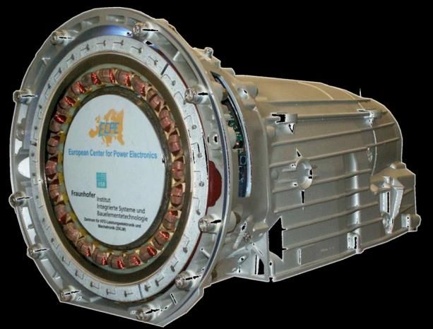
electronics – not as a short term stress, but for normal
operation. Under special operating conditions (e.g. coast-
ing of temperature) the coolant temperature can rise up to
120°C. Even if no output power is required from the power
electronics in this case, damage may not occur. The
ambient temperature in the engine compartment can rise up
to 125°C – close to the combustion engine up to 140°C.
All components have to be designed for these tempera-
tures.
When talking about the lifetime of automobiles, one must
distinguish between the active service life and the passive
life. The later is estimated about 15 years while the active
service life lasts about 10.000h, corresponding to a mileage
of about 300.000km. The active life is generally split in
several phases, e.g.:
Coolant temperature < 90°C for 95% of the active
service life
Coolant temperature > 90°C for 5% of the active
service life (max. 30 minutes en-bloc)
Fig. 1: Power control unit of the Toyota Prius II (top); Assuming a lifetime of about 15 years and two cold starts
combustion engine with the gear-box and the electric per day, meaning the coolant is heated up twice from 5°C
machines (bottom). (Source: Toyota) to 105°C and cooled down again, all components involved
have to sustain 11.000 passive temperature cycles with a
Mechatronic integration means that mechanics, power
shift of about 100K over their product life.
electronics, sensory and controls have to form a single
functional unit. Traditional interfaces between electronics Superimposed on these coolant temperature cycles are
and mechanics must be dissolved. However, the great active temperature cycles (s. Fig. 2). The distribution of the
challenge with any approach of mechatronic integration is amplitudes of the active cycles is a function of the time-
that it must be effective, not only with respect to system dependent power dissipation in each component, the heat-
size, but also regarding system costs, functionality, manu- ing by neighbouring components (both corresponding to
facturability, testability and reliability. the mission profile), the cooling conditions (thermal resis-
tance), and the individual thermal time constant of each
component.
2. Requirements on Inverter Drives in the The windings of the electric machine for example heat-up
to an average temperature that is considerably higher than
Automotive Powertrain
the coolant temperature. Modern insulation systems allow
Hybrid vehicles are classified as micro/mini hybrids (60kW) in terms of the contribution of the 100.000 cycles with a temperature amplitude of 20-30K
electrical drive system to the total traction power. In during a vehicle lifetime. The situation is quite different
brackets a rough estimation of the corresponding power
range of the electric drive system is given.
180 e.g. junction temperature of
With the exception of micro/mini hybrids and mild hybrids a power semiconductor chip
160
in the lower power range, water cooling is necessary for
Temperature [°C]
140
the electric motor and the power electronics. This is due to
120
the high power dissipation – even with highly efficient 100
components – and the high ambient temperature near the 80
ICE - OFF
ICE - ON
internal combustion engine (ICE). 60 Coolant
Because of size and cost reasons, future hybrid vehicles 40
should have only one single water-cooling cycle for all 20
Ambient
components – the combustion engine, the electric motor, 0
and the power electronics. Modern combustion engines -20
operate with a coolant temperature of up to 105°C, an -40
Time
increase up to 115°C is requested for ICE efficiency
reasons. This temperature also applies to any water-cooled Fig. 2: Thermal cycling during a typical vehicle run.
-2-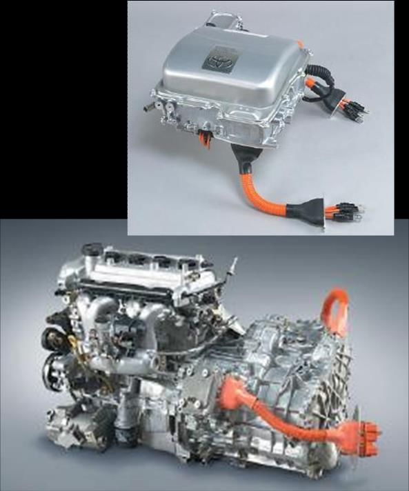
3. General Design Considerations

                            Auxiliary Power Supply
                            Protection / Diagnosis
                                                                                            Fig. 4 shows two basic concepts how to integrate power

                                CAN-Interface
                                 Drive Control                                              electronics into an electric machine. The left-hand side

                                  Gate-Driver
            EMC Filter

                                                                                            solution uses the ring-shaped area on the face of the stator
                                                                                 M          iron stack directly beside the stator windings. The design
                                                                                            on the right makes use of the ring-shaped volume radially
                                                                                            outside the stator iron stack.
                                                                                            The integration on the face of the stator generally allows a
                                                                                            larger diameter of the machine and with that a higher
Fig. 3: An inverter motor integrates the electric machine
                                                                                            torque. This design has been used in the first generation of
and all the power electronics (including dc-link capacitor,
                                                                                            our integrated electric drive units for hybrid traction [2].
control board and EMC filter).
                                                                                            Since the power electronics is very close to the hot stator
                                                                                            winding in this case, a sophisticated thermal shielding
for the semiconductors and their direct environment (bond
                                                                                            technique is necessary. A separation of the cooling jacket
wires, substrates, etc.), where the thermal time constants
                                                                                            in two series-connected channels is quite simple with this
are in a range of some milliseconds to a few seconds. Each
                                                                                            arrangement. If the cooling channel for the power electro-
acceleration and braking of the vehicle results in a tempe-
                                                                                            nics is connected to the coolant inlet, the temperature level
rature change. One must reckon with a much larger
                                                                                            of the electronics can be reduced by about 10K. This is
number of temperature cycles therefore - approximately
                                                                                            because in the power range typical for full hybrids
3.000.000 with an amplitude of 30…40K. It is obvious that
                                                                                            (30…60kW), the total power dissipation in the electric
under such operating conditions, system design for reliabi-
                                                                                            drive unit (power electronics plus electric motor) can in-
lity is an essential subject.
                                                                                            crease the coolant temperature by up to about 15K, assum-
Another great challenge of a mechatronic integration is the                                 ing a typical coolant flow rate of 8 liter/min.
complex structure of the package volume available for the
                                                                                            A thermal decoupling between motor and electronics with
electronics. This volume is generally predefined by the
                                                                                            respect to radiated and conducted heat is easier if the
mechanical requirements and not by the requirements of
                                                                                            water-cooling jacket is placed between the motor and the
the power electronics. In the case of an inverter motor
                                                                                            electronics as shown on the right hand side of Fig. 4. How-
there normally is only a ring-shaped volume around the
                                                                                            ever, the electronics is exposed to the full temperature
electric machine to be used for the integration, and - to
                                                                                            gradient between the coolant inlet and outlet in this case.
make matters worse - this volume is often additionally cleft
by studs and ribs. The structural conditions are therefore                                  An absolute prerequisite for achieving high power density
not comparable to conventional electronics. New approa-                                     and a high system reliability is that not only the power
ches for a 3D integration of power electronics and new                                      semiconductors, but all components are included in the
kinds of components with a higher structural flexibility are                                thermal system design. Many of the inverter components
prerequisites to meet the given challenges. This especially                                 (like capacitors, inductors, PCBs, etc.) are made of mate-
applies to all large volume passive components like the dc-                                 rials with poor thermal conductivity and therefore require
link capacitor and the EMC filter components (Fig.3).                                       special attention.

                                             E-Drive unit

                                                                                                                                       Clutch-box wall
                         electronics

                                                       Coolant jacket
                            Power

                                                                                                               DC-link
                                                                                                              capacitor           Power module
                                                     Stator iron stack
                                                                                                                          Coolant jacket
                                                      Stator winding
                                                                                                                      Stator winding

                                                        E-Machine
                                                                                                ICE housing
    ICE housing

                                                                         Clutch box

                                                          rotor                                                            E-Machine
                                                                                                                                                         Gear box

                                                                                                                             rotor

                                                          Clutch                                                              Clutch

Fig. 4: Two solutions how to integrate an inverter into an electric machine. Left: First generation system.
Right: Second generation system, which completely fits into an existing drivetrain of a passenger car.

                                                                                      -3-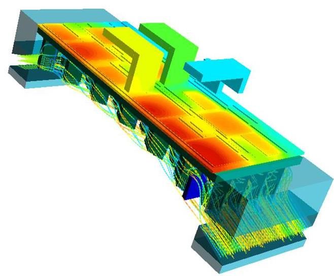
complete inverter according to Fig.3. But the conical, tuba-
shaped housing with internal studs and ribs considerably
complicated the integration challenges.
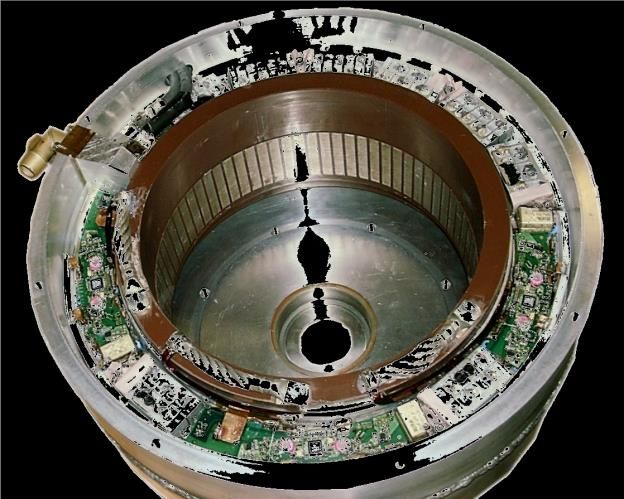
The basic internal arrangement of the components is
shown in Fig. 4 (right) and Fig. 6. A permanent magnet
excited synchronous machine (PM machine) provides a
very high power density and a high efficiency even in the
low speed range. By using a whole-coiled winding (single
teeth coils), the winding overhang could be greatly re-
duced, resulting in an increased active motor length. The
torque disadvantage, caused by the conical housing and the
thereby restricted motor diameter, could be equalized this
way. The electrical circuitry of the motor windings corres-
ponds to that of a classical three phase machine. Thus only
three power interconnections between motor and inverter
Fig. 5: View on the first generation system: stator with are necessary. Multi-functional winding interconnections
integrated inverter (90kVA, 400V). prevent a heat transfer out of the hot windings into the
power electronics.
Two of the essential criteria for the thermal system design In order to achieve an optimum usage of the available
are the heat flux density and the temperature headroom. package volume, a ring-shaped dc-link capacitor has been
The later means the difference between the maximum developed in cooperation with the Epcos AG. This capaci-
operating temperature of the component and the maximum tor provides a capacitance of 500µF (450V). Its concentric,
coolant temperature. The higher the heat flux density pro- nearly coaxial terminals form the dc-link bus-bar and allow
duced by the individual component and the lower the the realization of a very low parasitic dc-link. The ripple
temperature headroom, the tighter must be the thermal current rating of this capacitor is several hundred amperes
coupling to the heatsink, e.g. the water-cooling jacket. and thus far beyond the actual ripple current load. The self-
Typical heat flux densities lie in the range of 50...200 heating, caused by the inverter ripple current, is therefore
W/cm2 for power semiconductors, 0.1...3W/cm2 for mag- negligible. However, in order to protect the capacitor
netic components and below 0.1W/cm2 for capacitors [3]. against the high ambient temperature of up to 140°C, it is
thermally coupled to the cooling jacket.
For each inverter component the mechanical design must
ensure proper heat conducting paths. The design para-
meters in this context are the heat conducting cross-
section, the heat path length, and the heat path material.
Sealing materials, like e.g. soft silicone compounds, not
only ensure protection against contamination and vibration,
DC-link
but can also provide a more homogeneous temperature dis-
Capacitor
tribution and thus greatly improve the thermal situation
within the power electronics.
Power
4. Towards an Integrated Inverter Drive Modules
Fig. 5 shows the stator of the first generation drive system
with integrated power electronics. An induction machine
with a standard three-phase winding was used [2]. The
large winding overhang gave space for the electronics, but
also reduced the active motor length. The electrical drive
unit was integrated into a housing to be mounted between
the internal combustion engine (ICE) and the gear-box, and
Clutch
thus increased the total length of the drivetrain.
Box
For the second generation system there was a strong re- Stator
quest for a solution that completely fits into the existing
drivetrain of a passenger car. The clutch-box was desig- Coolant
nated as the housing, in which an electrical drive unit with
a mechanical output power of 50kW and a maximum Fig. 6: X-ray view on the second generation inverter drive
torque of 220Nm had to be integrated, together with the (50kW), integrated into the clutch-box of a passenger car.
-4-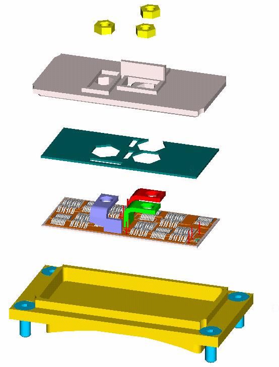
As can be seen from Fig. 6, three half-bridge power
modules are placed at the periphery of the water cooling
jacket that surrounds the whole electric machine. The re-
maining sections at the periphery are used for the control
board, the current sensors and the EMC filter. Since the
system is also intended as a test platform for different
power module designs, special attention has been put on a
modular and assembly friendly construction.
Fig. 7 shows an exploded view on the first application
specific smart power half-bridge module. The power semi-
conductors are mounted on an AlN DCB substrate that is
soldered on a directly water-cooled base-plate. Equipped
with 600V-IGBT chips from Infineon, each module is able
to control an AC current of 320ARMS at a switching fre-
quency of 8kHz, a coolant temperature of 115°C, and a         Fig. 8: Thermal optimization with 3D computational fluid
DC-link voltage of 450V.                                      dynamcis simulations.
The gate drivers are galvanically insulating and offer
extensive protection and diagnosis functions. Placed within   back-side structure of the modules is necessary in order to
the power module, only 2mm above the IGBT bond wires,         minimize the thermal resistance between the power semi-
the gate drive electronics is exposed to very hard thermal    conductors and the coolant, but not to exceed the maxi-
and electromagnetic operating conditions. With the driver     mum allowable coolant pressure drop. The cooling effi-
concept described in [4], a very stable and safe operation    ciency of a finger-structure varies with its geometry -
of the power modules could be ensured. A prerequisite for     namely the finger thickness, shape, height and surface - as
a reliable operation under the given high-temperature         well as the spacing and arrangement of the fingers. This
conditions is the consistent abandonment of temperature       optimization (s. Fig. 8) was realized with the 3D compu-
sensitive components, like opto devices or wet electrolytic   tational fluid dynamics software Flotherm™. An important
capacitors.                                                   issue in this context is that the parameters of the coolant,
                                                              especially the viscosity of the water-glycol mixture (to
Special attention has been payed to an optimized thermal
                                                              down on 50:50), greatly vary along with the temperature.
design of the power modules. The inverter drive is inserted
in the existing coolant cycle of the ICE. The available       The realized power modules showed a specific thermal
coolant flow is about 8 liter/min and the maximum allow-      resistance junction-coolant (Rth,jc) of 0,45Kcm2/W at a
able total pressure drop 200 mbar. An optimization of the     coolant flow rate of 8 liter/min and a pressure drop of
                                                              60mbar, both of which were close to the predictions from
                                                              simulation. With respect to the coolant flow, the three
                                                              power modules are connected in series, thus the specifi-
                                                              cation of a total pressure drop of 200 mbar was achieved.
                                                              The prototype was built on a machined Cu base plate. This,
                                                              of course, is no solution for series production, partly
                                                              because of cost issues, but mainly because of reliability
                Insulatin                                     issues of the DCB to base plate solder joint. Due to the
                         g   Gate Driv
                                      er                      passive temperature cycles to be sustained (ca. 11.000
                                                              cycles with a mean temperature swing of ca. 100 K), an
                                                              AlSiC base plate could be a choice to reduce the thermal
                                                              mismatch between base plate and DCB substrate to an
                                                              acceptable low level at a small expense of thermal
                                                              efficiency.
               Power S
                        emicond                               Power cycling is another reliability issue, which has been
                               uctors
                                                              met by the thermal design efforts. At nominal operation,
                                                              the junction temperature rise has been verified with
                                                              approximately 40 K. The requirement of about 3.000.000
                                                              cycles is therefore within the order of magnitude of experi-
                    Base pla                                  mental results (s. Fig. 9).
                             te

Fig. 7: Intelligent power module with integrated gate
driver and direct liquid cooling.

                                                        -5-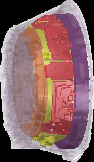
200 Nf 5% VCE Tm=60°C and package volume that had been considered as absolute-
180 Nf 5% VCE Tm=80°C
160 Nf 5% VCE Tm=100°C ly useless for high power electronics so far. 3D integration,
140 passive tests new components and sophisticated thermal management
active tests
120 solutions opened the way to a system with unique power
temperature swing T [K]
Coffin&Manson = 2 T
C=0.5
100
C=1
density. The next steps aim on a further optimization of the
80 C=0.5, y = 20 MPa system reliability, manufacturability, and modularity.
C=1, y = 30 MPa
60
6. Acknowledgment
40
The development of the drive system has been funded by
Bond Wire
Fatigue Limit ECPE in the framework of the demonstrator program
“System integrated drive for hybrid traction”. The authors
20
4 5 6 7 8
would like to thank ECPE as well as the state of Bavaria
10 10 10 10 10
cycles to failure Nf
for supporting this work.
Fig. 9: Experimental results and model calculations of
the bond wire fatigue limits ([5], [6]).
The control board of the inverter (s. Fig. 10) comprises an
IFX XC164 microcontroller, a CAN-Bus and a resolver
interface, the auxiliary power supply, and additional signal
conditioning circuits. The power supply is designed to
meet the input voltage requirements of a 12V automotive
power-net. In order to ensure a close thermal coupling to
the coolant and with that highly efficient cooling, a semi-
flex design has been chosen to perfectly fit the motor
contour. An all SMT design allows to glue the control
board on adequate flat surfaces of the cooling jacket. A
semi-IMS substrate with superior thermal properties is
formed this way.
A picture of the electric drive unit is given in Fig. 11. The Fig. 11: Electric motor and drive inverter, both integrated
maximum mechanical power of this unit is 50kW, the into the clutch-box of a passenger car. The picture shows
maximum torque 220Nm. With a total package volume of the drive unit srewed at the gear-box.
the inverter of 1.3dm3 and an apparent power of 100kVA,
the power density of the electronics reaches 75kVA/dm3 7. References
(i.e. 1.1kVA/in3).
[1] Tadano H., TOYOTA Central Research and Develop-
ment Laboratory: Power Devices and Systems in
Automobile, Proc. of CIPS, Bremen, 2000
5. Conclusions
[2] Tadros Y., Ranneberg J., Schäfer U.: Ring Shaped
Simultaneous engineering (electrical, mechanical, thermal) Motor-Integrated Electric Drive for Hybrid Electric
is an imperative prerequisite for a mechatronic integration Vehicles. Proc. of EPE Conf., Toulouse, 2003
of power electronics. Consistently following this way, an [3] Maerz M.: Thermal Management in high-density
inverter drive for hybrid traction could be integrated into Power Converters. Proceedings of ICIT Conference,
the clutch-box of a passenger car, i.e. in an environment Maribor, 2003
[4] Zeltner H., Maerz M., Billmann M., Schimanek E.:
A compact IGBT driver for high temperature appli-
cations. Proceedings of PCIM Conference, Nurem-
berg, 2003
[5] Poech M.H., Dittmer K.J., Gäbisch D.: Investigations
on the damage mechanism of aluminium wire bonds
used for high power applications. Proceedings of
EuPaC'96, Essen, Germany, 1996
[6] Held M., Poech M.H., et al.: Fast power cycling test
of IGBT modules in traction application. Proceedings
Fig. 10: The application specific designed control board of 2nd Intern. Conf. on Power Electronics and Drive
perfectly fits the motor contour. Systems, Singapore, 1997
-6-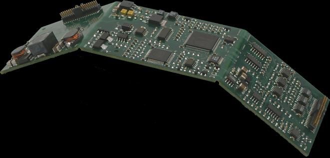
You can also read