IEEE IROS 2021 (accepted paper) - Parallel Variable Stiffness Actuators - Vanderbilt University Labs
←
→
Page content transcription
If your browser does not render page correctly, please read the page content below
IEEE IROS 2021 (accepted paper)

                                    Parallel Variable Stiffness Actuators
                                             Chase W. Mathews and David J. Braun

   Abstract— In this paper, we introduce a new type of compli-
ant actuator named the Parallel Variable Stiffness Actuator
(PVSA) which consists of a variable stiffness spring placed
in parallel with a direct-drive motor. Parallel variable stiff-
ness actuators provide (i) high-fidelity force control and (ii)
controllable energy storage, as they inherit the benefits of
direct-drive motors and variable stiffness springs. We present
a compact design of the PVSA using a flat motor connected
to an adjustable mechanical advantage torsional spring. We
show that this PVSA is (1) not subject to the fundamental
force control bandwidth limitation of series elastic and variable
stiffness actuators, and most notably, (2) enables resonant
energy accumulation despite the limited deformation of the
spring and the constrained motion of the load attached to
the actuator. The latter differentiates parallel variable stiffness
actuators from fixed-stiffness parallel elastic actuators. PVSAs
may be used with smaller direct-drive motors to match the peak
power of larger motors without compromising force control
fidelity. PVSAs may be used to implement resonant forcing
under joint angle limitations in walking, jumping, running,                  Fig. 1.   Prototype parallel variable stiffness direct-drive actuator.
swimming robots, or robotic exoskeletons used to augmented
human motion in the aforementioned tasks.

                        I. I NTRODUCTION                                  Because of these limitations, SEAs and VSAs are not well
                                                                          suited for high-energy tasks.
   Compliant actuators have demonstrated potential in the                    For most actuators, there is a trade-off between torque
areas of industrial robot safety, rehabilitation devices, and             density and compliance. Gears are typically used to increase
mobile robots [1]. One of the most common compliant                       the torque density of electric motors, but come with the cost
actuators is the Series Elastic Actuator (SEA); in its most               of lower efficiency, reduced precision, and slower response
basic arrangement, the SEA is the addition of an elastic                  times [2]. Thus, it is desirable to minimize the gearing when
element (e.g. a spring) between the load and the primary                  possible. Recent developments of torque-tense motors have
actuator (e.g. a motor) [2]. The passive compliance of the                enabled the use of low gearing or even direct drive robotic
spring functions to protect the primary actuator (typically               joints. For example, the MIT Cheetah [11] is a quadruped
highly geared) from shock loads, allow safe force control                 robot which runs using highly backdrivable motors. Direct-
of the load, and store elastic potential energy [3]. SEAs                 drive motors still have much lower torque density than
can be found in devices such as as ankle prostheses [4],                  comparable gearmotors. One way to amplify output torque
knee prostheses [5], and powered arm exoskeletons [6].                    of a motor without compromising efficiency or compliance
One modification the SEA is the Variable Stiffness Actuator               is to use a mechanical spring in parallel with the motor, i.e.
(VSA), in which a Variable Stiffness Spring (VSS) is used                 a Parallel Elastic Actuator (PEA). PEAs have demonstrated
in place of a fixed-stiffness spring [7]. The variable passive            lower energy consumption and peak power requirements as
compliance allows for control of frequency response and                   compared to SEAs [12]–[15] Parallel elasticity especially
actuation speed, and has been used in ankle exoskeletons                  shows promise in assistive devices since the elastic elements
[8], [9] and robotic joints [10]. However, series compliant               can offload force from the muscles; for example, a walking
actuators have a few pitfalls that limit their practicality in hu-        exoskeleton [16] and a jogging exoskeleton [17] utilized
man augmentation and robotic devices: (i) it is energetically             parallel elastic elements to reduce metabolic energy cost.
expensive to generate force without motion, (ii) all force                One limitation for PEAs is the use of fixed stiffness springs;
generated by the motor must first pass through the spring,                fixed stiffness springs only promote efficient cyclic motion
which limits the force control bandwidth of the actuator.                 at one resonant frequency and it is energetically expensive
  Chase W. Mathews and D. J. Braun are with the Advanced Robotics and     to oscillate at different frequencies.
Control Laboratory within the Center for Rehabilitation Engineering and      In this paper, we introduce a new class of Parallel Variable
Assistive Technology, Department of Mechanical Engineering, Vanderbilt    Stiffness Actuators (PVSAs) which consist of a direct-drive
University, Nashville, Tennessee 37235, USA.
  E-mail: chase.w.mathews@vanderbilt.edu                                  motor arranged in parallel with a variable stiffness spring
  E-mail: david.braun@vanderbilt.edu                                      (Figure 1). The PVSA provides high fidelity force control
(a) Parallel Variable Stiffness                           (b) Parallel Elastic                                     (c)   Series Elastic
                x                                                                                                          qM
      m              k(x)                                                   k                                                                    q
                                                                                                                                     k

                                                                                             Load                  M
     M          q
                                                            M          q

Fig. 2. Compliant actuators driven by a large motor (M) that generates force and supplies energy and one small motor (m) that modulates the stiffness
of the spring in parallel variable stiffness actuators; q denotes the position of the load, x is the position of the small motor while qM is the position of the
motor in series elastic actuators.

and controllable energy storage with inherent compliance.                            The relation between the stiffness of the actuator k and
For cyclic motions, the PVSA has the ability to amplify                           the position of the motor x that modulates the stiffness of
the mechanical power of the direct-drive-motor by using the                       the spring, depends on the stiffness modulating mechanism
spring as a mechanical energy storage reservoir. The VSS                          [19]. For example, the following relations
has the unique ability to modulate the resonant frequency                                                            c0           c0
of the system; this expands the power amplification space                                  k(x) = c0 + c1 x, k(x) = , k(x) = 3             (3)
                                                                                                                      x           x
to include frequency modulation, instead of the more typi-
cal amplitude modulation to accumulate energy. Frequency                          define the stiffness of an antagonistic stiffness modulator
modulation allows for kinetic energy accumulation under                           [20], [21] where x is the extension of the spring, a helical
motion constraints, such as in jumping , which is important                       spring [22], torsional leaf-spring [23] or a bending leaf-
for robots and devices subject to joint angle limitations [18].                   spring [24] where x is the length of the spring.
   We present a compact design of a PVSA which has
                                                                                  B. Force Control and Resonant Forcing
high motor power to weight ratio, high energy storage to
weight ratio, and large range of stiffness change. Our design                        In this section, we demonstrate the main benefits of
features a modular architecture where the variable stiffness                      PVSAs which are (i) high fidelity force control compared
mechanism is connected to a motor similar to how a gearbox                        to SEAs and (ii) resonant forcing under motion constraint
is connected to a motor, and where springs with different                         when compared to PEAs.
energy storage capacity and stiffness can be interchanged                            (i) High fidelity force control: In PVSAs, the force of
similar to gearboxes with different gear ratios.                                  the driving motor F is directly applied to the load, similar
                                                                                  to direct-drive actuators. Consequently, assuming an ideal
     II. PARALLEL VARIABLE S TIFFNESS ACTUATORS                                   feedback loop, the force control bandwidth is infinite. In
   The PVSA consists of two main components placed in                             practice, finite sampling times limit the force control band-
parallel: a variable stiffness spring (VSS) and a direct drive                    width of PVSAs (Fig. 2a) the very same way as they limit the
motor (DDM). A conceptual model of a PVSA is shown in                             force control bandwidth of direct-drive actuators. However,
Fig. 2a together with two alternative actuators: the parallel                     the bandwidth is only dependent on the time constant of the
elastic actuator (PEA) Fig. 2b, and the series elastic actuator                   motor current dynamics while it is independent of the time
(SEA) Fig. 2c.                                                                    constant of the motor position dynamics. The same does
                                                                                  not apply to series elastic actuators (Fig. 2c) or the more
A. Mathematical Model
                                                                                  general class of variable stiffness actuators [11] (not shown in
   In this section, we present one of the simplest models                         Fig. 2), as in both of these actuators, the motor force cannot
of PVSAs. The model consists of (1) a larger direct drive                         be directly applied to the load; it can only be applied through
motor (M) – pure force generator – that acts on the load,                         the spring. As a result, the force control bandwidth in series
(2) a variable stiffness spring that acts on the load, and (3)                    elastic and variable stiffness actuators is determined by the
the stiffness modulating mechanism driven by a small motor                        time constant of the motor position dynamics which may be
(m). The equations that govern the dynamics of the load and                       three orders of magnitude larger (fraction of a second) than
the stiffness modulating mechanism are given by:                                  the time constant of the motor current dynamics (fraction
                            M q̈ + k(x)q = F                               (1)    of a millisecond). The difference between the force control
                                                                                  bandwidth of a PVSA compared to a SEA (or VSA) can be
                            1 dk(x) 2                                             best exemplified by a task that requires resonant forcing.
                         mẍ +       q = Fm                     (2)
                            2 dx                                                     (ii) Resonant forcing: Let us assume that we aim to
where M is the mass of the load, q is the position of the                         generate oscillatory motion of a robot limb, similar to the os-
load, k is the spring stiffness, x is the position of the stiffness               cillatory motion of the hip in human running or swimming. In
modulating motor, F is the external force acting on the load,                     this task, we may assume that the oscillations start with low
m is the mass of the stiffness modulating mechanism while                         frequency, corresponding to jogging or casual swimming,
Fm is the motor force.                                                            while they end at a high frequency, as in sprinting. Also, we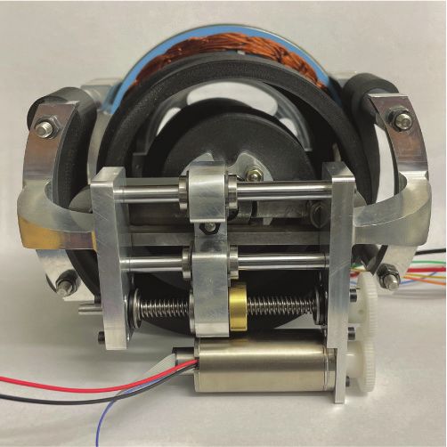
(a) Parallel Variable Stiffness                              (b) Parallel Elastic                                 (c) Series Elastic
         1

                                                        1

                                                            F/Fmax
q/qmax

         0                                              0
                                                       -1
     -1
         1
                                                                                    Motor force
k/kmax

                                                                                    Load position
                                                                                    Spring stiffness
         0
                                                                                    Time

Fig. 3. Resonant forcing of a linear oscillator using (a) a parallel variable stiffness actuator, (b) a parallel elastic actuator, and (c) a series elastic actuator.
The actuators are assumed to have instantaneous force generation and stiffness modulation. In the case of the SEA, the force generation is filtered through
general closed-loop positioning dynamics of the motor.

aim to achieve this task using a weak, force limited actuator,                      where n and n + 1 denote the current and the next half
similar to a force limited muscle, and we aim to ensure that                        oscillatory cycles. Assuming k0 = kmin and kn < kn+1 , the
the amplitude of the oscillatory motion does not exceed a                           frequency of the oscillations will increase according to the
set constraint which may be interpreted as a motion range                           following relation:
or joint angle limitation in robots or humans.                                                                                  !−1
   Resonant forcing is a useful method of actuation using a                                             1      1          1
                                                                                                 fn = √      √ +q                            (9)
fast but weak actuator. These are the main characteristics of a                                       π m      kn      kn + 2Fn           qmax
typical direct-drive motor. Here we assume that bandwidth of
the ideal motor is infinite while the motor can only produce                        Therefore, by changing the stiffness of the spring kmin ≤
limited force:                                                                      k0 < k1 < ... < kn < ... < kN ≤ kmax , we may reach a desired
                                                                                    frequency fd in finitely many oscillations N, and maintain the
                            F ∈ [−Fmax , Fmax ].                            (4)
                                                                                    desired frequency using zero force and the optimal stiffness:
Resonant forcing also requires a spring with sufficient energy
                                                                                                                                     4    1
storage capacity. The energy storage capacity of a typical                                          fd = fN , FN = 0, kN =                   ≤ kmax .          (10)
                                                                                                                                   π 2m   fd
linear spring is defined by its stiffness and the maximum
allowable deflection of the spring E ≤ Emax = 12 kq2max . Here                      Increasing the frequency of the oscillations while the ampli-
we assume that the stiffness of the spring can be changed in                        tude is maintained constant (6) leads to energy accumulation
a finite range and that the deflection of the spring is limited                     Emin ≤ E0 < E1 < ... < En < ... < EN ≤ Emax . Maintaining the
                                                                                    constant amplitude condition (6) is possible if the minimum
              k ∈ [kmin , kmax ] and q ∈ [−qmax , qmax ].                   (5)     amount of energy exceeds a lower limit E0 ≥ 12 kmin q2max while
   In resonant forcing, the motor force F = ±Fmax is applied                        the maximum amount of energy does not exceed the energy
as a constant, where the direction of the force changes at                          capacity of the spring EN ≤ 21 kmax q2max .
every peak of the load position q (see Fig. 2a). In this way,                          In this section we have demonstrated the principle of
the amplitude will grow without bound (assuming no energy                           constant amplitude resonant forcing achievable by a PVSA
dissipation), thereby, the constraints on the load position                         by assuming the simplest linear spring and no energy dis-
q(t) ∈ [−qmax , qmax ] may not be maintained at all times t.                        sipation. The same principle extends to weakly dissipative
However, we may limit the amplitude of the oscillator to                            nonlinear oscillators [25], and may be useful to accumulate
ensure the second condition in (5), or even maintain the                            energy – increase the frequency of an oscillatory limb motion
amplitude of the oscillator at every cycle                                          subject to joint angle limitation – in robots driven by small
                                                                                    motors.
             max q(t) = qmax and min q(t) = −qmax ,                         (6)
               t                               t
                                                                                    C. Comparison to Other Compliant Actuators
by changing the stiffness of the spring when it does not store
energy q ≈ 0. The energy balance of the system shows the                               In order to compare PVSAs to PEAs and SEAs, we assume
relation between the stiffness kn , external force Fn , and the                     that all three have the same energy storage capacity, and
maximum amplitude of oscillations qmax :                                            that the maximum motor force is also the same in all these
                                                                                    actuators shown in Figs. 2 and 3.
                          1             1
  En+1 = En + Fn qmax ⇒ kn+1 q2max = kn q2max + Fn qmax (7)                            Compared to PVSA (Fig. 3a), the ability of a SEA to
                          2             2                                           accumulate energy is tied to the closed loop position control
From (7), a relationship between amplitude, resonant forcing,                       bandwidth of the motor. SEAs typically use highly geared
and stiffness is established:                                                       motor drives with position control in order to create a
                                    2Fn                                             position differential between the load and the motor. The
                      kn+1 = kn +       .                   (8)
                                   qmax                                             maximum work done by SEA depends on its position control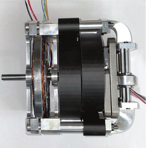
(a) PVSA Prototype                (b) CAD Section View                                             (c) VSM Design                 (d) VSM Model
             142 mm                                                                                           152 mm
                                                                                                                                          x

                                                                Variable Stiffness Mechanism (VSM)
                                                                                                          x                                                   θinput

                                                                                                                               θspring
                                       Motor    Spring

Fig. 4. (a) Top down view of the PVSA prototype. (b) Cross-sectional CAD view of the PVSA prototype. (c) Back view of the constructed prototype.
(d) Model of the variable stiffness mechanism (VSM).

bandwidth which may be three orders of magnitude lower                                               A. Variable Stiffness Spring Mechanism
than the force control bandwidth of the motor. Because of                                               The variable stiffness mechanism (Fig. 4c,d) is based on
this, the SEA take more cycles than the PVSA to accumulate                                           an adjustable mechanical advantage based design such as
the same amount of energy (Fig. 3c).                                                                 in the AwAS and AwAS-II [26]. The variable pivot point
   Compared to the PVSA (Fig. 3a), the PEA can do less                                               design was chosen because the energy storage of the device
work in every cycle, and thereby, needs more cycles to                                               is independent of the stiffness. This is not true for VSS
accumulate the same amount of energy (Fig. 3b). The max-                                             mechanisms where the effective length of the spring is
imum work done by PEA is Fmax qmax,n ≤ Fmax qmax where                                               changed to modulate stiffness [27]. If the pivot point drive
the amplitude can only gradually increase according to                                               train passively locks, then the VSS is able to maintain a
                                       Fmax                                                          certain stiffness passively. This is why an antagonistic VSS
                qmax,n+1 = qmax,n +         ≤ qmax .                                                 setup was also not chosen, as it requires increasing energy
                                       kmax
                                                                                                     to maintain a given stiffness [7].
Because of this, the PEA takes twice as many cycles than the                                            Assuming small-angle deflections, the stiffness of the
PVSA to accumulate the same amount of energy (Fig. 3a,b).                                            variable pivot point spring (Fig. 4d) can be represented with
   The higher number of cycles could be detrimental for tasks                                        the following equation:
with collision or hysteretic losses. Depending on the system
                                                                                                                                             x 2
natural frequency, the ability of the motor to apply force may                                                            k(x) = kspring (      )             (11)
                                                                                                                                           l −x
be attenuated as well since the system is always operating at
the spring resonant frequency. In some tasks, the limitation                                         where kspring is the stiffness of the spring, x is the position
on the range of motion by stiff springs may cause instability                                        along the lever arm, and l is the length of the lever arm.
problems; for example, a higher stiffness ankle exoskeleton                                          According to this equation a large range of stiffness is
as developed in [16] actually increased metabolic cost, likely                                       achievable; theoretically the range of achievable stiffness is
due to an interference with muscle coordination. Researchers                                         [0, ∞] (if the pivot point is placed at the ends of the lever
have mitigated these problems in parallel elasticity to some                                         arm).
extent by using a nonlinear dual-stage spring [14]; however,                                            The equation of motion for the small stiffness modulating
the spring resonance must be optimized for a specific task.                                          motor (2) is the following:
The PVSA would work best for tasks that (i) need full range                                                                               x
of motion while accumulating energy and (ii) are subject to                                                          mẍ = −kspring l          q2 + Fm          (12)
                                                                                                                                      (l − x)3
disturbances and variance.
                                                                                                        This equation shows that when the deflection of the spring
                   III. D ESIGN OF THE PVSA                                                          is zero (when the spring does not store energy) a small
                                                                                                     motor can change the stiffness of the spring without working
   In this section, we present a prototype PVSA (Fig. 4a).                                           against the spring. If the device is self locking, such as
The prototype is composed of the variable stiffness spring                                           with a lead-screw, the force required to maintain position
mechanism, a custom made fiberglass spring, and a direct                                             by the motor Fm is zero. Because of these two features, a
drive motor (Fig. 4b). The prototype was designed based on                                           small and lightweight motor can be used to drive the VSS
the following four objectives:                                                                       mechanism. Because the modulation motor must be operated
  1)   Maximize energy storage capacity of the actuator.                                             at a small range around zero deflection, ±θinc , the amount
  2)   Minimize energy losses of the actuator.                                                       of stiffness change per cycle depends on the load speed and
  3)   Maximize volumetric efficiency; similar to a gearbox.                                         the motor speed. The modulation drive must be fast enough
  4)   Make a modular design, such that the spring can easily                                        to increment position within the entire range of oscillation
       be interchanged to fit system requirements.                                                   frequencies expected. Given a maximum load frequency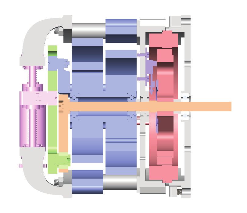
ωmax and amplitude A, the desired positioning time α (the           C. Direct Drive Motor
time it takes to increment stiffness kn to kn+1 ) must satisfy         The direct drive motor should be selected based on geom-
α < 2θinc /(Aωmax .). The maximum force requirements of             etry and power requirements; generally, the torque capability
the drive are set by ±θinc according to (12).                       of a motor is proportional to its diameter. The function of
   To convert the lever arm mechanism from a linear dis-            the drive motor in the PVSA is twofold: (1) it must generate
placement mechanism to an angular displacement mecha-               enough torque to overcome system damping and (2) it must
nism, two linkages were added at each end to relate input           apply torque to change stiffness kn+1 − kn ∝ Fn according
angle to the spring deflection angle as depicted in Fig. 4d.        to (8). Therefore, the minimum motor torque in PVSA
Since the link at each end of the lever arm both connect            is defined by system damping, while the maximum motor
back to the same axis of rotation, the center of a torsion          torque defines the transient time required for the system to
spring can be mounted about an arbor on the main shaft. This        reach the desired oscillation frequency. Unlike in a direct
arrangement also allows the linkages to fit into a cylindrical      drive actuator, the motor torque does not define the maximum
footprint.                                                          torque of the parallel variable stiffness actuator .
   A lead screw drive was chosen as the pivot positioning              We use an Allied Motion MF0127008 brushless frameless
actuator since it is self-locking. A direct driven Maxon DCX-       motor (Fig. 4a,b) which has a continuous torque rating of
22L motor was used for the lead screw modulator. The                1.6 Nm and a motor constant of 0.296 Nm/A. The housing
range of mechanical advantage adjustment of this spring was         both supports the stator of the motor and the springs. The
found through a geometric analysis of the linkages. In the          springs and stiffness modulator mechanism were attached to
specific mechanism design as shown in Fig. 4d, the range            the back of the motor shaft while the output of the actuator
of mechanical advantage achieved was [0.39, 2.8].                   is at the front of the shaft. An AMS AS5304A offset-axis
                                                                    magnetic encoder and axial magnet were placed inside of the
B. Spring Design
                                                                    rotor for precise position measurements.
   Because the variable stiffness mechanism uses an ad-
justable mechanical-advantage design, any torsion spring            D. Overall Design
form factor would work. The main design goals of the                   The mechanical design (Fig. 4) satisfies all of the initial
spring are to (1) maximize energy storage per volume, (2)           design objectives by (1) using torsion spiral springs, (2)
demonstrate low hysteresis, and (3) be easily manufactured.         using a self-locking stiffness modulator, (3) having little
We selected a spiral torsion spring, these springs demonstrate      unused space within the actuator volume, and (4) allowing
large volumetric energy storage densities as a long length of       easy swapping of the three components, motor, spring, and
spring can be coiled in a compact manner. The base torsional        stiffness modulator depending on task.
stiffness kspring can be modeled as the following [28], [29]:
                                                                                         IV. E VALUATION
                                   Ebh3                                The analytical investigation presented in Section II was
                         kspring =                          (13)
                                    12L                             based on several simplifying assumptions, such as instanta-
where E is Young’s modulus, b is the spring width, h is the         neous force generation of the motor, instantaneous stiffness
spring thickness, L is the effective length of the spring.          change, and zero damping. In this section we investigate the
   The spring will operate in the elastic regime for small          performance of our PVSA actuator using a simple experi-
deflections. If the spirals are spaced far enough at this deflec-   ment that is not subject to the aforementioned assumptions.
tion, the spring also avoids colliding with itself which causes     In the experiment, a pendulum (0.4m long and 2kg) was
nonlinear stiffness effects and reduced efficiency. Flat spiral     attached to the PVSA, and the actuator was used to speed
springs do not have the same properties in counterclockwise         up the oscillation of the pendulum from its natural frequency
rotation as in clockwise rotation, one way to account for           of 0.9Hz to a desired frequency of 2Hz while maintaining an
this is by de-clutching the springs during extension [30].          amplitude of ±30deg. This experiment was used to emulate
However, this results in a lower energy density since one           the speeding up of leg swing from walking and running.
spring is disengaged at all times. Another way is to mount             A controller was implemented to switch the direction
two springs in opposite configurations such that one is in          of the drive motor’s torque based on the motion of the
extension and one is in compression. In this setup, the             pendulum, such that the motor always applies torque in
stiffness will average out for both directions.                     resonance with the motion of the pendulum. The stiffness
   Another advantage of spiral torsion springs is the ease          increment was made smaller than expressed in (8) to allow
of manufacturing; the flat design is ideal for 3D printed,          the motor to overcome both the stiffness increment and
rolled, or cast materials. With the development of continuous       system damping (systems with lower damping would be able
fiber fabrication (CFF), strands of fiberglass can be laid along    to use more aggressive stiffness increments). The stiffness
the length of the spiral spring. We use continuous fiberglass       modulator was set to increment stiffness within a range
to fabricate the springs shown in Figure 4a,b. 3D printed           of ±5deg and used a simple PD controller to regulate the
continuous fibers demonstrate similar mechanical properties         position of the pivot point, see Fig. 4c,d.
to 6061 Aluminum alloys with the design freedom of 3D                  The results are shown in Fig. 5 for the position, motor
printing.                                                           input, spring stiffness, PVSA torque, and electrical power
(a) Experimental Setup consumption during a representative trial. The motor torque
was calculated by multiplying the instantaneous drawn motor
current by the motor constant. The PVSA torque was esti-
PVSA mated by separating out the gravitational torque contribution
of the pendulum τPVSA ≈ ml 2 θ̈ + mgl sin θ , where m is the
mass of the pendulum and l is the distance from the shaft
to the center of the weight Fig. 5a. The electrical power
consumption was calculated by multiplying the consumed
current by the supply voltage. Figure 5 shows that the PVSA
is able to (i) accumulate energy within a set motion range
limitation by increasing the frequency of the oscillations
0.4 m ±30°
with negligible energy cost from the stiffness modulator
(Fig. 5b,c,e-green), (ii) amplify the torque produced by the
actuator 15 times within 16s (Fig. 5d), and (iii) maintain fast
oscillations with a steady state power consumption of 30 W
2 kg (Fig. 5b,e-red). This power consumption is a likely a result
of composite spring hysteresis and motor inefficiency.
(b) 40
V. C ONCLUSION
20 This work presented a parallel variable stiffness actuator,
Angle (deg)
which has the ability to accumulate energy in resonance
0 while regulating a desired amplitude. A modular and compact
actuator was designed such that it can be incorporated into
-20
a range of cyclic tasks. The actuator was tested in an
-40 experiment to demonstrate the feasibility of the resonant
(c) 30 energy accumulation under motion range limitations and
High Stiffness (Frequency) realistic timing and damping conditions. In future work, we
Position x (mm)
aim to use the PVSA concept in a novel hip-joint exoskeleton
20 Stiffness Change
Window to increase swing leg frequency where the spring assistance
torque is modulated as a function of the user’s walking or
10 running speed.
Low Stiffness (Frequency)
0 R EFERENCES
[1] V. R. Ham, T. G. Sugar, B. Vanderborght, K. W. Hollander, and
(d) 20 PVSA Torque D. Lefeber, “Compliant actuator designs: Review of actuators with
Motor Torque passive adjustable compliance/controllable stiffness for robotic appli-
Torque (Nm)
10 cations,” IEEE Robotics and Automation Magazine, vol. 16, no. 3,
pp. 81–94, 2009.
0 [2] G. Pratt and M. Williamson, “Series elastic actuators,” Proceedings
1995 IEEE/RSJ International Conference on Intelligent Robots and
-10
Systems. Human Robot Interaction and Cooperative Robots, pp. 399–
-20 406, 1995.
[3] J. Hurst, A. Rizzi, and D. Hobbelen, “Series elastic actuation: Potential
and pitfalls,” International Conference on Climbing and Walking
(e) Robots, 2004.
40
Drive Motor [4] B. Convens, D. Dong, R. Furnemont, T. Verstraten, P. Cherelle,
Stiffness Modulator D. Lefeber, and B. Vanderborght, “Modeling, design and test-bench
Power (W)
validation of a semi-active propulsive ankle prosthesis with a clutched
series elastic actuator,” IEEE Robotics and Automation Letters, vol. 4,
20
no. 2, pp. 1823–1830, 2019.
[5] E. J. Rouse, L. M. Mooney, E. C. Martinez-Villalpando, and H. M.
Herr, “Clutchable series-elastic actuator: Design of a robotic knee
prosthesis for minimum energy consumption,” IEEE International
0 Conference on Rehabilitation Robotics, no. 1122374, pp. 1–6, 2013.
0 2 4 6 8 10 12 14 16 [6] D. Ragonesi, S. Agrawal, W. Sample, and T. Rahman, “Series elastic
Time (s) actuator control of a powered exoskeleton,” Proceedings of the Annual
International Conference of the IEEE Engineering in Medicine and
Biology Society, EMBS, pp. 3515–3518, 2011.
Fig. 5. (a) Experimental setup. (b) Pendulum angle q. (c) Position of the
[7] J. W. Hurst, J. E. Chestnutt, and A. A. Rizzi, “An actuator with
pivot point in the stiffness modulating subsystem x. (d) Actuator torque and
physically variable stiffness for highly dynamic legged locomotion,”
the input drive motor torque. (e) Electrical power consumption of the drive
IEEE International Conference on Robotics and Automation, 2004.
motor and the stiffness modulating motor.
Proceedings. ICRA ’04. 2004, vol. 5, pp. 4662–4667 Vol.5, 2004.
[8] B. Ugurlu, C. Doppmann, M. Hamaya, P. Forni, and T. Teramae,
“Control : Experiments on a Bipedal Exoskeleton,” IEEE/ASME
Transactions on Mechatronics, vol. 21, no. 1, pp. 79–87, 2016.[9] J. Geeroms, L. Flynn, R. Jimenez-Fabian, B. Vanderborght, and International Conference of the IEEE Engineering in Medicine and
D. Lefeber, “Ankle-Knee prosthesis with powered ankle and energy Biology Society, EMBS, pp. 4436–4439, 2019.
transfer for CYBERLEGs α-prototype,” IEEE International Confer-
ence on Rehabilitation Robotics, 2013.
[10] S. Wolf, O. Eiberger, and G. Hirzinger, “The DLR FSJ: Energy based
design of a variable stiffness joint,” Proceedings - IEEE International
Conference on Robotics and Automation, pp. 5082–5089, 2011.
[11] P. M. Wensing, A. Wang, S. Seok, D. Otten, J. Lang, and S. Kim,
“Proprioceptive actuator design in the MIT cheetah: Impact mitigation
and high-bandwidth physical interaction for dynamic legged robots,”
IEEE Transactions on Robotics, vol. 33, no. 3, pp. 509–522, 2017.
[12] D. F. Haeufle, M. D. Taylor, S. Schmitt, and H. Geyer, “A clutched
parallel elastic actuator concept: Towards energy efficient powered
legs in prosthetics and robotics,” Proceedings of the IEEE RAS
and EMBS International Conference on Biomedical Robotics and
Biomechatronics, pp. 1614–1619, 2012.
[13] M. Grimmer, M. Eslamy, S. Gliech, and A. Seyfarth, “A comparison
of parallel- and series elastic elements in an actuator for mimicking
human ankle joint in walking and running,” Proceedings - IEEE
International Conference on Robotics and Automation, pp. 2463–2470,
2012.
[14] B. Na and K. Kong, “Control Power Reduction and Frequency
Bandwidth Enlargement of Robotic Legs by Nonlinear Resonance,”
IEEE/ASME Transactions on Mechatronics, vol. 20, no. 5, pp. 2340–
2349, 2015.
[15] M. Plooij, M. Wisse, and H. Vallery, “Reducing the energy consump-
tion of robots using the bidirectional clutched parallel elastic actuator,”
IEEE Transactions on Robotics, vol. 32, no. 6, pp. 1512–1523, 2016.
[16] S. H. Collins, M. Bruce Wiggin, and G. S. Sawicki, “Reducing the
energy cost of human walking using an unpowered exoskeleton,”
Nature, vol. 522, no. 7555, pp. 212–215, 2015.
[17] R. Nasiri, A. Ahmadi, and M. N. Ahmadabadi, “Reducing the energy
cost of human running using an unpowered exoskeleton,” IEEE Trans-
actions on Neural Systems and Rehabilitation Engineering, vol. 26,
no. 10, pp. 2026–2032, 2018.
[18] A. Sutrisno and D. J. Braun, “Enhancing Mobility with Quasi-
Passive Variable Stiffness Exoskeletons,” IEEE Transactions on Neural
Systems and Rehabilitation Engineering, vol. 27, no. 3, pp. 487–496,
2019.
[19] V. Chalvet and D. J. Braun, “Criterion for the Design of Low-Power
Variable Stiffness Mechanisms,” IEEE Transactions on Robotics,
vol. 33, no. 4, pp. 1002–1010, 2017.
[20] C. English and D. Russell, “Mechanics and stiffness limitations of a
variable stiffness actuator for use in prosthetic limbs,” Mechanism and
machine theory, vol. 34, no. 1, pp. 7–25, 1999.
[21] C. English and D. Russell, “Implementation of variable joint stiffness
through antagonistic actuation using rolamite springs,” Mechanism and
Machine Theory, vol. 34, no. 1, pp. 27 – 40, 1999.
[22] T. Sugar, “Adjustable stiffness jack spring actuator,” Aug 2011.
[23] H. F. Lau, A. Sutrisno, T. H. Chong, and D. J. Braun, “Stiffness
Modulator: A Novel Actuator for Human Augmentation,” Proceed-
ings - IEEE International Conference on Robotics and Automation,
pp. 7742–7748, 2018.
[24] D. J. Braun, V. Chalvet, and A. Dahiya, “Positive-Negative Stiffness
Actuators,” IEEE Transactions on Robotics, vol. 35, no. 1, pp. 162–
173, 2019.
[25] D. J. Braun, “Optimal Parametric Feedback Excitation of Nonlinear
Oscillators,” Physical Review Letters, vol. 116, no. 4, pp. 1–5, 2016.
[26] A. Jafari, N. G. Tsagarakis, I. Sardellitti, and D. G. Caldwell, “A
new actuator with adjustable stiffness based on a variable ratio lever
mechanism,” IEEE/ASME Transactions on Mechatronics, vol. 19,
no. 1, pp. 55–63, 2014.
[27] D. J. Braun, V. Chalvet, C. T. Hao, S. S. Apte, and N. Hogan,
“Variable Stiffness Spring Actuators for Low Energy Cost Human
Augmentation,” IEEE Transactions on Robotics, pp. 1–16, 2016.
[28] R. G. Budynas, J. K. Nisbett, and J. E. Shigley, Shigley’s mechanical
engineering design. McGraw-Hill Education, 2015.
[29] J. M. Muñoz-Guijosa, D. Fernández Caballero, V. Rodrı́guez De La
Cruz, J. L. Muñoz Sanz, and J. Echávarri, “Generalized spiral torsion
spring model,” Mechanism and Machine Theory, vol. 51, pp. 110–130,
2012.
[30] Y. Li, Z. Li, B. Penzlin, Z. Tang, Y. Liu, X. Guan, L. Ji, and S. Leon-
hardt, “Design of the Clutched Variable Parallel Elastic Actuator
(CVPEA) for Lower Limb Exoskeletons,” Proceedings of the AnnualYou can also read