ASV-Swarm: a high-performance simulator for the dynamics of a swarm of autonomous marine vehicles in waves
←
→
Page content transcription
If your browser does not render page correctly, please read the page content below
ASV-Swarm: a high-performance simulator for the dynamics of a
                                                     swarm of autonomous marine vehicles in waves
                                                                     Toby Thomas         , David M. Bossens          and Danesh Tarapore

                                            Abstract— The energy of ocean waves is the key distin-            computed as the intersection of geometries representing the
                                         guishing factor of a marine environment compared to other            hull surface with that of the instantaneous sea surface. The
                                         aquatic environments. Waves have a significant impact on             computational overhead is even higher for the simulation of
                                         the dynamics of marine vehicles. Hence, it is imperative to
                                         model waves and the dynamics of vehicles in waves when               individual vehicles in a swarm due to the increased number
arXiv:2003.04599v1 [cs.RO] 10 Mar 2020

                                         developing efficient control strategies for autonomous marine        of hull surfaces and the larger ocean surface to be modelled
                                         vehicles. However, most marine simulators available open-            that is encompassed by the entire swarm.
                                         source exclude the realistic modelling of ocean waves and the           One method to reduce computation is to simplify the hull
                                         efficient computation of wave forces on surface vehicles. This       geometry to an equivalent bounding box [5] or to divide the
                                         paper presents ASV-Swarm, a simulator which provides high
                                         fidelity and computationally efficient model of ocean waves          hull into smaller segments and assume a constant waterline
                                         and vehicle dynamics in waves. The simulator is suitable for         for each segment [6]. An alternative method to reduce com-
                                         applications requiring high run-time performance, such as            putation and improve performance is to use a combination
                                         with swarms of autonomous marine vehicles, or in developing          of the following: (i) clustering of neighbouring facets over
                                         optimal vehicle control strategies using reinforcement learning      which wave forces are computed; (ii) parallelisation of wave
                                         techniques. ASV-Swarm also has a low computational overhead
                                         making it ideal for onboard simulation for applications such as      force computation across these clusters; and (iii) a reduction
                                         online learning for adaptation to changes in the environment.        in the number of instances the wave force computation is
                                                                                                              repeated in the simulation [7].
                                                               I. I NTRODUCTION                                  A common thread in the above heuristics is, (i) the use
                                            Robot swarms consist of relatively simple and indepen-            of time-domain analysis for computing wave forces on the
                                         dently acting robots coordinating together to achieve be-            vehicle i.e., integrating the wave pressure on the wetted hull
                                         haviours and tasks that are complex and well beyond the              surface at each time step of the simulation, and (ii) the use
                                         capacity of individual robots [1]. A distinguishing character-       of a simplified hull mesh to reduce computational expense.
                                         istic of robot swarms is the decentralised control architecture      However, simplifying the hull mesh alone does not provide
                                         [2]. Such systems do not have a common mode failure point            a scalable solution; for example, when simulating individual
                                         or vulnerability and are thus suitable for operations in remote      vehicles of a swarm, the gains from reducing the complexity
                                         and hostile environments such as the marine environment.             of each hull are negated by the higher number of hulls and
                                         For instance, swarms of marine robots may be used for                the larger ocean surface to be simulated. While parallelisation
                                         collecting spatially and temporally dispersed environmental          may reduce the computation time it does not reduce the
                                         data over vast tracts of the ocean [3].                              computation itself; high-degrees of parallelisation may not
                                            Testing the behavior of robot swarms in a marine en-              be supported onboard small-sized low-cost marine vehicles
                                         vironment is very expensive, hence requiring simulators.             in a swarm.
                                         Simulators are also essential as virtual training environments          This paper describes ASV-Swarm, a high-performance
                                         for marine vehicles to learn behaviour controllers via trial-        simulator which uses frequency-domain analysis to simulate
                                         and-error. To the best of our knowledge, most marine vehi-           the dynamics of a swarm of marine surface vehicles in ocean
                                         cle simulators that are available open-source are primarily          waves while accounting for the effects of winds and currents.
                                         designed for the simulation of underwater vehicles, and              Frequency-domain analysis models the irregular sea surface
                                         consequently do not simulate irregular ocean waves and               as a linear superposition of several regular waves. It assumes
                                         the dynamics of vehicles in waves. However, waves may                that each regular component wave induces a periodic force
                                         have a significant impact on the dynamic positioning and             on the vehicle and the net force on the vehicle at any instant
                                         manoeuvrability of marine surface vehicles [4]. Moreover,            of time is the sum of forces due to each component wave.
                                         wave forces also need to be accounted for when designing             In the frequency-domain analysis, the computation of wave
                                         coordination strategies for swarms of marine vehicles, for           force by integrating the wave pressure along the wetted hull
                                         instance to synchronize long-range low-latency line-of-sight         is performed only once for each component wave, versus
                                         communication links between vehicles in a swarm.                     time-domain analysis where the computation is repeated at
                                            Computing wave forces on a vehicle has a significant com-         each time step of the simulation. ASV-Swarm computes wave
                                         putational overhead. Wave forces are computed by integrat-           forces on the marine surface vehicle in two stages. The
                                         ing the wave pressure along the wetted hull surface, which is        first stage computes wave forces on the vehicle for each
                                           Authors are with the School of Electronics and Computer Science,   component wave, and reduces the force due to each wave to
                                         University of Southampton, SO17 1BJ Southampton, U.K.                a cosine function of vehicle’s position and time. The second
stage computes the net wave force on the vehicle by summing        and waves, but like USVsim, the simulator ignores the
the instantaneous values of the cosine functions.                  hydrodynamic forces due to waves and limits the wave force
   Dividing the computation into two stages offers some            computation to hydrostatics forces.
key benefits. The first stage of computation, which has a             Kelpie [5] is capable of simulating surface vehicles and
higher computational overhead, is performed offline, thereby       aerial vehicles and was developed for testing and debugging
reducing the computation at run-time. Low run-time over-           control algorithms. The simulator simulates ocean waves as
head makes the simulator ideal for the simulation of swarms        regular waves and considers simulation of irregular waves as
and applications in reinforcement learning. Such a splitting       not necessary for testing and debugging control algorithms.
of the computation into two stages also makes it ideal for         This assumption has been contradicted in Paravisi et al.
simulation onboard a vehicle.                                      (2019) [6], where an accurate modelling of natural distur-
   ASV-Swarm has been implemented with a clear and                 bances is considered essential, especially for small vehicles
simple programming interface written in C programming              with low inertia, for developing efficient guidance, navigation
language, making it easy to integrate with any existing            and control strategies. Also, the wave force computation
or future software. ASV-Swarm, at its core, is a software          in Kelpie is limited to hydrostatic forces and ignores the
library that provides an efficient computation for irregular       hydrodynamic forces due to waves. The source code of the
sea surface waves and forces on the marine surface vehicle         simulator is not publicly available.
due to irregular waves.                                               Thakur et al. (2011) [7] explores the challenges of com-
                                                                   puting vehicle dynamics in waves and proposes various
                     II. R ELATED WORK                             wave-force computation heuristics to improve the run-time
   We consider the following features as essential in a marine     performance. However, its use of time-domain analysis for
vehicle simulator: (i) ability to simulate realistic ocean waves   wave force computation is still computationally expensive
corresponding to a meteorologically given sea state; (ii)          and not suitable for achieving the high run-time performance
ability to simulate vehicle dynamics in waves in all six           required for the simulation of swarms of marine vehicles.
degrees of freedom; (iii) high run-time performance to enable         In summary, most marine vehicle simulators either ig-
simulation of a swarm of vehicles and for applications in          nore waves forces or limit the wave force computation to
reinforcement learning; and (iv) low computational overhead        hydrostatic forces, ignoring the hydrodynamic forces due
to enable applications onboard the vehicle. In this section,       to waves. Although works such as that of Thakur et al.
we review existing open-source marine vehicle simulators           [7] model vehicle dynamics in waves, these models employ
considering these features.                                        time-domain analysis for computing wave forces, a computa-
   UWSim [8] is a well-referred open-source simulator and          tionally expensive procedure repeated at each and every time
was used for developing many other marine simulators. It is        step of the simulation, and thus not suitable for achieving a
a hardware-in-the-loop simulator and provides a wide range         high run-time performance.
of sensor modules and realistic rendering of the underwater
                                                                                       III. M ETHODOLOGY
environment. However, the simulator is not suitable for the
simulation of ocean waves and the dynamics of surface                 Here we propose a method for realistic simulation of ocean
vehicles. The hydrodynamic forces are computed outside the         waves and their impact on marine vehicles. In ASV-Swarm,
simulator in a separate module written in Matlab, resulting        the irregular ocean surface is modelled as a linear super-
in poor run-time performance.                                      position of several regular waves with varying amplitude,
   USVsim [6] is a simulator based on UWSim [8] and                frequency, and heading. This follows, to some extent, the
is capable of simulating surface vehicles. USVsim models           earlier work in the realistic rendering of ocean waves [13],
forces due to wind and water current and provides simulation       [14]. To model the vehicle dynamics in waves, we assume
for vehicle dynamics in waves. However, the wave force             that each regular component wave induces a regular wave
computation is limited to hydrostatic forces and excludes          force on the vehicle and the net wave force, Fw , on the vehicle
hydrodynamic forces due to waves.                                  at any instant of time is the linear superposition of forces due
   UUV Simulator [9] is based on Gazebo [10] and pro-              to each component wave.
vide functional integration with ROS [11]. UUV Simulator              This section is structured as follows: Section III-A gives
can simulate multiple vehicles simultaneously and hence is         an overview of the governing equation of dynamics of
suitable for the simulation of a swarm. The simulator was          marine vehicles and the computation of their instantaneous
designed with the assumption that the simulated vehicles op-       acceleration, velocity and displacement. Section III-B details
erate outside the wave zone. Consequently, UUV Simulator is        our computationally efficient model for the simulation ocean
limited to marine underwater vehicles and is not suitable for      waves and the forces on the vehicle due to waves.
simulation of dynamics of marine surface vehicle in waves.         A. Dynamics of marine vehicle
   MARS [12] is a marine simulator that is suitable for the
                                                                     The simulator computes the displacement, velocity and
simulation of both underwater vehicles and surface vehicles.
                                                                   acceleration of the vehicle in 6 DoF for each time step based
It can provide a real-time simulation of multiple vehicles
                                                                   on the equations of rigid body dynamics:
simultaneously, making it suitable for simulation of a swarm
of vehicles. MARS can simulate forces due to water current                    (M + MA )a +C(v)v + K∆X = FP + FE ,              (1)
where (M + MA )a is the inertia force, M is the mass matrix, function ([19], p. 4-29):
MA is the added mass matrix and a is the acceleration vector. (
2
The added mass is computed using an empirical formula cos2 (µ), (θ − π2 ) ≤ µ ≤ (θ + π2 )
G(µ) = π , (3)
[15], assuming the hull shape equivalent to an elliptical 0, otherwise
cylinder with a length of major axis equal to the length at
waterline, length of minor axis equal to breadth at waterline where θ is the wind direction measured with respect to
and height of cylinder equal to the floating draught of the geographic North. The equation for the resultant directional
vehicle. C(v)v is the hydrodynamic damping force, C(v) spectrum is:
is the damping matrix, and v is the velocity vector. The S( f , µ) = S( f )G(µ) . (4)
hydrodynamic damping force acting on the vehicle is the sum
of potential damping due to radiated wave, linear viscous For ASV-Swarm, the continuous wave spectrum is con-
damping due to skin friction and quadratic drag. At low verted to a discrete spectrum with frequency bands of
speed (below 2 m/s), the potential damping and linear viscous uniform width and frequencies ranging from the minimum
damping is negligibly small and hydrodynamic damping can threshold frequency, f0.1 , to the maximum threshold fre-
be considered equal to quadratic drag ([16], pp.126-130). quency , f99.9 . The minimum and maximum threshold fre-
The drag force on the vehicle is computed based on an quencies for Pierson-Moskowitz spectrum are computed as
empirical formula [15], assuming hull geometry equivalent per ITTC recommendations as ([17], pp.545-546):
to an elliptical cylinder. K∆X is the hydrostatic restoring f0.1 = 0.652 f p , (5)
force, K is the hydrostatic stiffness matrix and ∆X is the
displacement from the equilibrium floating attitude. The f99.9 = 5.946 f p , (6)
excitation force acting on the vehicle FP + FE is computed
1
as the resultant of propeller force, FP , and environmental where f p = peak spectral frequency = ( 4B5 ) .
4
force, FE , which is the sum of the wave, wind and current The discrete direction spectrum is used to generate a
forces. Fw is the wave force acting on the vehicle, and its list of regular waves such that each frequency band in the
computation is described in detail in Section III-B. spectrum represents a regular wave, and the area of the band
The instantaneous acceleration a(t) of the vehicle at time in the spectrum is equal to the variance of the regular wave.
step t is computed from Eq. 1. The velocity v(t) and position Amplitude, ζa , of the regular wave can be computed from
X(t) of the vehicle are then computed by forward integration variance, S( f ), as ([18], p.12):
with a fixed time step size of ∆t. p
ζa = 2S( f ) . (7)
B. Computing wave forces Wave elevation for a regular wave at position (x, y) at time
t is computed as:
1) Modelling ocean waves: The irregular sea surface is
considered as the result of superposition of many regular ζ (x, y,t) = ζa cos[k(x sin µ + y cos µ) − ωt + ε] , (8)
waves and the state of the sea is defined using Pierson- where ζa is the wave amplitude, ω is the circular frequency,
Moskowitz spectrum ([17], pp. 545-546), which is a single 2
k = ωg is the wave number, µ is the wave heading and ε the
parameter spectrum based on wind speed as input and pro-
phase angle. The sea surface elevation at any instant of time
vides the correlation between wave frequency and variance,
is the sum of elevations of all regular component waves and
or wave energy ([18], p. 14). Pierson-Moskowitz spectrum
is computed as:
is defined as:
A −B z(x, y,t) = ∑(ζa )i cos[ki (x sin µi + y cos µi ) − ωit + εi ] . (9)
S( f ) = 5 e f 4 , (2) i
f
The process to generate the component waves based on wave
where: spectrum is described in Algorithm 1.
A = αg2 (2π)−4 2) Computation of wave force due to an irregular sea:
B = β (2π Ug )−4 The wave force on the vehicle is the sum of Froude-Krylov
α = 8.10 × 10⁻³ force and diffraction excitation force. The Froude-Krylov
β = 0.74 force is due to the pressure variation around the hull due
U is the wind speed in m/s measured at a height of 19.5 m to the wave and the diffraction excitation force is due to
above the surface. the modification of the incident wave due to presence of the
The Pierson-Moskowitz spectrum is a point spectrum and vehicle. The diffraction excitation force is negligibly small
hence using it directly would model the irregular sea surface due to the relatively small size of the marine vehicles of a
as infinitely long crested. However, the sea is short crested swarm, which is of the order of 10 m or less while wave
because waves are heading in many different directions. length is of the order of 100 m; therefore, the wave force
Consequently, ASV-Swarm converts the point spectrum to a is approximated equal to Froude-Krylov force ([18], p. 43).
directional spectrum using the ITTC recommended spreading The Froude-Krylov force on the vehicle due to the irregularAlgorithm 1 Algorithm to generate the regular component Since the vehicle dimensions are much less than the wave
waves length, it is reasonable to assume the wave pressure within
Define U // wind speed in m/s the limits of the vehicle to vary linearly. Consequently,
Define θ // wind direction in radians equation 11 for the wave forces acting on a marine vehicle
g ← 9.81 // acceleration due to gravity in m/s2 in 6 DoF can be simplified as:
α ← 8.10 · 10−3
β ← 0.74 Fwheave = pcog Az , (14)
A ← αg2 (2π)−4 Fwsurge = (p f ore − pa f t )Ax , (15)
B ← β (2π Ug )−4
f p ← ( 4B
1 Fwsway = (psb − p ps )Ay , (16)
5 )
4
f0.1 ← 0.652 f p Az B
f99.9 ← 5.946 f p Fwroll = (psb − p ps ) , (17)
2 4
waves ← new 2D array // to hold properties of all Az B
// component waves to be created Fw pitch = (p f ore − pa f t ) , (18)
2 4
i ← 0 // counter for wave directions
Ay L
j ← 0 // counter for wave frequencies Fwyaw = (p f ore − pa f t ) , (19)
Define n f // number for frequency bands 2 4
Define nµ // number of heading directions where pcog is the wave pressure at the centre of gravity of
∆ f ← f99.9n−f f0.1 the vehicle, pa f t and p f ore are wave pressure at a distance
∆µ ← nπµ of L4 from the centre of gravity of the vehicle measured
towards the aft and fore respectively, and psb and p ps are
for µ in range (θ − π2 ) to (θ + π2 ) do
wave pressure at a distance of B4 from the centre of gravity of
for f in range f0.1 to f99.9 do
the vehicle measured towards the starboard side and portside.
// Compute variance as per equation 4
−B Az is the waterplane area of the vehicle, Ax is the transverse
S ← ( fA5 e f 4 )( π2 cos2 (µ))∆ f ∆µ sectional areas of the vehicle below water line at a distance
// Compute
√ amplitude as per equation 7 of L4 from centre of gravity, and Ay is longitudinal profile
ζa ← 2S areas of the vehicle below water line at a distance of B4 from
// Generate a random number in range [0, 360] from centre of gravity.
a uniform distribution, for the wave phase
ε ← random number IV. R ESULTS
// Store the properties of the wave in waves A. Validation of surface vehicle dynamics simulated with
waves[i][ j].amplitude ← ζa ASV-Swarm
waves[i][ j]. f requency ← f ASV-Swarm was validated by comparing simulation re-
waves[i][ j].heading ← µ sults with data generated from running a remote-operated
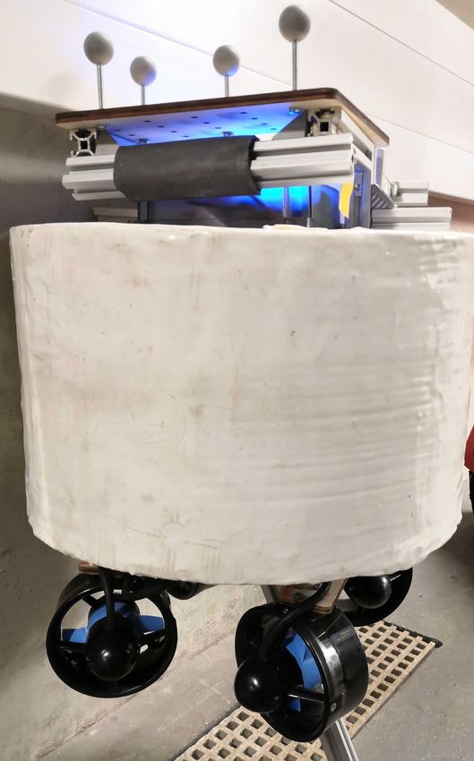
waves[i][ j].phase ← ε vehicle, SMARTY, in a towing tank capable of generating
j ← j+1 waves. SMARTY has a cylindrical shape and is equipped
end for with four thrusters. The Fig. 1 shows its top view, side
i ← i+1 view and thruster configuration. The physical specifications
end for of SMARTY are given in Table I.
TABLE I
ocean surface, Fw , is computed as the sum of the Froude- P HYSICAL PARAMETERS OF THE SMARTY PLATFORM .
Krylov force due to each component wave Fwi : Parameter Value
Diameter 0.32 m
Fw = ∑ Fwi . (10) Height 0.21 m
i Draught 0.11 m
Fwi is computed by integrating the product of wave pressure Mass 8.4 Kg
Thrusters BlueRobotics T100 Thruster [20]
with the wetted hull surface area, dS, as:
I
Fwi = pi (z)dS . (11) To investigate vehicle motion trends, we simulated
S SMARTY to move forward for 50 m in an open sea,
pi (z) is the wave pressure at depth z, defined as: while varying each of significant wave heights and wave
headings in separate and independent experiments. The
pi (z) = ρgekz cos[k(x sin µ + y cos µ) − ωei t] , (12) significant wave heights (in m), and wave headings were
where ωe is the encountered wave frequency and is computed of {0.5, 0.625, 0.75 . . . 2.0} and {0◦ , 11.25◦ , 22.5◦ . . . 360◦ },
as: respectively. Experiment were replicated 100 times with
ω2 different random seed values. Therefore, in total, 42900
ωe = ω − U cos(µ − φ ) . (13) (13 significant wave heights × 33 wave headings × 100
gtime is the time taken for the vehicle dynamics in the real
world and simulation time is the time taken to complete the
same dynamics in simulation.
The two key variables that influence the performance
of ASV-Swarm are the number of wave components used
to generate the irregular sea surface, and the size of the
simulated swarm. To assess the impact of these variables,
the forward motion experiment of the SMARTY platform
(b) Top view. was repeated1 .
In the first set of experiments, with a single vehicle, the
number of wave components was varied to observe its effect
on performance (see Table II). It is expected that a higher
number of component waves while costly to simulate, model
a more realistic sea-surface with better short-crested waves.
Our results indicate that ASV-Swarm is capable of providing
a high performance even with a larger number of component
waves than recommended (75 wave components with 15
(a) Side view. frequency bands per wave direction, see [18], p.13).
(c) Configuration of four In a second set of experiments, the performance of the
thrusters.
simulator was tested by simulating marine vehicle swarms of
Fig. 1. Illustration of the SMARTY platform simulated. varying size, while fixing the number of wave components
at 75 (see Table III). Results indicate that ASV-Swarm was
able to simulate 10 vehicles at 220x faster than real time,
replicates) experiments were performed. In each experiment, with the performance reducing to a two-fold speed-up for
forward motion was generated by applying a constant force very large swarms of 1000 vehicles.
of 1 N to each of the four thrusters, while constraining yaw
motion to achieve a constant wave heading. The vehicle was TABLE II
simulated with a fixed time step size of 40 ms. In each RUN - TIME PERFORMANCE OF SIMULATOR FOR DIFFERENT NUMBER OF
experiment, the 6 DoF position of the vehicle at each time REGULAR WAVE COMPONENTS OF THE IRREGULAR SEA SURFACE . T IME
step was recorded. STEP SIZE FIXED AT 40 MS .
Fig. 2 shows the vehicle motion trends observed by plot-
ting the mean of significant motion amplitudes for each trial. Component wave count Performance
(wave directions × frequency bands) (real time / simulation time)
The heave motion of the vehicle increases with an increase 15 (3 × 5) 2290x
in wave height. However, the roll and pitch amplitude at 30 (3 × 10) 1200x
first increases with an increase in wave height and then 75 (5 × 15) 467x
135 (9 × 15) 244x
decreases; this is because as the sea state increases from 195 (13 × 15) 178x
calm to high, the spectral peak of the ocean waves moves 260 (13 × 20) 142x
towards a lower frequency. The waves become higher but
also longer, making the waves less steep. The heave motion
does not show any correlation with the wave heading due to TABLE III
the circular waterline of the SMARTY platform. By contrast, RUN - TIME PERFORMANCE OF SIMULATOR FOR SIMULATION OF A
the roll and pitch motions show a strong correlation with the SWARM OF MARINE SURFACE VEHICLES . T IME STEP SIZE FIXED AT 40
wave heading. The pitch motion is highest in the head sea MS . I RREGULAR SEA SURFACE MODELLED USING A LINEAR
condition (wave heading at 180◦ ), followed by the following COMBINATION OF 75 REGULAR WAVE COMPONENTS .
sea condition (wave heading at 0◦ or 360◦ ) and lowest in the
beam sea condition (wave heading at 90◦ or 270◦ ). The roll Swarm size Performance
(real time / simulation time)
motion is highest in the beam sea condition and lowest in the 10 220x
head sea and following sea condition. These motion trends 50 50x
of the simulated vessel are in line with motions observed on 100 23x
150 15x
a seagoing vessel and assert the validity of the ASV-Swarm 200 12x
simulator. 250 9x
500 5x
B. Analysis of performance of ASV-Swarm 1000 2x
Experiments were also performed to estimate the perfor-
mance of the ASV-Swarm simulator. Performance is mea-
sured as the time required for completing the simulation and 1 Experiments were performed on an Intel Core i7-6700 CPU with 16GB
is expressed as the ratio of real time to simulation time. Real of DDR4 2133MHz RAM.(a) Heave motion trends. (b) Pitch motion trends. (c) Roll motion trends.
Fig. 2. Simulated motion trends of SMARTY in an open sea for 13 different significant wave heights and 33 different wave heading angles, averaged
over 100 replicates. A wave heading of 180◦ corresponds to a head sea condition.
V. C ONCLUSION AND FUTURE WORKS [4] H. Niu, Y. Lu, A. Savvaris, and A. Tsourdos, “An energy-efficient path
planning algorithm for unmanned surface vehicles,” Ocean Engineer-
ASV-Swarm is a simulator that models realistic ocean ing, vol. 161, pp. 308–321, 2018.
waves for a given sea state and the dynamics of surface [5] R. Mendonça, P. Santana, F. Marques, A. Lourenço, J. Silva, and
vehicles in the waves. Its use of frequency domain analysis J. Barata, “Kelpie: A ROS-based multi-robot simulator for water
surface and aerial vehicles,” in 2013 IEEE International Conference
and its two-phase computational structure allow a high run- on Systems, Man, and Cybernetics. IEEE, 2013, pp. 3645–3650.
time performance even with many component waves and [6] M. Paravisi, D. H Santos, V. Jorge, G. Heck, L. M. Gonçalves,
large swarm sizes. ASV-Swarm is implemented based on and A. Amory, “Unmanned surface vehicle simulator with realistic
environmental disturbances,” Sensors, vol. 19, no. 5, p. 1068, 2019.
the assumption that the irregular sea surface is composed [7] A. Thakur and S. K. Gupta, “Real-time dynamics simulation of
of many regular waves and the net wave force at any instant unmanned sea surface vehicle for virtual environments,” Journal of
of time is a linear summation of wave force due to each Computing and Information Science in Engineering, vol. 11, no. 3, p.
031005, 2011.
component wave. Also, the wave pressure variation along [8] M. Prats, J. Perez, J. J. Fernández, and P. J. Sanz, “An open source tool
the hull is approximated as linear due to the relatively for simulation and supervision of underwater intervention missions,”
small size of ASVs used in marine swarms with respect in 2012 IEEE/RSJ International Conference on Intelligent Robots and
Systems. IEEE, 2012, pp. 2577–2582.
to the wavelengths. These assumptions hold for most use [9] M. M. M. Manhães, S. A. Scherer, M. Voss, L. R. Douat, and
cases of current ASVs, which are slow-moving vehicles T. Rauschenbach, “UUV simulator: A gazebo-based package for un-
operating predominantly in mild sea conditions. High-speed derwater intervention and multi-robot simulation,” in OCEANS 2016-
MTS/IEEE Monterey. IEEE, 2016, pp. 1–8.
simulation with high fidelity of non-linear systems, such as [10] N. Koenig and A. Howard, “Design and use paradigms for gazebo, an
the dynamics of a high-speed planning craft or environments open-source multi-robot simulator,” in 2004 IEEE/RSJ International
with wave breaking, is currently not possible with ASV- Conference on Intelligent Robots and Systems (IROS)(IEEE Cat. No.
04CH37566), vol. 3. IEEE, 2004, pp. 2149–2154.
Swarm but may be achieved in future work by combining it [11] M. Quigley, K. Conley, B. Gerkey, J. Faust, T. Foote, J. Leibs,
with computational fluid dynamics (CFD) based approaches. R. Wheeler, and A. Y. Ng, “Ros: an open-source robot operating
system,” in ICRA workshop on open source software, vol. 3, no. 3.2.
VI. S UPPLEMENTARY INFORMATION Kobe, Japan, 2009, p. 5.
[12] T. Tosik and E. Maehle, “MARS: A simulation environment for marine
The simulator is publicly available as open source at robotics,” in OCEANS 2014-St. John’s. IEEE, 2014, pp. 1–7.
https://github.com/resilient-swarms/asv-swarm.git. [13] J. Fréchot, “Realistic simulation of ocean surface using wave spectra,”
in Proceedings of the First International Conference on Computer
VII. ACKNOWLEDGEMENT Graphics Theory and Applications (GRAPP 2006), Portugal,
2006, pp. 76–83. [Online]. Available: https://hal.archives-ouvertes.fr/
The remote-operated vehicle, SMARTY, and the towing hal-00307938
tank facility are part of the Department of Civil, Maritime [14] S. Thon and D. Ghazanfarpour, “Ocean waves synthesis and animation
and Environmental Engineering at University of Southamp- using real world information,” Computers & Graphics, vol. 26, no. 1,
pp. 99–108, 2002.
ton, United Kingdom, and the authors would like to thank [15] Modelling and analysis of marine operations, DNVGL-RP-N103.
Dr Blair Thornton and his team of researchers for providing DNV-GL, 2017.
SMARTY data for validating the simulator. [16] T. I. Fossen, Handbook of marine craft hydrodynamics and motion
control. John Wiley & Sons, 2011.
R EFERENCES [17] C. Stansberg, G. Contento, S. W. Hong, M. Irani, S. Ishida, R. Mercier,
Y. Wang, J. Wolfram, J. Chaplin, and D. Kriebel, “The specialist
[1] E. Şahin, “Swarm robotics: From sources of inspiration to domains committee on waves final report and recommendations to the 23rd
of application,” in Swarm Robotics, E. Şahin and W. M. Spears, Eds. ittc,” Proceedings of the 23rd ITTC, vol. 2, pp. 505–551, 2002.
Berlin, Heidelberg: Springer Berlin Heidelberg, 2005, pp. 10–20. [18] E. V. Lewis, “Principles of naval architecture second revision,” Jersey:
[2] M. Brambilla, E. Ferrante, M. Birattari, and M. Dorigo, “Swarm SNAME, vol. 2, 1988.
robotics: a review from the swarm engineering perspective,” Swarm [19] O. F. Hughes and J. K. Paik, Ship structural analysis and design. The
Intelligence, vol. 7, no. 1, 2013. Society of Naval Architects and Marine Engineers, 2010.
[3] M. Duarte et al., “Application of swarm robotics systems to marine [20] “BlueRobotics T100 Thruster,” https://bluerobotics.com/store/
environmental monitoring,” in OCEANS 2016-Shanghai. IEEE, 2016, thrusters/t100-t200-thrusters/t100-thruster/, accessed: 2020-02-14.
pp. 1–8.You can also read