Electric Field Stress Control on FGM Spacer with Particle in a Three-Phase GIS Using Metal Inserts for Sustainable Agriculture
←
→
Page content transcription
If your browser does not render page correctly, please read the page content below
Electric Field Stress Control on FGM Spacer with Particle in a Three-Phase GIS
                 Using Metal Inserts for Sustainable Agriculture

    Yogesh Sambhana1; Sravana Kumar Bali 2; V.S. Polamraju. Sobhan3; G.V. Nagesh Kumar4
                     1
                         Vignan’s Institute of Information Technology, Visakhapatnam.
                                        1
                                          yogesh.sambhana@gmail.com
                              2
                                Gitam Deemed to beUniversity, Visakhapatnam.
                                             2
                                               sravanbali@gmail.com
                                3
                                  VFSTR Deemed to be University, Vadlamudi.
                                            3
                                              pvssobhan@gmail.com
                                                4
                                                  JNTU, Pulivendula.
                                              4
                                                drgvnk14@gmail.com

Abstract
Recently, this kind of agriculture is in danger of threatening its future since it depends upon
industrial agriculture to provide the bulk of the food we eat. In high-voltage applications, the three-
phase Gas Insulated Busductor (GIB) is considered to be the most important to fulfill high demand.
Due to numerous flaws like as delamination, protrusion, etc. induced during the switching process,
GIB is shown to have insulator failures. Those flaws have a significant impact upon the distribution
of the electric field across the distance and hence on the entire GIB system, which causes enormous
economic losses. This paper provides a post-type spacer for a three-phase GIB of delamination with
a Functionally Degraded Material (FGM), an additional particle introduced at high voltage for the
analysis of the adverse behavior of the spacer and subsequent insertion of metal inserts minimize the
stress of the electronic field. By doping it with varying permittivity values to provide uniform electric
field stress using a Finite element procedure, FGM is spatially dispersed with various filling
materials. Simulation with planned spacer is performed as faults at various voltages and FGM
grades with delamination and particle. With the insertion of the metal insert in the FGM spacer type
postal insert, the influence of aluminum particles with varying delamination sizes is reduced and the
findings obtained are given.

Key-words: Gas Insulated Busductor (GIB), Functionally Degraded Material (FGM), Electric Field.

ISSN: 2237-0722                                                                                        1
Vol. 11 No. 4 (2021)
Received: 17.01.2021 – Accepted: 28.05.2021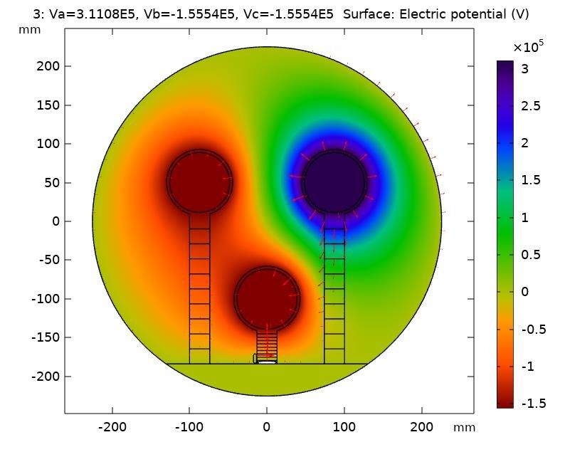
1. Introduction

        Whilst industrialized agriculture has succeeded in generating enormous amounts of food in
the present day, due to agricultural issues the future of food production is at risk. The loss of farm
land and the reduction in crop and livestock production are two of the most important challenges in
agriculture. Gas Insulated Busduct (GIB) is wield in applications of large voltages because it serves
important loads which are required for the satisfaction of high demand for electricity and public
safety. The substations are ideally built to prevent natural disasters, such as environmental changes,
inundations and so on. Although GIB is efficient than standard substations, they suffer few problems
mostly due to spacer failures. Due to various flaws such as parcel contamination, protrusion, vacuum,
depression, delamination etc., the isolating spacers lose their dielectric strength and therefore a proper
technique for reducing electrical stress in the field must be applied.
        Several researchers [2,3] have identified alternative to spacer design approaches, which can
increase the reliability of GIS isolators by use of aluminum oxide (Al2O3) along with epoxy
materials with functionally grading M, in literature, in order to study electric field stress in GIB and
UHVAC gas isolated lines that play a vital role in the optimal allocation of energy. However, before
they are applied in industry, there are further problems for manufacturing, design and the evaluation
of FGM performance.With the use of centrifugal forces, few modes of growing and reducing can be
achieved; a flexible manufacturing technique for FGM insulators is needed. It is found that the main
source of electron emission was TJ, and found that the field stress was decreased by adding metal
inserts to the interlocker with multifault flaws. Many investigated that the GIS compactness, electric
field stress reduction technique is utilised to grade the plain epoxy length by using FEM analysis to
varied permittivity values.The surface flashover in a cone-type spacer for GIS was examined in [6]. It
was shown that it may be lowered by either a FGM spacer by putting the metal inserts at the triple
point intersection; GIB. Several authors found that the failure of Spacer is one of the causes of the
breakdown in dielectric power that generates surface flashing in GIS []. However, on the spacer
surface there are numerous additional flaws like as delamination, fractures, particles, vacuums etc.
However, this negative impact leads to GIB failure, and must thus be managed. It is observed that the
voltage-time disruption of epoxy isolators including three micro-defect types (cracker, void,
delamination, metal particles) was investigated and found that the apparent PD for GIS spacers is
almost equal to 1 PC while those effects can be reduced by the use of metal inserts. Several
researchers[10,11] have observed that ultrahigh-frequency (UHF) partial dissipation is the primary

ISSN: 2237-0722                                                                                         2
Vol. 11 No. 4 (2021)
Received: 17.01.2021 – Accepted: 28.05.2021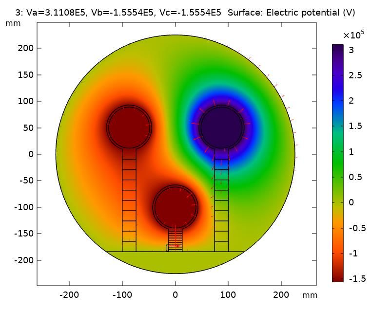
reason for GIS failure caused by a number of defects and diversified optical sensing methods
developed over the last couple of years because of highly sensitive and anti-electromagnetic
interference that can be addressed through employees UHF external measuring system of the antenna
sensor together with various techniques to gather PD signals from the GIS equipment. Jagadeesh
Adari et.al[12] investigated how a cone type spacer may achieve fields within allowable values by
utilizing three various types of FGM GIS methods, nevertheless, a post type GIB spacer can be
extended. However, by adopting a new approach, i.e. by placing Metal Insert on the necessary place,
the impact of the particle may be minimized. The dielectrical properties of the metallic particle in the
type cone spacer were evaluated [21], which was better than disc type in the suggested FGM grading.
The study can be done for FGM postal systems but, with metal inserts the spacing can be decreased.
The purpose of this work is to examine the E F Stress at TJ close to the box end in the 3-ϕ Gas
Isolated Busduct with a FGM post interval of various types of grading. For electrical field stress at
the enclosure end near the FGM spacer TJ, the insulation properties have been studied. The
distribution of the Electrical Field Stress created by delaminating the FGM post-type intersection at
the threefold junction is calculated. The EF stress in the triple junction of the cage end is analyzed,
and the worsening of this stress can be reduced by inserting a recessed metal at the end of the cable
with both faults together, for three different ranges of permissiveness values, types of FGM grades in
TJ Y conductor, and for those two faults.
2. Modelling of 3- Phase GIB
Many scientists used two primary electronic equations, that is, the Laplace equation and
Poisson equation with the limits of the supposed domain, to compute the electric field. These
analytical or numerical procedures are solved using two ways. Three-phase GIB operates on high
voltages, thus it is very difficult to analyze the equation of Laplace and the Poisson equation.
Therefore, numerical approaches are employed in electrical field calculation to reduce this issue. The
techniques are divided into the FDM, the FEM, the Charge Simulation Method (CSM) and the Border
Elements Method (BEM). Although the preceding approaches have advantages and limitations, FEM
is more adequate for tackling complicated questions. The electric field intensity "E" may be measured
in a GIB tri-phase utilizing Poison Equation with the border condition of both spacer electrodes.
E = −V (1)
where, V is the capacity on the volt spacer.
From divergence theorem
ISSN: 2237-0722 3
Vol. 11 No. 4 (2021)
Received: 07.05.2021 – Accepted: 28.05.2021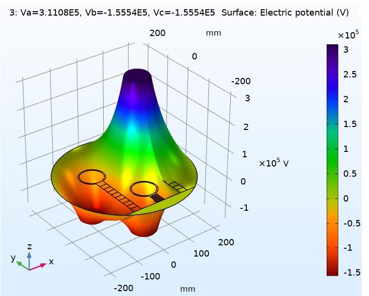
.D = v
(2)
The connection between the density of the flux and the intensity of the electrical field is
described by,
D = E (3)
where = o r is insulating material permittivity.
Substituting equ (3) and equation (1) in equation (2),
.E = v (4)
then , . (− V ) = v (5)
The equation (5) is reduced into the equation of Poisson by equation,
− v
2V = (6)
When the load is supposed to be evenly distributed, the volume load density is zero, and so
Equation (6) may be reduced as an equation of Laplace (7)
2V = 0 (7)
So, the boundaris of the HV conductors in 3-ph GIB and the ground enclosure are represented
in Figure 1 with the specifications as follows: The applied potential, at the HV Conductor at three
ranges are, VR(rms) = 72.5KV,132KV,220KV and Potential of Enclosure = 0V
Fig. 1 - Boundary Conditions 3-ϕ GIB
ISSN: 2237-0722 4
Vol. 11 No. 4 (2021)
Received: 07.05.2021 – Accepted: 28.05.2021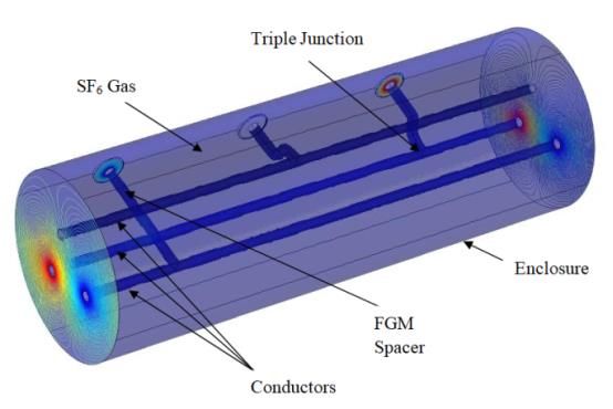
Consider, VR , VY & VB are the voltages at the three conductors R,Y,B w.r.t. ground at V=0
volts, and let rR, rY, rB, r are the radius of each conductor and R , Y , B are their line charge
densities. For a 3-ϕ GIB with three equidistant conductors, the voltage is given by
d d d BR YB d RY d YB d BR BR d RY d YB d BR
V = RY ln RY YB + ln + ln (8)
6 O r3 6 O r3 6 O r3
let d RY = d YB = d BR = d ,
where dRY, dYB and dBR are the distance between each conductor in a 3-ϕ GIB.
d
ln r
2
V =
2 RY + YB + BR = 0 (9)
2 O
The electrical field intensity for a 3-ϕsystem is obtained from the FEM analytical idea
→ V → V →
E= i+ j (10)
x y
→ d RY d YB d BR → d RY d YB d BR →
E=−
1
ln + + i + ln + +
BR j (11)
6 O x y
RY YB BR RY YB
r3 r3
By utilizing FEM analysis, the energy stored in the full volume 'v' of the area, under
continuous electro statics of constant dialectic strength (12).
W =
1
2
(
2V dv ) (12)
In addition, the dielectric material is assumed an isotropic and the potential distribution does
not vary in direction z, therefore the consideration is taken of a two dimensional Cartesian system.
Hence In this comparable region, the total stored energy is provided by equation (18) which may be
expressed from the equation (12).
1 2V 2V
2
W= + dv (13)
x 2 y 2
x y
The energy density for a small area (dxdy) is given by
W 1 2V 2V
= +
dxdy (14)
2 x 2 y 2
x y
z
where x and y are the dielectric constants in the respective parameters of x, y. By
substituting Laplace’s Equation in equation (12), the equation is simplified to
ISSN: 2237-0722 5
Vol. 11 No. 4 (2021)
Received: 07.05.2021 – Accepted: 28.05.2021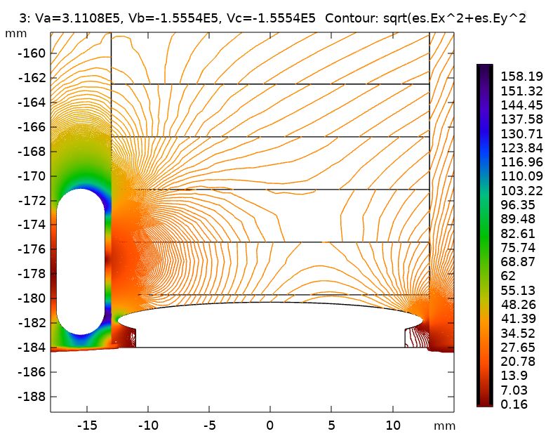
dW =
1
2
( )
2V dxdy = 0 (15)
dW = 0 (16)
Hence from the equation (16), the change in electrostatic energy stored is zero as the potential
difference is constant inside the studied domain.
W W W
dW = dV1 + dV2 + ............ + dVn = 0 (17)
V1 V2 Vn
The above equation (14) can be written as below
dV1
W W .....
....... =0 (18)
V1 Vn .....
dVm
where ‘n’ and ‘m’ are number of unknown potential nodes and triangles considered in mesh
of a three phase GIB.
dW
To reduce electrostatic energy function, the parameters of must be equal to zero.
dV
W W
i.e. ....... =0 (19)
V1 Vn
3. Functionally Graded Material Post Type Spacer
A novel approach for the creation of a post-type distance in the 3-ϕ GIB proposal is the
functional classification of materials to produce a unitary field distribution over its length. The FGM-
Post type spacers are graded using several techniques, such as |-FGM, −-FGM, (diagram/-)-FGM and
the method of change of frequency, {i.e.} In this article the author of three sorts of degree, like GL-
FGM, GH-FGM & GU-FGM, is picked out of all the aforementioned techniques. Centrifugal casting
and 3D printing can be used to produce the FGM. 3D-Printing is a new technology involving the
production process at the bottom. The following layers or parts of material are collected to produce
3D objects in computer control, whereas in Centrifugal casting the technique is applied from top to
bottom. Figure 2 shows the manufacture of GL- FGM. In this article, for the three forms of
classification, three alternative permittivity ranges are studied as follows. The FGM grading
ISSN: 2237-0722 6
Vol. 11 No. 4 (2021)
Received: 07.05.2021 – Accepted: 28.05.2021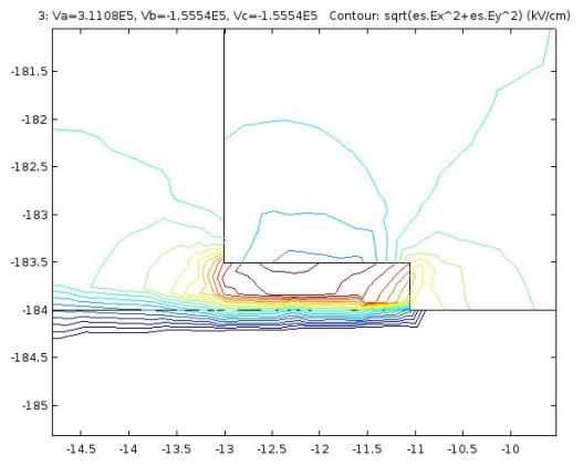
categories with allowability values of various situations from Table 1. For the Table, for the
permittivity fluctuation of example 1 for various FGM gradings is illustrated in Figure 3.

                                Fig. 2. Flow chart of fabrication of GL-FGM

                                 Table 1 - Permittivity Values of Gradings
                           Permittivity Ranges
           Grading Type
                           Case1                    Case 2                     Case 3
           GL-FGM          3.950 - 3.50             4.050 - 3.60               4.150 - 3.70
           GH-FGM          3.50 - 3.950             3.60 - 4.050               3.70 - 4.150
           GU-FGM          3.950 -3.50 - 3.950      4.050 - 3.60 - 4.050       4.150 - 3.70 - 4.150

                            Fig. 3 - Permittivity Variation of Gradings for Case 1

ISSN: 2237-0722                                                                                       7
Vol. 11 No. 4 (2021)
Received: 07.05.2021 – Accepted: 28.05.2021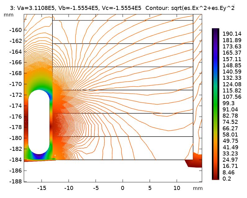
The FGM spacer is constructed with 10 identical grades of the same height and breadth of the
three conductors. The grading takes place in three types of FGM method with various permittivity
ranges

4. Delamination Impact on FGM Post Type Spacer

         Delamination is one of the primary spacer defects that generates a distance between the
spacers and the ends of the enclosure that is produced owing to unanticipated internal or external
pressures such as mechanical stress, thermal stress and vibration during the GIB operating process.
Delamination occurs as the most severe fault in the FGM after the distance between a three-stage gas
insulated bus pipeline. The Electric Field the stress of the spacer is calculated on a GIB three-phase
spacer (FGM Post type spacer) with dimensions Dw = 1.950 mm, Dh = 0.50 mm, Gw = 4.30 mm.

                           Fig. 4 - Representation of Delamination on Conductor Y

5. Effect of Particle adhering to FGM Post Type Spacer

         Another important flaw in GIB's operation is the existence of metallic particles. During the
production process, particles are generally generated by switching other switch disconnectors from
circuit breakers or mechanic vibrations from heat. Particles generally come in many forms, such as
spherical, elliptical or filamentary in various sizes. Most of these particles are detected within the
box, on the conductor, or on the distance between the gaseous bus conduit. The presence of leading
particles has a greater influence on the FGM than isolating particles because isolating particles don't
lower collapse voltage if they just gain a charge and, as a result, larger particles have a greater effect
than smaller particles. The electric field stress in the spacer must be calculated to understand the
behaviour of the particles on the FGM post-spacer. As free particles are most hazardous compared to
moving particles, free particles are taken as indicated in figure 5 for study of the FGM Post type

ISSN: 2237-0722                                                                                         8
Vol. 11 No. 4 (2021)
Received: 07.05.2021 – Accepted: 28.05.2021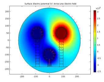
spacer in a GIB 3-ϕ. Here the particle is produced near the Driver Y TJ as compared to Driver R and
Driver B it develops an electrical field stress. From the previous explanation, as the particle may have
different materials, an investigation of three particles such as aluminum, copper and silver is carried
out. The "Al" particle is seen to produce more electrical stress than the other two materials. The
elliptical "Al" particle is regarded as 4mm wide with a circular edge radius of 8mm in height and
2mm round.

                           Fig. 5 - Particle Clinging to the FGM Spacer in the GIB

6. Results and Discussions

        The fundamental modeling of a 3-ϕ GIB with a 225.50mm radius of the shared enclosure bus
duct without delamination. The 3-ϕ GIB has a relatively primitive capacity of 1.00150 for SF6 gas.
All three R, Y and B conductors are inside the same enclosure and positioned on the corners of a
38.660 mm equilateral triangle. The distance between driver R and the end of a box is 193.80 mm.
The spacing distances are assumed as 43 mm and 193.80 mm from conductors Y to the of enclosure
end, and the width of each spacer as 26 mm. FEM using epoxy/alumina composite as a spacer and
three conductive systems located at the equidistance between each other, shielding the ball, the
shielding ring and SF6 is a simulation of the 3-ϕ model in Figure 6.

ISSN: 2237-0722                                                                                       9
Vol. 11 No. 4 (2021)
Received: 07.05.2021 – Accepted: 28.05.2021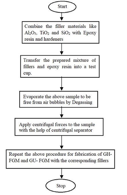
Fig. 6 - Design Model of Three Phase GIB in 3D Cartesian System
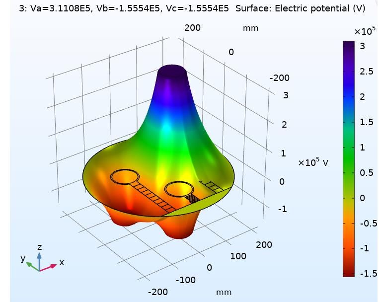
All the three R, Y & B conductors are positioned within the shared enclosed GIB at an
equidistance from each other in the suggested simulation model. The Dirigent R is applied to RMS
voltages of 72.5 kV, 132 k V and 220 kV, and with phase shift of –1200& to +1200, respectively, the
voltages of the Dirigent VY & VB. The external electrode is zero voltage, i.e. the end of the box. The
corresponding maximum voltages of driver R, Y, B are presented in Table 2 for these RMS voltages.
The three-phase GIB has a relatively permittive capacity of 1.00150 for SF6 gas.
Table 2 - Maximum Voltages of Conductor R,Y,B
RMS Voltage VR max VY max VB max
(kV) (kV) (kV) (kV)
V1= 72.50 102.5150 -51.2580 -51.2580
V2= 132.00 186.650 -93.3240 -93.3240
V3= 220.00 311.080 -155.540 -155.540
Table 3 - Different Widths, Heights of Delamination
Width(mm) Height(mm) V1=72.5KV V2=132KV V3=200KV
1.46 0.129 0.234 0.391
1.95 mm 1 0.135 0.247 0.411
0.5 0.149 0.271 0.453
1.46 0.1205 0.219 0.365
1 mm 1 0.124 0.225 0.376
0.5 0.136 0.248 0.413
1.46 0.112 0.203 0.339
0.5 mm 1 0.116 0.211 0.352
0.5 0.124 0.225 0.375
From table 3, Electrical field stress decreases by 1.950 mm, 1 mm & 0.50 mm, with a height
reduction i.e. by 1.460 mm, 1.00mm & 0.50 mm, while the electrical field stress decreases. The width
ISSN: 2237-0722 10
Vol. 11 No. 4 (2021)
Received: 07.05.2021 – Accepted: 28.05.2021(Dw) of 1.950 mm and height (Dh) of 0.50 mm, which is the greatest electric field stress. Therefore,
for further study of the spacers in this three-phased GIB design this dimension (1.950mm X 0.50mm)
has been shown in figure 6.
Table 4 represents, TJ's simulated electrical field stress results vary along with Al, Cu and Ag
particles, along with delamination at varied operating voltage, with different types of particles. Table
4 shows that, compared with Cu and Ag, the electric field stress in all operating voltages for the
particle formed of Al is large. Therefore, for further study of the spacers in that triphasic GIB design
as seen in figure 7, the Al-particle with the above-mentioned delamination dimension is chosen.
Table 4 - Difference of Particles Together with Delamination Due to Electrical Field Stress
Type of Particle 72.50kV 132.0kV 220.0kV
Al 1.62310 0.29440 0.49110
Cu 1.622650 0.293980 0.490650
Ag 1.622550 0.29390 0.490550
Figure 7 shows 3-ϕ GIB design charts using the prior delamination dimensions and the FGM
post type particle with MI. A metal insert (MI) with multiple shapes and dimensions and a
corresponding MI with the form (i.e. the blending of rectangles and elliptic) with the dimensions of
the rectangle as wide and height (22 mm X 1.50 mm) and ellipse with the length of the axis and b
axis of (12.50 mm X 1.50 mm) was observed to help reduce the effect from delamination and the
particular impact of FGM spacers.
Fig. 7 - FGM Post-type Spacer with Microdefect Delamination and MI
ISSN: 2237-0722 11
Vol. 11 No. 4 (2021)
Received: 07.05.2021 – Accepted: 28.05.2021For above FGM Post type spacer with delamination led to a large electric field stress at TJ at
the end of conductor Y, as seen in Figure 8, thus just for the conductor Y, the simulation is performed
and tabled in Table 5. The Electric Field Stress of conductor Y for case 3 of GL- FGM is found in
Table 5 in comparison with other GH FGM and GU FGM grades.
Table 5 - Delamination Electric Field Stress
Delamination Electric Field Stress at TJ without MI in KV/cm
Type Permittivity values
V1= 72.50KV V2=132.0 KV V3= 220.0 KV
Case1 0.160 0.29120 0.4850
GL-FGM Case 2 0.1610 0.2930 0.4880
Case 3 0.16170 0.29430 0.49040
Case1 0.14760 0.26880 0.4480
GH-FGM Case 2 0.14860 0.27060 0.4510
Case 3 0.14960 0.27230 0.45380
Case1 0.15020 0.27360 0.4560
GU-FGM Case 2 0.150350 0.27370 0.45620
Case 3 0.15120 0.27540 0.45890
Figure 8 shows that the magnitude of Electric field stress at the enclosure i.e. at TJ due to
delamination is high, which is clearly observed that the value from Figure 9, the electric field stress at
TJ is 0.1617,0.2943 and 0.4904 kV/cm at V1= 72.5 kV, V2=132 kV and V3= 220KV respectively.
The surface plot and the Quiver plots of the designed FGM spacers with delamination at conductor Y
are as shown in figure 10 and figure 11 respectively. The red colour in both figures is representing
high electric field stress at conductor VA due to its high potential and the blue colour is indicating
high electric field stress which is observed at the TJ of enclosure ends. Figure 12, figure 13 represents
Quiver plot and Contour Plot of conductor Y for FGM post type spacer with delamination with high
electric field stress at the Triple Junction. Similarly, the electric field stress in the designed
delaminated FGM Post type spacers can be seen from the Mesh plot. The thickness or congestion of
the mesh triangles is indicating that the field is high due to its curved shape as shown in figure 14 and
figure 15.
Another frequent fault is metallic particles, which is causable by many procedures, leading to
Spacers failure and simulating the impact of the electrical field distribution of the post-type FGM
spacer with delamination and the particulate matter. The planned FGM Post type distortion with
delamination and particulate matter caused significant electrical field stress at TJ at the end of
container Y and so simulation for conductor Y alone is carried and is shown in Table 6. A MI is
ISSN: 2237-0722 12
Vol. 11 No. 4 (2021)
Received: 07.05.2021 – Accepted: 28.05.2021integrated into the TJ of a box of the same conductor, as shown in figure 7, to create uniform electric
field distribution across the spacer of conductor Y.
In table 6, a maximum reduction of 80.870 percent of EF stress on the TJ's of the box end is
observed after MI has been inserted on conductor Y for case 3 of the GL-FGM grading of 220.0KV
of operating voltage; in case 3 of GH FGM the decrease is 81.900 percent on 72.50KV and in case 3
of GU FGM the decrease is noted as 81.930 percent on the 72.50k V case 3 when the decrease is
noted as 81.930 percent. Figures 16 and 17 show that the electric field stress is decreased at 72.50 kV,
132 .0KV and 200.0KV correspondingly from 0.20450 to 0.03920 k V/cm, 0.3730 to 0.07150 kV/cm
and 0.6220 to 0.1190 kV/cm.
Figure 18 shows the surface graph of the FGM Delamination and Particle post-style spacer
and the matching height surface graphs are as given in Figure 20. In the future, stress is reduced by
utilizing the MI near TJ as illustrated in Figure 19 with the appropriate surface plots with a height
after inserting the MI. The green color represents electrical field stress at Driver Y which is seen at
the extremities of the container to minimize this impact at TJ Enclosure ends in Figure 19 are inserted
MI's. Figures 20 and 21 show the contour plot of conductor Y to FGM post-type delaminated and
high electrical field stress and MI EF stress reduction spacers, respectively. Figures 20 and 21
indicate. In the developed FGM post-type spacers, the EF stress can also be observed in the mesh plot
owing to particle without and with MI. The mesh triangles are demonstrated to be of large thickness
or congestion owing to their curved shape as illustrated in figures 22 and 23. The fundamental aim of
the mesh plot is to define rather than a uniform color the qualities of the plot piece. Mesh plot
combines diverse data sets for various plots to create the most interesting outcomes in a group of the
single plot.
Fig. 8 - Effect of Delamination on FGM Post Type Spacer
ISSN: 2237-0722 13
Vol. 11 No. 4 (2021)
Received: 07.05.2021 – Accepted: 28.05.2021Fig. 9 - Zoomed Plot of FGM Post Type Spacer with Delamination
Fig. 10 - Surface Plot of FGM Post Type Spacer with Delamination
Fig. 11 - Quiver Plot- FGM Post Type Spacer with Delamination
ISSN: 2237-0722 14
Vol. 11 No. 4 (2021)
Received: 07.05.2021 – Accepted: 28.05.2021Fig. 12 - Quiver Plot- FGM Post Type Spacer with Delamination
Fig.13 - Contour Plot- FGM Post type Spacer with delamination
Fig. 14 - Mesh Plot of FGM Post Type Spacer with Delamination
ISSN: 2237-0722 15
Vol. 11 No. 4 (2021)
Received: 07.05.2021 – Accepted: 28.05.2021Fig. 15 - Spectrum Mesh Plot of FGM Post Type Spacer with Delamination
Table 6 - Delamination Electric Field Stress with Particle
% Reduction of
Delamination Electric field Delamination Electric field
Delamination Electric
stress and Particle at TJ stress and Particle at TJ with
field stress and Particle at
devoid of MI in KV/cm MI in KV/cm
Type Permittivity TJ due to MI
V2= V3= V2= V3= V2= V 3=
V1= V1= V1=
132.0 220.0 132.0 220.0 132.0 220.0
72.50KV 72.50KV 72.50KV
KV KV KV KV KV KV
Case1 0.2042 0.3725 0.62 0.04023 0.0735 0.1225 80.30 80.27 80.24
GL-
Case 2 0.2044 0.3727 0.62175 0.0397 0.0722 0.1208 80.58 80.63 80.57
FGM
Case 3 0.2045 0.373 0.6222 0.0392 0.0715 0.119 80.83 80.83 80.87
Case1 0.186 0.339 0.5654 0.0346 0.063 0.1054 81.40 81.42 81.36
GH-
Case 2 0.1864 0.34 0.5668 0.0342 0.0624 0.1041 81.65 81.65 81.63
FGM
Case 3 0.1867 0.3406 0.568 0.0338 0.0617 0.1029 81.90 81.88 81.88
Case1 0.188 0.3427 0.5716 0.0349 0.0638 0.10645 81.44 81.38 81.38
GU-
Case 2 0.1884 0.3435 0.5728 0.0345 0.063 0.1052 81.69 81.66 81.63
FGM
Case 3 0.189 0.3441 0.574 0.03415 0.0623 0.104 81.93 81.89 81.88
Fig. 16 - Electric Field Characteristics of FGM Post Type Spacer which due to Delamination and Particle
ISSN: 2237-0722 16
Vol. 11 No. 4 (2021)
Received: 07.05.2021 – Accepted: 28.05.2021Fig. 17 - Reduced Electric Field Stress with Metal Insert at Enclosure End
Fig. 18 - Surface Plot of FGM Post Type Spacer with Particle
Fig. 19 - Surface Plot of FGM Post Type Spacer with Particle with Metal Insert
ISSN: 2237-0722 17
Vol. 11 No. 4 (2021)
Received: 07.05.2021 – Accepted: 28.05.2021Fig. 20 - Surface Plot with Height of FGM Post Type Spacer with Delamination and Particle
Fig. 21 - Surface Plot with Height of FGM Post type Spacer with Delamination and Particle with Metal Insert
Fig. 22 - Contour Plot- FGM Post Type Spacer with Particle
ISSN: 2237-0722 18
Vol. 11 No. 4 (2021)
Received: 07.05.2021 – Accepted: 28.05.2021Fig. 23 - Contour Plot- FGM Post type Spacer with Particle and Metal Insert
Fig. 24 - Mesh Plot of FGM Post Type Spacer with Delamination and Particle
Fig. 25 - Mesh Plot of FGM Post Type Spacer with Delamination and Particle and Metal Insert
ISSN: 2237-0722 19
Vol. 11 No. 4 (2021)
Received: 07.05.2021 – Accepted: 28.05.20217. Conclusion
This research analyzes how important the spacer in the three phase of GIB is for the FGM
postal spacer for a 3-ϕ GIB electrical fielding distribution. In order to analyze the severe defect of
delamination and particulates, the three distinct types of FGM grading with various permitivity
ranges are studied. It is seen that in comparison to all other conductors at different points the
maximum electrical field pressure is achieved at TJ of conductor Y. Major flaws like as delamination
and particulate matter are prevalent with high voltage GIB, so that different types of particles such as
aluminum, copper and silver are added here. In contrast to all R, Y, and B conductors as Driver Y,
TJ's enclosure end for the FGM after-type distortion has primarily high electric field stress, such that
both faults are created on the same Driver Y and their influence was diminished when the MI was
inserted at TJ in the space shell's end.The electronic field stress is considerable in case 3 of GL- FGM
compared with other cases and GH-FGM and GU FGM ratings for fault delamination at the TJ of
driver Y. The field is worsened significantly for the defect delamination alongside particle. It is
observed that the high electrical field stress is achieved by the graduation of Case 3 of the GL-fGM
and for Case 3 of the GU FGM by inserting a recessed metal insert in the TJ in the box end in the
three-phase GIB post-grade FGM spacer.
References
Shu. Y, Chen. W, “Research and application of UHV power transmission in China”, High Voltage,
Vol.3 (1), pp. 1-13, 2018.
Liang. H, Du. B, Li. J, Wan. Z, “Mechanical stress distribution and risk assessment of 110 kV GIS
insulator considering Al2O3 settlement”, High Voltage, Vol.4 (1), pp. 65-71, 2019.
Talaat, M., El-Zein, A., Amin, M., “Developed optimization technique used for the distribution of U-
shaped permittivity for cone type spacer in GIS”, Electric Power Systems Research, 163, 754-766,
2018.
Chakravorti. S, A. Lahiri, “Electrode-Spacer Contour Optimisation by ANN aided Genetic
Algorithm”, IEEE Trans. on Dielectrics and Electrical Insulation, 11(6), 964-975, 2004.
Naidu. Y.S, Kumar. G.V.N, “Minimisation of electric field stress at triple junction of a functionally
graded cone type spacer in a gas insulated busduct with metal inserts”, High Voltage, 2(2), 110-118,
2017.
Alan H. Cookson, “Review of high voltage gas breakdown and insulators in compressed gases”,
IEEE Proceedings on Physical Science, Meas. and Instr., Manag. and Edu., Vol. 128(4), 303–312,
1981.
Tanaka. H, Tanahashi. D, Baba. Y, Nagaoka. N, “Finite-difference time-domain simulation of partial
discharges in a gas insulated switchgear”, High Voltage, Vol.1(1), 52-56, 2016.
ISSN: 2237-0722 20
Vol. 11 No. 4 (2021)
Received: 07.05.2021 – Accepted: 28.05.2021Hong-Yang. Z, Guo-Ming. M, Wang. Y, Cheng-Rong. L, “Optical sensing in condition monitoring of gas insulated apparatus: A review”, High Voltage, 4(4), 259-270, 2019. Jagadeesh A, V.S.K. Rao Gadi, G.V.N. Kumar “Mitigation of field stress with metal inserts for cone type spacer in a gas insulated busduct under delamination”, Engineering Science and Technology, 21, 850-861, 2018. Maren Istad, Magne Runde “Thirty-Six Years of Service Experience with a National Population of Gas-Insulated Substations”, IEEE Trans. on Power Delivery, 25(4), 2448 – 2454, 2010. G.V.N Kumar, J. Amarnath, B.P. Singh, K.D. Srivastava, “Electric Field Effect on Metallic Particle Contamination in a Common Enclosure Gas Insulated Busduct”, IEEE Trans. on Dielec. and Elect. Insulation, 14(2), 334-340, 2007. G.V.N Kumar, J Amarnath, “Assessing the Risk of Failure due to Particle Contamination in GIS under various Coefficient of Restitutions”, Journal of Electrical Systems, 10(3), 331-343, 2014. Sun. J, Sun. L, Chen. W, Li. Z, Yan. X, Xu. Y, “Metal particle movement and distribution characteristics under AC voltage and ball-plane electrodes”, High Voltage, 4(2), 138-143, 2019. ISSN: 2237-0722 21 Vol. 11 No. 4 (2021) Received: 07.05.2021 – Accepted: 28.05.2021
You can also read