Direct observation of the effects of spin dependent momentum of light in optical tweezers
←
→
Page content transcription
If your browser does not render page correctly, please read the page content below
%This line only printed with preprint option

                                                     Direct observation of the effects of spin dependent momentum of
                                                                                        light in optical tweezers

                                                       Debapriya Pal1 , Subhasish Dutta Gupta2,3 , Nirmalya Ghosh1∗ , and Ayan Banerjee1∗∗
                                                                                    1
                                                                                        Department of Physical Sciences,
                                                      Indian Institute of Science Education and Research Kolkata, Mohanpur 741246, India
arXiv:2004.04064v1 [physics.optics] 8 Apr 2020

                                                         2
                                                             School of Physics, Hyderabad Central University, Hyderabad 500046, India and
                                                               3
                                                                   TIFR Centre for Interdisciplinary Sciences, Hyderabad 500107, India

                                                                                                   Abstract
                                                      We demonstrate that tight focusing of a circularly polarized Gaussian beam in optical tweezers
                                                 leads to spin-momentum locking - with the transverse spin angular momentum density being inde-
                                                 pendent of helicity, while the transverse momentum (Poynting vector) becomes helicity dependent.
                                                 Our theoretical calculations, numerical simulations, and experiments reveal that the presence of a
                                                 stratified medium in the path of the trapping beam significantly enhances the magnitude of trans-
                                                 verse momentum in the radial direction with respect to the beam axis, and likewise, also leads to
                                                 high off-axial intensity. This overlap allows us to experimentally observe the circular motion of
                                                 a birefringent particle, trapped off-axis, in response to an input circularly polarized fundamental
                                                 Gaussian beam carrying no intrinsic orbital angular momentum. The circular motion is dependent
                                                 on the helicity of the input beam, so that we can identify it to be the signature of the elusive
                                                 Belinfante spin in propagating light beams obtained in our optical tweezers setup. Our work can
                                                 be extended to higher-order beams carrying intrinsic orbital angular momentum leading to simple
                                                 routes of achieving complex particle manipulation using optical tweezers.

                                                 ∗
                                                     Electronic address: **ayan@iiserkol.ac.in; Electronic address: *nghosh@iiserkol.ac.in

                                                                                                       1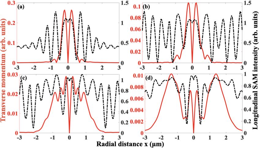
I.    INTRODUCTION

     Light carries both orbital and spin angular momentum. The Poynting vector - consid-
ered to be the vector representative of the flow of energy - has contribution from both the
canonical and spin part of the momentum. The spin contribution in the Poynting vector
(P, or total momentum), introduced by Belinfante through the equation P = Po + Ps
[1, 2] - where Ps represents the spin momentum - is rather enigmatic, since the term Ps
- while being responsible for spin angular momentum - does not contribute to the energy
flow and is therefore considered to be a virtual quantity. On the other hand, Po represents
canonical momentum which is responsible for generating orbital angular momentum (OAM)
l (l = r × Po , where r is the distance from the beam axis), that is directly manifested in
experiments by the rotation of mesoscopic particles about the beam axis in optical tweezers
[3, 4]. The question thus arises whether the manifestation of the elusive Belinfante spin
momentum can be experimentally extracted by similar means.
     It has recently been observed that a longitudinal component of the field - phase-shifted
with respect to the transverse component - plays a major role in the appearance of spin
(polarization) dependent transverse momentum and spin (polarization) independent trans-
verse spin angular momentum (TSAM) [2, 5–9]. This particular feature is well known as
spin momentum locking in condensed matter physics in the context of topological insulators
[10], where special states exist at the outermost surface of the insulator which fall within the
bulk energy gap and permit surface metallic conduction. The carriers in these surface states
are observed with their spin locked at a right-angle to their momentum (spin-momentum
locking) [11]. In optics, this feature is manifested as the transverse component of the Poynt-
ing vector - which represents the flow of momentum - being dependent on helicity (spin) of
the beam. In case of evanescent fields, such non-trivial structures of spin and momentum
density have already been reported [2, 12]. In fact, such a transversely spinning electric field
arising in the case of transverse SAM of light, and resembling the spinning movement of
the spokes of a rolling bicycle wheel, has recently been experimentally achieved [13]. It has
also been shown that the general solution of Mie scattering from a spherical particle, which
has a phase-shifted longitudinal component indeed has the helicity dependent transverse
component of Poynting vector (generally addressed as ‘transverse (spin) momentum’) and
helicity independent transverse spin angular momentum density [8, 14, 15]. Thus, keeping

                                              2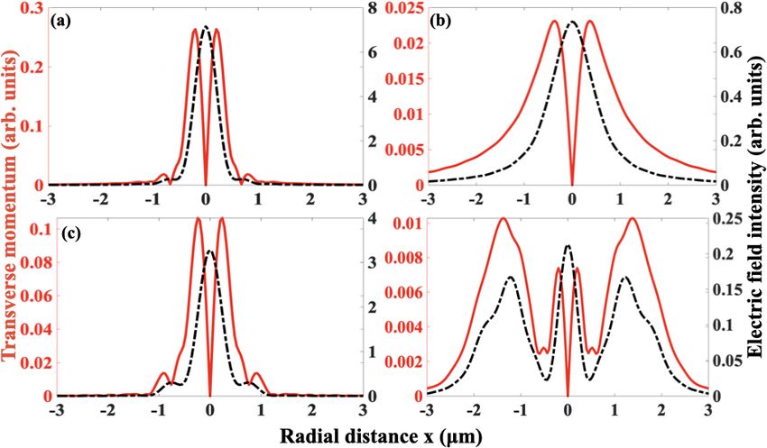
in mind that a tightly focused Gaussian beam has a longitudinal field component which is
phase shifted from the transverse components, the question that naturally arises is whether
such a beam also contains these interesting and exotic properties. Now, it is interesting to
note that while a few practical applications such as nano-displacement probes [16], or gen-
eration of optical vortices [17] have been developed, in most cases the effects of spin-orbit
interaction (SOI) have been quite small, with the magnitude of trajectory shifts reported
due to the Spin Hall Effect (SHE) of light usually being in sub-wavelength regime [18–20].
However, in Refs. [16, 21], the SHE due to scattering of nano-particles was enlarged by
using a imaging system with small focal length or high numerical aperture (N.A.) micro-
scope objectives so that the extent of the SHE covered the microscope exit pupil. Recently,
we showed that optical tweezers - due to the tight focusing involved - causes SOI inher-
ently [22], and the use of a stratified medium in the beam path in the tweezers enhances
polarization-dependent intensity distributions and SHE effects which can lead to controlled
particle manipulation [22, 23]. Thus, it makes sense to explore the use of optical tweezers
in observing spin-momentum locking in Gaussian beams, and investigate the manifestations
of Belinfante spin.
      In this paper, we demonstrate that a tightly focused spin-polarized Gaussian beam indeed
possesses the very same properties of spin-momentum locking that have been observed for
evanescent fields and Mie scattering. We simulate the electric and magnetic field distribution
for an optical tweezers configuration, and the results of our simulations clearly demonstrate
the existence of spin momentum locking in such beams. Our simulations also reveal that the
presence of a stratified medium in the path of the trapping beam can significantly enhance
the magnitude of transverse spin angular momentum and transverse Poynting vector, which
point to the possibility of observing effects of Belinfante spin experimentally. We verify
this experimentally by observing spin-dependent rotational motion of a birefringent particle
around the beam axis for input circularly polarized light propagating through a stratified
medium.

II.     THEORY

      In case of tight focusing of light, the paraxial approximation fails with the generation of a
large longitudinal component of the electric field which is phase shifted from the transverse

                                                 3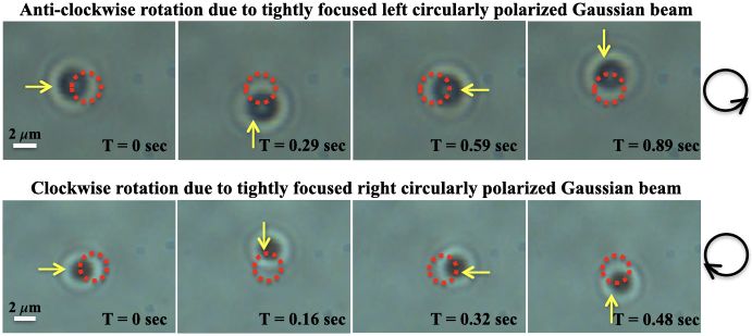
components. Therefore, we calculate the electric field distribution of the tightly focused
beam passing through different refractive index layers (considering both forward and back-
ward propagation) employing the angular spectrum method [24] using Debye-Wolf diffraction
integrals [25]. The expression of the tightly focused beam can be written in the form of a
matrix equation as:
E I + I2 cos2ψ I2 sin2ψ 2iI1 cosψ
x 0
~
Ey = C I2 sin2ψ I0 − I2 cos2ψ 2iI1 sinψ X (1)
Ez −2iI1 cosψ −2iI1 sinψ I0 + I2
~ is the Jones vector of the input field, I0 , I1 and I2 are the Debye integrals (see
where X
Supplementary Information), and C is a constant. The beam propagation direction is in the
z, whereas x, and y denote the transverse plane. The diffraction integrals account for the
forward and backward propagating beams, and contain the Fresnel coefficients (Ts , Tp , Rs
and Rp ) which are required to consider the effect of the stratified medium. We keep track
of the evolution of the electric field in each refractive index layer of the stratified medium
using:
j+1
Ei+
Ti (j, j + 1) = j (2)
Ei+
j+1
Ei−
Ri (j, j + 1) = j . (3)
Ei−
Here, i denotes the polarization states (i.e. s-polarized or p-polarized denoted by s and p
respectively), and the positive and negative signs denote the forward and backward prop-
agating waves, respectively, and j denotes a particular refractive index layer. The output
electric fields can be obtained using the Jones vector for left and right circularly polarized
input light as X ~ = [1 ± i 0]T . Note that the tightly focused electric and magnetic field
enjoy the following symmetry relations (in Gaussian units) [25]:
π
Hx = −Ey ψ − 2
π
Hy = E x ψ − 2
(4)
π
Hz = E z ψ − 2
As circular polarized light propagates along the z direction, the longitudinal spin angular
momentum (LSAM) is generated due to the intrinsic spin (helicity σ) of the light and may
be represented as S ∝ σz, which can be transferred to absorbing birefringent particles to
4cause rotation about their centre of mass. As noted previously, the Poynting vector or
momentum density of the wave can be broken up into the canonical (or orbital, Po ) and
spin (Ps ) components. The latter can also be transferred locally to probe particles resulting
in a torque T ∝ Ps about the beam axis, in contrast to the SAM(S) which generates
rotation around the particle center of mass. Now, the spin angular momentum density (S)
and Poynting vector (P) in an isotropic medium, considering real and µ, in S.I. units are
given as (ignoring dispersion effects):
E × E∗ + µH × H∗
S= (5)
ω [|E|2 + µ|H|2 ]
1
P = Re (E × H∗ ) (6)
2
Using the above relations, we calculate the transverse spin angular momentum (TSAM)
density and transverse momentum (TM, or transverse Poynting vector) density for right
and left circular polarized light. The expressions for right circular polarized light are:
Sx = −4iI1 (I0 + I2 ) sin(ψ)
Sy = 4iI1 (I0 + I2 ) cos(ψ)
Sz = −2i (I02 − I22 )
(7)
Px = 4I1 (I0 + I2 ) sin(ψ)
Py = −4I1 (I0 + I2 ) sin(ψ)
Pz = 2 (I02 − I22 ),
while, those for left circular polarized light are:
Sx = −4iI1 (I0 + I2 ) sin(ψ)
Sy = 4iI1 (I0 + I2 ) cos(ψ)
Sz = 2i I02 − I22
(8)
Px = −4I1 (I0 + I2 ) sin(ψ)
Py = 4I1 (I0 + I2 ) sin(ψ)
Pz = 2 I02 − I22
Clearly we can see that under the change of helicity from +1 to -1, the TSAM remains same,
but the TM flips direction, which confirms that the helicity-independence of the former and
helicity-dependence of the latter are inherent properties of a tightly focused Gaussian beam.
5As discussed earlier, Ts , Tp , Rs and Rp have a crucial role to play in determining the
diffraction integrals which in turn determine the final electric field and magnetic field distri-
butions. Thus, a suitable choice of refractive indices in the stratified medium may provide
us control over the Fresnel’s coefficients which would determine the final distribution of the
electric and magnetic field, and produce interesting effects.
III. NUMERICAL SIMULATIONS
We now run simulations on our experimental system (stratified medium in the path
of the optical tweezers light beam) with the theoretical model developed in the previous
section and observe the occurrences of diverse phenomena dealing with spin momentum
locking, transverse spin and spin momentum effects for input circular polarized Gaussian
beam (T EM00 mode) into the optical tweezers. The laser beam of wavelength 1064 nm is
incident on the 100X objective of numerical aperture 1.4, followed by: a) an oil layer of
refractive index (RI) 1.516, b) a 160 microns thick cover-slip having refractive indices 1.516
and 1.814 (note that the case where the RI = 1.516 is henceforth referred to as the ‘matched
condition’ since this the most general condition employed in optical tweezers experiments
so as to minimize spherical aberration effects in the focused beam spot), c) an aqueous
solution chamber having refractive index of 1.33 with a depth of 35 microns, and finally d) a
glass slide of refractive index 1.516 whose thickness we consider to be semi-infinite (around
2000-3000 microns, being very large considered to other dimensions) as shown in Figure. 1.
We first define a specific coordinate system for our simulation in which the z = 0 is taken
Figure 1: Schematic of our sample chamber setup. (Dimensions not to scale) The z - axis is the
propagation direction, whereas x - axis and y - axis describes the transverse plane.
at 5 µm inside the sample chamber near the cover-slip. Considering this as the origin and
with the dimensions mentioned above, the boundary for oil and objective is at −170 µm, oil
6and cover-slip at −165 µm, cover-slip and sample chamber at −5 µm and sample chamber
and glass slide at +30 µm.
We use both left circular and right circular light as input and compare the results with
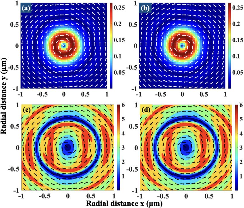
respect to spin-momentum locking. Figure 2a) and 2c) display the TSAM and TM for a left
circularly polarized beam, while Figure 2b) and 2d) displays the same for right circularly
polarized beam at the beam focus. It is clear from the quiver plots that the TM vector flips
sign whereas the TSAM is independent of helicity of the input beam. This establishes our
claim of the existence of spin momentum locking in tightly focused Gaussian beams. With
Figure 2: Transverse component of Poynting vector for a) left circularly polarized beam; b) right
circularly polarized beam; Transverse component of spin angular momentum for c) left circularly
polarized beam; d) right circular polarized beam. All plots are at the focus of the beam for a cover
slip RI of 1.516.
the change in the RI contrast within different layers, the Fresnel coefficients (which determine
the nature of the Debye integrals) change, which would affect the intensity distribution, as
well as the SAM density and Poynting vector. However, in order to probe effects of the
angular momenta on probe particles, we need to trap them first - which makes the field
intensity distribution at the sample region of optical tweezers crucial.
We now shift our attention to this problem, and quantify the intensity profile in the
radial direction inside the sample (water in our case) for cover-slips of different RI and
7also investigate whether the off-axis intensity is sufficient enough for trapping and rotating
micron sized particles given the magnitude of the TM at the same location. We do not
consider scattering effects from a trapped particle, since the scattering (which itself is very
small compared to the transmitted field due to the size of the particle) is predominantly in
the forward direction, and does not contribute to the transverse field anyway.
Figure 3: Radial intensity(black) and transverse spin momentum(red) plot for cover-slips of RI
1.516 at a) focus; b) 2 µm away from focus; and RI 1.814 at (c) focus; (d) 2 µm away from focus
We plot Fig. 3a) and 3b) for the matched condition (cover-slips of RI 1.516) at focus and
2µm axially (Rayleigh range using Gaussian approximation is ∼ 175 µm) away from the
focus, respectively. The intensity distribution is clearly Gaussian with negligible side lobes.
However, since we are working with a fast diverging Gaussian beam, the beam intensity
reduces rapidly. The side lobes also disappear as the beam expands in the radial direction
when we move 2µm beyond the focus as shown in Fig. 3b). It is also interesting to note that
the TM - given by the red line - is zero at the beam center, and increases slightly off-axis,
where the field intensity has fallen substantially. Thus, the possibility of observation of any
effect of the TM on trapped particles is rather low, which is perhaps the main reason why
this has not been observed in conventional optical tweezers.
However, when we increase the RI of the cover-slips to 1.814 (mismatched condi-
tion), the intensity distribution is inhomogeneous, and side lobes are formed as shown in
Fig. 3c) and 3d). Indeed, the intensity at the beam center is substantially lowered for the
8higher RI due to diffraction effects (spherical aberration). The interesting point is that
the TM - depicted by red lines - increases in magnitude off-axis for the increased RI. The
intensity is also high here (close to that at the centre), and we now obtain regions where
both the intensity and transverse spin momentum are high enough in magnitude, so that
particles may be trapped, and also rotate due to the presence of sufficient TM. Thus, a
particle, trapped in this configuration with a stratified medium in the path of the optical
tweezers light beam may be used as a probe to observe the TM.
Figure 4: Longitudinal Spin Angular Momentum Intensity (black) and transverse spin momentum
(red) plot for cover-slip of RI 1.516 at (a) focus; and RI 1.814 at (b) focus; (c) 1 µm; and (d) 2 µm
away from focus
Now, we go on to investigate the LSAM for our system, which we plot in Fig. 4 for
both matched (Fig. 4(a)) and mismatched conditions (Fig. 4(b) - (d)). We observe that the
LSAM - depicted by black lines - is always high at the beam center, where the intensity is also
maximum, which explains the routine observation of the rotation of transparent birefringent
particles around their centre of mass for input circular polarization in optical tweezers [3].
However, at the center, the TM - depicted by red lines - is low. For different axial planes, the
matched condition yields results (displayed in detail in the SI) uninteresting for experiments
since the field intensity falls of rapidly in the radial direction. The mismatched case, though,
needs to be considered in detail. Here, we observe that while the TM has very small radial
lobes at the focus, these start becoming more significant as we move away from the focus
axially. At z=1 µm, we observe the LSAM has several off-axis peaks, whereas the TM still
9falls off quickly from the center. However, at z=2 µm, there is a region where both TM and
LSAM are high off-axis in a particular region - which along with Fig. 3(d) (which shows that
the field intensity is also high in that region) - suggests that it may be possible to observe
interesting effects in particle rotation for this situation. This is what we experimentally
pursue, as we describe in the next section.
IV. EXPERIMENT
We now attempt to observe these effects experimentally on microscopic birefringent
probe particles to verify our simulations. We use a conventional optical tweezers setup
comprising of an inverted microscope (Olympus BX71) with an oil-immersion 100X
objective (Olympus, NA 1.3), and a high power diode laser (1064 nm, 500 mW) coupled
into the back port of the microscope. We control the polarization of light using a quarter
wave plate (QWP), and change the helicity of the beam by rotating the QWP by 90o .
For the probe particles, we use RM257 vaterite liquid crystal particle, which are optically
anisotropic and birefringent so as to transfer angular momentum from the beam into the
particles, and thus probe the effects of TM and LSAM. We construct the sample chamber
using a glass slide and a cover-slip of RI 1.814, into which we add around 20µl of the
aqueous dispersion of RM257 particles [26], which are elliptical, and of mean size 2 × 1 µm.
We ensure that the incident power is constant for both left and right circular polarizations
to avoid any difference in trapping conditions.
On coupling the laser into the microscope, we observe the formation of concentric
off-axis intensity rings (see Supplementary Information, Fig. S1) around the beam center
similar to that displayed in Fig. 3. The image of the rings is optimized by changing the z
− focus of the microscope (imaging performed with transmitted light from the microscope
lamp coupled into a camera attached to the side port of the microscope). As a result,
particles tend to assemble in the ring as we reported in Ref. [22]. However, when we trap
a single particle at the appropriate z-depth, and adjust the microscope focus to image it
adequately, we are able to observe rotation of the particle around the beam axis (see Videos
1 and 2 in the Supplementary Information) - either clockwise or anticlockwise as displayed
in time-lapsed images in Fig. 5. The trajectories of the particle are shown as red dotted
10circles. The first row shows rotation in an anti-clockwise direction. When we modify the
orientation of the QWP by 90o , the rotation direction of particle flips (becomes clockwise),
as shown in the second row of time lapsed images in Fig. 5. However, these are for two
Figure 5: Time-lapsed frames of a video recording showing the rotation of particles by tightly
focused circulation polarized light. The red circle marks the trajectory of the particle and yellow
arrow indicates the position in that time frame. The rightmost circular panel show the orientation
of particle’s movement.
different particles in separate experiments. We have changed the orientation of the QWP
for the same particle as well, but often lose the particle from the trap in that process.
This is because - the input helicity - or the Jones vector in Eq. 1 is modified, so that the
output electric field intensity in the sample plane is also modified - as a result of which the
trap often becomes unstable. However, in a few experiments, we do manage to keep the
particle trapped by rotating the QWP very slowly. One such case we report here - which is
shown in Video 3, and in time-lapsed images in Fig. 6(i). In this case, we observe rotation
of the particle both around the axis of the beam in the clockwise direction (input RCP)
demonstrated in Figs. 6(a)-(c), and around the particle body axis in the anti-clockwise
direction for input LCP as demonstrated in Figs. 6(d)-(f). Note that, while the former
is due to the enhanced TM in our system, the latter is invariably the demonstration of
the LSAM, which increases over TM when the axial trapping depth is modified. We have
verified on this in our description of Fig. 4, where - as we change the z-distance from the
focus, the TM and LSAM behave differently. We believe that even when we change the
QWP slowly, the intensity at the trapping plane still changes enough to change in the
11equilibrium position of the trapped particle in the z direction. This is what results in the
trapped particle sampling higher LSAM than TM (note that the LSM at z = 1 µm is
more than the TM, whereas at z = 2 µm, these are similar). This is also apparent in
Video 3 (snapshots in Fig. 6 - compare the upper and lower rows), where the particle seems
to undergo a change in shape as we change the QWP - which clearly indicates that the
z-depth is changed. The fact that the effects of TM and LSAM are different as the trapping
depth is modified is thus apparent in our experiment. We also observe that the frequency
of rotation increases as we increase power as is shown in Fig. 6(ii), which is expected as
the magnitudes of both electric and magnetic field will increase as we increase the input
intensity. We demonstrate these events in Videos 4-7 in the SI.
(a) T = 0 sec (b) T = 0.18 sec (c) T = 0.36 sec
(d) T = 0 sec (e) T = 0.15 sec (f) T = 0.25 sec
(ii)
(i)
Figure 6: Time-lapsed frames of a video recording showing the rotation of particles when the input
light helicity is changed during the experiment. Figs. (a) to (c) denote rotation around the beam
axis with input RCP, while (d) to (e) denote rotation around the center of mass with input LCP.
The red circle marks the trajectory of the particle in (a)-(c). The rightmost circular panel show
the orientation of particle’s movement for (a)-(c) and (d)-(f). (ii) Rotational frequency (around the
beam axis) of a particle as a function of input laser power.
The crucial issue is to decide whether the canonical (orbital) momentum Po is responsible
for the rotation of particles around the beam axis. This, however, cannot be the case
since there is no dependence on input helicity in Po , so the direction of rotation should
be independent of the helicity of input light. Thus, we can conclude that the rotation we
observe is solely due to the effect of the Belinfante spin, which makes our experiment perhaps
the first observation of this erstwhile elusive quantity for propagating light fields. We would
also like to point out here that it is not feasible that this rotation occurs due to azimuthally
12asymmetric scattering from the particle, which may lead to the generation of orbital angular
momentum [27], since the particle comes to rest as soon we remove the QWP.
V. CONCLUSIONS
We observe that the TM or the transverse Poynting vector of a tightly focused Gaussian
beam (optical tweezers) is explicitly helicity-dependent, while the TSAM remains helicity
independent. This dependence demonstrates spin-momentum locking for tightly focused
Gaussian beams. In addition, the TM is zero at the beam center and increases off-axis as we
introduce a stratified medium in the path of the beam and increase its RI contrast. Thus,
when we use a cover slip with RI 1.814 (mismatched condition) for the sample chamber of
the optical tweezers, we observe in our simulations that the transverse extent of both the
TM and field intensity increase with axial distance from the beam focus. As a result, there
is sufficient overlap of high intensity - which can facilitate optical confinement; and high
TM - which can lead to the observation of rotational effects around the beam axis. We
validate this observation experimentally with birefringent particles where we demonstrate
both clockwise and anti-clockwise rotation around the beam axis for input RCP and LCP
with cover-slips of RI 1.814. Interestingly, when we change the helicity in the course of an
experiment, we sometimes observe a transition from rotation around the beam axis (in a
particular sense) to rotation about the particle axis (in the opposite sense). This implies
that the particle samples predominantly TM in one case and LSAM in the other case.
This observation is also expected from our simulations which demonstrate that the relative
magnitudes of TM and LSAM are modified at different axial distances from the trapping
beam focus, so that as the axial position of the particle is slightly modified in the process of
changing helicity using a QWP, either the TM or the LSAM dominate. The rotation around
the beam axis is the clear manifestation of Belinfante spin, which is solely responsible for the
spin-dependence of the Poynting vector, the canonical component being spin-independent.
We believe this to be a simple but robust way to observe the effects of Belinfante spin,
which have often proved to be rather elusive to experimental observation. We are presently
in the process of extending our studies to the tight focusing of higher-order Gaussian beams
(Hermite-Gaussian) including those carrying intrinsic orbital angular momentum (Laguerre-
Gaussian) to determine more interesting and intriguing effects of the interaction between
13spin and orbital angular momentum in the presence of a stratified medium.
VI. ACKNOWLEDGMENTS
The authors acknowledge the SERB, Department of Science and Technology, Govt of
India (project no. EM R/2017/001456) and IISER Kolkata, Mohanpur, India, for research
funds. They also acknowledge Mr. Sourav Islam of IISER Kolkata for help in the experimen-
tal measurements, and Dr. Georgios Vasilakis of Foundation for Research and Technology-
Hellas, Greece for critical comments.
[1] F. J. Belinfante, Physica 7, 449 (1940).
[2] K. Y. Bliokh, A. Y. Bekshaev, and F. Nori, Nature Communications 5, 3300 (2014).
[3] M. Friese, T. Nieminen, N. Heckenberg, and H. Rubinsztein-Dunlop, Nature 394, 348 (1998).
[4] T. A. Nieminen, A. B. Stilgoe, N. R. Heckenberg, and H. Rubinsztein-Dunlop, Journal of
Optics A: Pure and Applied Optics 10, 115005 (2008), URL https://doi.org/10.1088%
2F1464-4258%2F10%2F11%2F115005.
[5] A. Aiello, P. Banzer, M. Neugebauer, and G. Leuchs, Nature Photonics 9, 789 (2015).
[6] K. Y. Bliokh, D. Smirnova, and F. Nori, Science 348, 1448 (2015).
[7] A. Y. Bekshaev, K. Y. Bliokh, and F. Nori, Physical Review X 5, 011039 (2015).
[8] S. D. Gupta, N. Ghosh, and A. Banerjee, Wave optics: Basic concepts and contemporary trends
(CRC Press, 2015).
[9] J. S. Eismann, P. Banzer, and M. Neugebauer, Physical Review Research 1, 033143 (2019).
[10] M. Z. Hasan and C. L. Kane, Reviews of modern physics 82, 3045 (2010).
[11] D. Hsieh, D. Qian, L. Wray, Y. Xia, Y. S. Hor, R. J. Cava, and M. Z. Hasan, Nature 452, 970
(2008).
[12] T. Van Mechelen and Z. Jacob, Optica 3, 118 (2016).
[13] T. Bauer, M. Neugebauer, G. Leuchs, and P. Banzer, Physical Review Letters 117, 013601
(2016).
[14] S. Saha, A. K. Singh, S. K. Ray, A. Banerjee, S. D. Gupta, and N. Ghosh, Optics letters 41,
4499 (2016).
14[15] S. Saha, A. K. Singh, N. Ghosh, and S. D. Gupta, Journal of Optics 20, 025402 (2018).
[16] O. G. Rodríguez-Herrera, D. Lara, K. Y. Bliokh, E. A. Ostrovskaya, and C. Dainty, Physical
Review Letters 104, 253601 (2010).
[17] E. Brasselet, N. Murazawa, H. Misawa, and S. Juodkazis, Physical Review Letters 103, 103903
(2009).
[18] K. Y. Bliokh, F. J. Rodríguez-Fortuño, F. Nori, and A. V. Zayats, Nature Photonics 9, 796
(2015).
[19] K. Bliokh and A. Desyatnikov, Phys. Rev. A 79 (2009).
[20] H. Rubinsztein-Dunlop, A. Forbes, M. V. Berry, M. R. Dennis, D. L. Andrews, M. Mansuripur,
C. Denz, C. Alpmann, P. Banzer, T. Bauer, et al., Journal of Optics 19, 013001 (2016).
[21] K. Y. Bliokh, E. A. Ostrovskaya, M. A. Alonso, O. G. Rodríguez-Herrera, D. Lara, and
C. Dainty, Optics Express 19, 26132 (2011).
[22] B. Roy, N. Ghosh, S. D. Gupta, P. K. Panigrahi, S. Roy, and A. Banerjee, Physical Review A
87, 043823 (2013).
[23] B. Roy, N. Ghosh, A. Banerjee, S. D. Gupta, and S. Roy, New Journal of Physics 16, 083037
(2014).
[24] A. Rohrbach, Physical Review Letters 95, 168102 (2005).
[25] B. Richards and E. Wolf, Proceedings of the Royal Society of London. Series A. Mathematical
and Physical Sciences 253, 358 (1959).
[26] K. Sandomirski, S. Martin, G. Maret, H. Stark, and T. Gisler, Journal of Physics: Condensed
Matter 16, S4137 (2004).
[27] A. Mondal, B. Roy, and A. Banerjee, Optics Express 23, 8021 (2015).
15You can also read