High order plasmonic vortex generation based on spiral nanoslits
←
→
Page content transcription
If your browser does not render page correctly, please read the page content below
PAPER • OPEN ACCESS

High order plasmonic vortex generation based on spiral nanoslits
To cite this article: Jing Fang et al 2021 New J. Phys. 23 033013

View the article online for updates and enhancements.

                               This content was downloaded from IP address 46.4.80.155 on 02/06/2021 at 04:13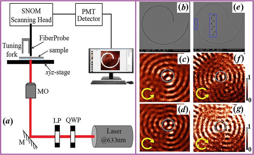
New J. Phys. 23 (2021) 033013                                                                https://doi.org/10.1088/1367-2630/abe72c

                                 PAPER

                                 High order plasmonic vortex generation based on spiral
O P E N AC C E S S
                                 nanoslits
R E C E IVE D
1 December 2020
                                 Jing Fang1 , Changda Zhou1 , Zhen Mou1 , Shuyun Wang1 , Jiayi Yu1 , Yuanjie Yang2 ,
R E VISE D
6 February 2021                  Gregory J Gbur3 , Shuyun Teng1 , ∗ and Yangjian Cai1 , ∗
                                 1
AC C E PTE D FOR PUBL IC ATION
                                     Shandong Provincial Key Laboratory of Optics and Photonic Device & School of Physics and Electronics, Shandong Normal
17 February 2021                     University, Jinan 250014, People’s Republic of China
                                 2
                                     School of Astronautics and Aeronautics, University of Electronic Science and Technology of China, Chengdu 611731, People’s
PUBL ISHE D
10 March 2021                        Republic of China
                                 3
                                     Department of Physics and Optical Science, University of North Carolina at Charlotte, Charlotte, North Carolina 28223, United
                                     States of America
Original content from            ∗
                                     Authors to whom any correspondence should be addressed.
this work may be used
under the terms of the           E-mail: tengshuyun@sdnu.edu.cn and yangjiancai@sdnu.edu.cn
Creative Commons
Attribution 4.0 licence.         Keywords: plasmonic vortex, nanostructure, topological charge, near-field diffraction
Any further distribution
of this work must
maintain attribution to
the author(s) and the            Abstract
title of the work, journal
citation and DOI.                Highly localized plasmonic vortices carrying orbital angular momentum are of importance for
                                 many applications. Yet, it is a challenge to generating plasmonic vortex with a high topological
                                 charge because of no available technique. Here, a novel plasmonic vortex generator is proposed
                                 based on spiral nanoslits etched in a metal film, which can produce a high order plasmonic vortex.
                                 The consecutive spiral nanoslit can generate plasmonic vortex with high intensity and the
                                 segmented nanoslits enhances the controllability of the plasmonic vortex, which are demonstrated
                                 numerically and experimentally. High order plasmonic vortex generation will broaden the
                                 prospects for plasmonic vortices in practical applications for nanomanipulation and
                                 nanofabrication.

                                 1. Introduction

                                 Optical vortex is used to describe a light field possessing a helical wave front and a doughnut-shaped
                                 intensity distribution in its cross-section. Since vortex beam possesses orbital angular momentum (OAM)
                                 and vortex beams with different topological charges may be multiplexed and demultiplexed, studies of
                                 vortex beams have attracted much attention in the fields of optical communication [1, 2], particle trapping
                                 [3, 4], nanofabrication [5] and quantum information processing [6, 7]. Generally, the phase of an optical
                                 vortex can be expressed by a term of exp(jmϕ), where ϕ is the azimuthal angle and m denotes the
                                 topological charge corresponding to the order of the optical vortex [8]. Optical vortices with different
                                 orders have been produced by using various methods including cylindrical lenses [9], spiral phase plate
                                 [10], spatial light modulator [11] and optical wave-guide [12].
                                     Recently, plasmonic vortices (PVs) have aroused a lot of interest due to their high localization. Different
                                 from the far-field optical vortices, PVs result from the superposition of surface plasmon polaritons (SPPs)
                                 or the surface waves excited by nanostructures. Most of the above-mentioned methods are unavailable for
                                 generating the PVs. Thus, various nanostructures have been proposed to generate PVs and they are spiral
                                 nanoslits [13–16], single and double ring distributed nanoslits [17–19] and metasurface geometries
                                 [20–22]. Among these methods, a spiral slit has the advantage of being a simple structure that is convenient
                                 to manufacture and the generated PVs have high intensity. Nevertheless, high order PVs generated by a
                                 common spiral such as Archimedes spiral or Fermat’s spiral have poor quality because of the damp effect of
                                 SPPs. Even for the Archimedes spirals with multiple arms [13, 23], the generated PVs are not ideal because
                                 of the interference effect of the deuterogenic field [24]. In our former work, we propose α spiral and the
                                 topological charge of the PV modified passively by α spiral still takes the limited value [25, 26]. This is the
                                 reason that spiral slits are rarely used in the generation of the higher order PVs.

                                 © 2021 The Author(s). Published by IOP Publishing Ltd on behalf of the Institute of Physics and Deutsche Physikalische Gesellschaft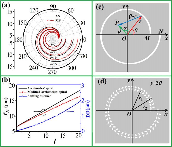
New J. Phys. 23 (2021) 033013                                                                                                J Fang et al

   Figure 1. (a) Trajectories of Archimedes spirals (AS) and the modified spirals (MS) with l taking 2, 5, 10 and 15, (b) the end
   positions of two spirals (rN ) and their distance difference (DD), and (c) the proposed consecutive and (d) segmented spiral
   nanostructures.

    The aim of this work is to explore simple spiral nanostructures to generate high order PVs carrying large
OAM. The SPP fields excited by the proposed spirals actively compensate the damp effect of SPPs during
the propagation. The spiral nanostructure may be consecutive or segmented nanoslits. The consecutive
spiral nanoslit can generate high order PV with high intensity and the segmented nanoslit structure further
increases the topological charge of the generated PV without increasing the size of nanostructure. The
design principle provides the spiral trajectory of the proposed spiral nanostructures. The effective
compensation of the damped SPPs by using the compressed spirals makes the generated high order PVs
have high quality. The numerical simulations and experimental measurement verify the performance of the
proposed spiral structures. This works paves a road for the generation of higher order PVs by a simple spiral
and it will bring more possibility for expanding the applications of PVs in optical micro-manipulation,
integrated optical coding and nanofabrication.

2. Design principle

An ideal optical vortex with the topological charge of m has annular intensity distribution and its phase
uniformly changes m times of 2π around the phase singularity. In order to generate one ideal PV carrying
larger OAM, the amplitude and phase of SPPs contributing to the formation of PV are the key factors. As
we know, the phase of SPPs may be introduced through the propagation distance or by using the rotation of
nanounits, and the amplitude damp of SPPs during the longer distance propagation cannot be neglected.
Combining the exponential damp rule of SPPs along the interface of the metal and vacuum, we propose a
modified spiral structure on basis of the common Archimedes spiral, and the trajectory of this spiral can be
expressed by
                                              lλspp θ            lλspp
                                    r = r0 +           2 − exp            ,                               (1)
                                                2π                2πa
where r0 is the initial radius and the integer l denotes the geometrical charge of the spiral slit, λspp is the SPP
wavelength. The parameter a depends on the metal material. Here, the radius r of spiral linearly increases
with the angular coordination of θ. If we temporarily neglect the damp effect of SPPs, the parameter of a
takes the infinite and the above expression can be simplified into the denotation of an Archimedes spiral,
namely, r = r0 + lθλspp /2π. The difference between the modified spiral and Archimedes spiral can be seen
from the curves shown in figures 1(a) and (b), where the value of l takes 2, 5, 10 and 15. The black solid and
red dash lines denote the Archimedes spirals and the modified spirals, respectively.
    It can be seen that the trajectories of the modified spiral and Archimedes spiral overlap as the
geometrical charge of l takes 2. Their difference gets obvious with increase of l. The modified spiral seems to
be radially compressed with respect to the Archimedes spiral, and the gap of the modified spiral between
the start and the end is smaller than that of the Archimedes spiral with the same geometric charge. The
variation of the spiral end with the value of l can be clearly seen from the curves given in figure 1(b), where

                                                       2
New J. Phys. 23 (2021) 033013 J Fang et al
the distance difference of the end positions for Archimedes spiral and the modified spiral are also given.
Obviously, the modification of the spiral with larger geometric charge is much larger.
The SPPs excited by the spiral consecutive nanoslit with the circularly polarized light illumination
propagate towards the center of spiral nanoslit, like the case shown in figure 1(c), and their superposition at
the position near the center can be calculated approximately through the integration operation
E(ρ, α, z) = A0 e−κz−R/δspp e j[±θ+kspp r−kspp ρ cos(α−θ)] dθ. (2)
Here, r and θ denote the radial and azimuthal coordinates of a small section of nanoslit, ρ, α and z are
the radial, azimuthal and vertical coordinates of the observation point P near the center. A0 equals to
E0 /(jRλspp ) with E0 denoting the amplitude of the incident field and R = |ρ − r| = [ρ2 + r2 − 2ρr cos(α −
θ)]1/2 representing the distance from the slit to the observation point. kspp is the wave number of SPPs, κ is
the damped factor, and they satisfy kspp =(k0 2 –κ2 )1/2 with k0 the wave number in vacuum. δ spp is the
attenuation distance of the SPPs along the smoothing metal surface, which satisfies the relation of δ spp =
εr 2 [(εr + 1)/εr ]/(k0 εi ), where εr and εi denote the real and imaginary part of the dielectric function of
silver.
The plus sign in the second exponential term of equation (2) is for the left-handed circular polarization
(LCP) and the minus sign is for the right-handed circular polarization (RCP). Suppose the amplitudes of all
SPP fields are the same, the above integration can be deduced into the following form
E(ρ, α, z) ∝ e j(l±1)α Jl±1 (kspp ρ), (3)
where J i represents the ith order Bessel function. The spiral phase indicates that the optical field is a vortex
of l ± 1 order. Theoretically, the PV of any order can be generated by the spiral nanoslit even when l takes
larger values. Actually, the damp of SPPs gets obvious as l is larger and the generated vortex has poor
quality. This is the reason for proposing the modified spiral to generate the high order PV. The modification
of the spiral trajectory effectively offset the damp effect of SPP field.
For the consecutive spiral nanoslit with larger geometrical charge, the size of spiral is larger because of
the larger gap. If a consecutive spiral slit is replaced by multiple nanoslit segments locating on the modified
spiral trajectory, these short nanoslits can rotate around their center to introduce the additional phase
though the intensity of optical field may decrease. When the nanoslit with the coordinates of r and θ rotates
an angle of γ, the SPP field excited by this nanoslit is proportional to exp(jσγ)cos(θ–γ), where σ = ±1
with the positive sign for the LCP and the negative sign for the RCP. When the segmented nanoslits are
arranged on two parallel trajectories with the separation of λSPP /2 and two adjacent nanoslits are
orthogonal, as shown in figure 1(d), the SPP field excited by two nanoslits with the same angular coordinate
of θ is proportion to exp[jσ(2γ –θ)] [26]. Thus, insert this expression into equation (2) and let γ equal to
nθ, the generated SPP field by all the nanoslits can be deduced into
E(ρ, α, z) ∝ e j[l±(2n−1)]α Jl±(2n−1) (kspp ρ). (4)
Obviously, the PV with the topological charge taking l ± (2n − 1) is formed. We rewrite this topological
charge into the l ± 1 ± 2(n − 1). This result indicates that the topological charge of the generated PV
includes three parts. The first part of l comes from the geometrical charge of the spiral trajectory, the
number 1 reflects the contribution of the incident circular polarization carrying the spin angular
momentum and the third part of 2(n − 1) corresponds to the contribution of the rotated nanoslits.
Therefore, the segmented nanoslits can further increase the topological charge of the generated PV through
the rotation of nanoslits without increasing the size of spiral nanostructure.
3. Numerical simulations
In order to verify the availability of our proposed spiral nanostructures for the generation of high order
PVs, we simulate numerically the near-field diffraction of the proposed spiral nanostructures. For
comparison, the diffraction by Archimedes spiral nanoslit is also simulated and figure 2(a) gives the
diffraction intensity and phase distributions of Archimedes spiral nanoslit with l = 5, where the nanoslit is
etched in the silver film with the thickness taking 150 nm. The initial radius of spiral is 6 μm and the slit
width is 200 nm. The illuminating light is the LCP light with the wavelength of 633 nm.
One can see that the simulated results show the intensity distribution is not uniform and the phase
pattern is not symmetric. The central bright ring among the intensity pattern seems to have an opening on
the top and one first-order phase singularity away from the center interferes the phase change along the
azimuthal direction, as shown by the inserted arrows. These cases indicate the formed optical field deviates
3New J. Phys. 23 (2021) 033013 J Fang et al
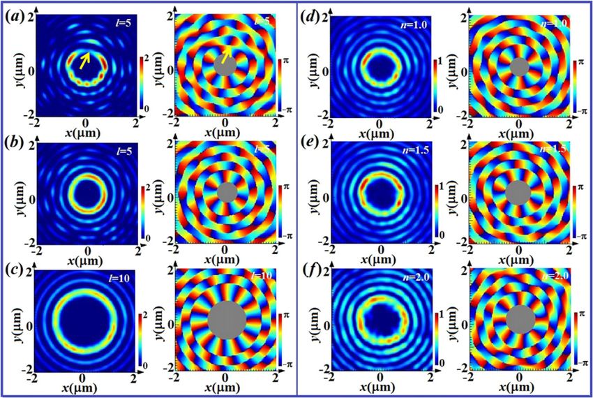
Figure 2. Diffraction intensity and phase distributions of (a) Archimedes spiral slits with l = 5, [(b) and (c)] the proposed spiral
slits with l = 5 and 10, and the segmented nanoslits with the rotation parameters satisfying (d) n = 1.0, (e) 1.5 and (f) 2.0, where
the illumination light takes the LCP.
from the pure integral vortex. More simulations show that the deviation gets severer with increase of the
geometrical charge. This kind of field may cause abnormal behavior in practical applications, such as an
abrupt acceleration of trapped nanometer particles.
Based on our proposed spiral model, we simulate the intensity and phase distributions of the modified
spiral nanoslits and figures 2(b) and (c) give the results with a = 28 μm and l = 5 and 10 under the LCP
light illumination. From figure 2(b), one can see that the intensity distribution is the annular shape and the
phase uniformly changes 6 times of 2π in anticlockwise direction. These results indicate that the generated
optical vortices are the ideal 6-order PVs, which is better than the one generated by Archimedes spiral.
Figure 2(c) show the intensity distribution is the annular shape and the phase uniformly changes 11 times
of 2π. These results verify the active modification of spiral trajectory is valid for the generation of high
order PV. In fact, the ideal PV with the topological charge no less than 20 can be obtained because of the
compensation of the damped SPP field.
Figures 2(d)–(f) give the simulated intensity and phase distributions of segmented nanoslits with the
rotation angle taking γ = θ, 1.5θ and 2θ and the parameters of spiral trajectory taking the same values as
figure 2(b). From the intensity distributions, it is easy to see that the central bright ring gets larger with
increase of the ratio of γ to θ. The phase distributions confirm that topological charge changes from 6, 7 to
8. The topological charge of the generated vortex satisfies the relation of l + 1 + 2(n − 1). With comparison
to figure 2(b), the segmented spiral structure increases the topological charge of the generated PV. This is
consistent with the theoretical prediction. It needs to be pointed out that for ensuring the equivalent
intensity of SPP field excited by the segmented nanoslit with different radial coordinate, the length of the
segmented nanoslit increases from 300 nm to 550 nm with increase of its angular coordinate.
All these results are obtained by using the finite difference time domain method [27–29]. The spiral
nanostructures are etched in the silver film with the thickness taking 150 nm and the SPP wavelength equals
to λspp = 613 nm for the illuminating wavelength of 633 nm. The complex dielectric constant of silver is
taken from the value given by Palik [30]. The perfectly matched layer is chosen as the adsorbing boundary
and the minimum mesh cell takes 2 nm. The calculation region is set 20 μm × 20 μm × 6 μm and the
monitor plane is set at 200 nm above the silver film. The incident polarization takes the LCP. For the RCP,
the generated vortex by any spiral nanostructure is similar to the one with LCP light illumination except
that the topological charge is smaller 2 than the latter.
4New J. Phys. 23 (2021) 033013 J Fang et al
Figure 3. (a) Experiment setup, [(b) and (e)] SEM pictures of the fabricated Archimedes spiral slit of l = 10 with the width and
the initial radius taking 200 nm and 6 μm, and the proposed spiral nanoslits with the length taking the value from 300 nm to
550 nm, and the intensity distributions with [(c) and (d)] the LCP and [(f) and (g)] RCP light illumination. Where the inserted
nanostructure in (e) is the enlarged part of the segmented nanoslits and the inserted arrows in [(c), (d), (f) and (g)] denote the
incident polarization.
4. Experiment measurement
The practical experiment is performed to testify the high order PV generation based on the proposed spiral
nanostructure. The experiment includes the preparation of the samples and the measurement of the
near-field diffraction. The preparation process of the sample contains the film deposition and the nanoslit
fabrication. The metal film deposited onto the glass substrate is achieved with the help of the magnetron
sputtering method. The metasurface sample is fabricated by the focused ion beam etching method. For
comparison, we manufacture two samples. The first sample is an Archimedes spiral slit with the width and
the initial radius taking 200 nm and 6 μm, and the second one is a proposed spiral nanostructure consisting
of segmented nanoslits with the width taking 200 nm and the length taking the unequal values from 300 nm
to 550 nm. The rotation angle of nanoslit and its position angle satisfy the relation of γ = 1.5θ. The
geometric charge of two spirals takes l = 10. Figures 3(b) and (e) give the scanning electron microscopy
(SEM) images of two samples.
Put one fabricated sample into the light path of figure 3(a), we detect its diffraction intensity
distribution by using the scanning near-field optical microscopy. The linearly polarized light with the
wavelength of 633 nm emitted from the laser passes through the combination of a linear polarizer and a
quarter wave plate, and then turns into the LCP or RCP light. A 20 × microscope objective is used to focus
the incident light on the sample. The fiber probe collects the light field behind the nanostructure and
transmit it to the detector. Finally, the near-field diffraction intensity pattern is output on the screen or
recorded in the file. Figures 3(c) and (d) are the measured intensity distributions of the Archimedes spiral
nanoslit with LCP and RCP light illumination, and figures 3(f) and (g) are the measured intensity
distributions of the segmented nanoslits located on the modified spiral trajectory. Where the arrows
inserted in patterns denote the incident polarization, and for convenience, the regions circled by the dashed
lines highlight the difference of the optical fields near the center.
From figures 3(c) and (d), we can see that the intensity distributions near the center consist of three
discrete spots, and these distributions deviate seriously the ideal PVs, like the theoretical prediction.
Differently, the intensity distributions near the center of figures 3(f) and (g) close to the annular shape.
Though the annular shapes are not perfect due to the manufacturing precision, they still indicate the quality
of the generated PVs has been improved by using the segmented nanoslits at the modified spiral trajectory.
Because of the opposite contributions coming from the spin orbit momentum carried by the incident
circular polarization, the sizes of the discrete spots in figure 3(c) and the annular distribution in figure 3(f)
are larger than those in figures 3(d) and (g). That means the topological charge of PV for the LCP light
illumination is larger than the case for the RCP light illumination.
5New J. Phys. 23 (2021) 033013 J Fang et al
5. Conclusions
In summary, we explore theoretically and experimentally the generation of high order PVs based on spiral
nanoslits. The proposed empirical expression for the spiral provides the theoretical basis for actively
generating high order PVs with high quality under circularly polarized light illumination. Two kinds of
spiral nanostructures including the consecutive and segmented nanoslits provide more choices to generate
the PV carrying larger OAM. Numerical simulations and experiment measurement verify the availability of
our proposed spiral nanostructures for the high order PV generation. The study of this article breaks the
limitation of the spiral slit in generating the PV with larger topological charge, and the proposed spiral
nanostructures pave a path to generate the high order PVs by using the simple spiral structure. We believe
this work must be helpful for promoting the applications of PVs carrying larger OAM in more relevant
fields.
Acknowledgments
Authors thanks the support by National Natural Science Foundation of China (10874105, 62002208) and
Shandong Provincial Natural Science Foundation (ZR2020KA009).
Data availability statement
All data that support the findings of this study are included within the article (and any supplementary files).
Disclosures
The authors declare no conflicts of interest.
ORCID iDs
Jing Fang https://orcid.org/0000-0002-3854-5909
Zhen Mou https://orcid.org/0000-0001-9263-5481
Shuyun Wang https://orcid.org/0000-0002-9026-9489
Shuyun Teng https://orcid.org/0000-0001-6071-963X
References
[1] Jia P, Yang Y, Min C J, Fang H and Yuan X-C 2013 Sidelobe-modulated optical vortices for free-space communication Opt. Lett.
38 588–90
[2] Willner A E et al 2015 Optical communications using orbital angular momentum beams Adv. Opt. Photon. 7 66–106
[3] Williams S J, Kumar A, Green N G and Wereley S T 2009 A simple, optically induced electrokinetic method to concentrate and
pattern nanoparticles Nanoscale 1 133–7
[4] Ng J, Lin Z F and Chan C T 2010 Theory of optical trapping by an optical vortex beam Phys. Rev. Lett. 104 103601
[5] Toyoda K, Miyamoto K, Aoki N, Morita R and Omatsu T 2012 Using optical vortex to control the chirality of twisted metal
nanostructures Nano Lett. 12 3645–9
[6] Nicolas A, Veissier L, Giner L, Giacobino E, Maxein D and Laurat J 2014 A quantum memory for orbital angular momentum
photonic qubits Nat. Photon. 8 234–8
[7] Ding D S, Zhang W, Zhou Z Y, Shi S, Xiang G Y, Wang Z S, Jiang Y K, Shi B S and Guyo G C 2014 Quantum storage of orbital
angular momentum entanglement in an atomic ensemble Phys. Rev. Lett. 114 050502
[8] Yao A M and Padgett M J 2011 Orbital angular momentum: origins, behavior and applications Adv. Opt. Photon. 3 161–204
[9] Beijersbergen M W, Allen L, Van der Veen H and Woerdman J P 1993 Astigmatic laser mode converters and transfer of orbital
angular momentum Opt. Commun. 96 123–32
[10] Kotlyar V V, Elfstrom H, Turunen J, Almazov A A, Khonina S N and Soifer V A 2005 Generation of phase singularity through
diffracting a plane or Gaussian beam by a spiral phase plate J. Opt. Soc. Am. A 22 849–61
[11] Ostrovsky A S, Rickenstorff-Parrao C and Arrizón V 2013 Generation of the ‘perfect’ optical vortex using a liquid-crystal spatial
light modulator Opt. Lett. 38 534–6
[12] Cai X, Wang J, Strain M J, Johnson-Morris B, Zhu J, Sorel M, O’Brien J L, Thompson M G and Yu S 2012 Integrated compact
optical vortex beam emitters Science 338 363–6
[13] Kim H, Park J, Cho S-W, Lee S-Y, Kang M and Lee B 2010 Synthesis and dynamic switching of surface plasmon vortices with
plasmonic vortex lens Nano Lett. 10 529–36
[14] Cho S-W, Park J, Lee S-Y, Kim H and Lee B 2012 Coupling of spin and angular momentum of light in plasmonic vortex Opt.
Express 20 10083–94
[15] Spektor G et al 2017 Revealing the subfemtosecond dynamics of orbital angular momentum in nanoplasmonic vortices Science
355 1187–91
6New J. Phys. 23 (2021) 033013 J Fang et al
[16] Wang H, Liu L, Zhou C, Xu J, Zhang M, Teng S and Cai Y 2019 Vortex beam generation with variable topological charge based on
a spiral slit based on a spiral slit Nanophotonics 8 317–24
[17] Lee S-Y, Kim S-J, Kwon H and Lee B 2015 Spin-direction control of high-order plasmonic vortex with double-ring distributed
nanoslits IEEE Photon. Technol. Lett. 27 705–8
[18] Wang H, Liu L, Liu C, Li X, Wang S, Xu Q and Teng S 2018 Plasmonic vortex generator without polarization dependence New J.
Phys. 20 033024
[19] Du L, Xie Z, Si G, Yang A, Li C, Lin J, Li G, Wang H and Yuan X 2019 On-chip photonic spin Hall lens ACS Photon. 6 1840–7
[20] Chen C-F, Ku C-T, Tai Y-H, Wei P-K, Lin H-N and Huang C-B 2015 Creating optical near-field orbital angular momentum in a
gold metasurface Nano Lett. 15 2746–50
[21] Chen S, Cai Y, Li G, Zhang S and Cheah K W 2016 Geometric metasurface fork gratings for vortex-beam generation and
manipulation Laser Photon Rev. 10 322–6
[22] Tan Q, Guo Q, Liu H, Huang X and Zhang S 2017 Controlling the plasmonic orbital angular momentum by combining the
geometric and dynamic phases Nanoscale 9 4944–9
[23] David A, Gjonaj B and Bartal G 2016 Two-dimensional optical nanovortices at visible light Phys. Rev. B 93 121302
[24] Yang Y, Wu L, Liu Y, Xie D, Jin Z, Li J, Hu G and Qiu C-W 2020 Nano Lett. 20 6774–9
[25] Lu X, Han Y, Lv H, Mou Z, Zhou C, Wang S and Teng S 2020 α spiral nanoslit and the higher order plasmonic vortex generation
Nanotechnology 31 305201
[26] Zhou C D, Mou Z, Bao R, Li Z and Teng S Y 2021 Compound plasmonic vortex generation based on spiral nanoslits Front. Phys.
16 33503
[27] Zhang Q, Wang H, Liu L and Teng S 2018 Generation of vector beams using spatial variation nanoslits with linearly polarized
light illumination Opt. Express 26 24145–54
[28] Teng S, Zhang Q, Wang H, Liu L and Lv H 2019 Conversion between polarization states based on a metasurface Photon. Res. 7
246–50
[29] Bao R, Mou Z, Zhou C, Bai Q, He X, Han Z, Wang S and Teng S 2020 Generation of diffraction-free beams using resonant
metasurfaces New J. Phys. 22 103064
[30] Palik E D 1998 Handbook of Optical Constants of Solids (New York: Academic)
7You can also read