Study of dynamic pressure on the packer for deep-water perforation
←
→
Page content transcription
If your browser does not render page correctly, please read the page content below
Open Physics 2021; 19: 215–223
Research Article
Hao Huang, Qiao Deng*, and Hui Zhang
Study of dynamic pressure on the packer for
deep-water perforation
https://doi.org/10.1515/phys-2021-0025
received September 09, 2019; accepted March 11, 2021
1 Introduction
Abstract: The packer is one of the most important tools in With the rapid development of oil and gas industry in
deep-water perforation combined well testing, and its recent years, the exploration of offshore oil and gas
safety directly determines the success of perforation test resources has gradually become the focus, especially in
operations. The study of dynamic perforating pressure on deep water [1]. The perforation combined well testing is
the packer is one of the key technical problems in the one of the most important links in the development of
production of deep-water wells. However, there are few deep-water well operations. The researchers focus on the
studies on the safety of packers with shock loads. In this safety of downhole perforation, which is an important
article, the three-dimensional finite element models of technical problem in deep-water well completion [2].
downhole perforation have been established, and a series The study of dynamic pressure on the downhole packer
of numerical simulations are carried out by using ortho- in the wellbore during perforation is a key step for the
gonal design. The relationship between the perforating safety analysis of deep-water perforation jobs. Tubing-
peak pressure on the packer with the factors such as per- conveyed perforating (TCP) combined well testing is an
forating charge quantity, wellbore pressure, perforating
advanced technology, which has been widely used in off-
explosion volume, formation pressure, and elastic mod-
shore completion operations, especially in deep-water
ulus is established. Meanwhile, the database is established
wells [3]. A series connection of the perforating gun,
based on the results of numerical simulation, and the cal-
the operation tubing or perforated string, the packers,
culation model of peak pressure on the packer during per-
and other tools are put into the downhole casing of the
forating is obtained by considering the reflection and
wellbore during TCP, as shown in Figure 1. The packer is
transmission of shock waves on the packer. The results
one key tool connected to the perforated string, and the
of this study have been applied in the field case of deep-
failure of the packer will lead to huge economic damage
water well, and the safety optimization program for deep-
and seriously threaten the safety of field operators. Since
water downhole perforation safety has been put forward.
2011, the safety of the packers has been seriously threa-
This study provides important theoretical guidance for the
tened during deep-water well perforating in the Gulf of
safety of the packer during deep-water perforating.
Mexico, with sealing failure and central pipe fracture [4].
Keywords: deep-water perforation, downhole packer, numer- Therefore, it is necessary to study the safety of packer
ical simulation, prediction model, optimization program during deep-water perforating. However, there is a lack
of safety analysis for the packer during deep-water well
perforating at present. The relevant research in detail has
been carried in this study.
As we know, perforation is an intensely violent explo-
sion process. In a few microseconds, the shaped charges
inside the perforating gun explode and form a high-speed
* Corresponding author: Qiao Deng, School of Petroleum jet to penetrate the casing to the reservoir. Meanwhile, part
Engineering, Yangtze University, Wuhan, China, of the perforating explosion energy will be released into
e-mail: dengqiao2008@163.com the downhole wellbore, and the downhole space is long
Hao Huang: School of Petroleum Engineering, Yangtze University,
and narrow with the packer completely set. The wellbore is
Wuhan, China, e-mail: 18772645696@163.com
Hui Zhang: College of Petroleum Engineering, China University of
filled with perforation fluid, and the interaction between
Petroleum, Fuxue Road 18 Changping, Beijing 102249, China, perforating explosion products with wellbore fluid is the
e-mail: zhanghuicup2018@163.com beginning of the hydrodynamics effects with shock loads
Open Access. © 2021 Hao Huang et al., published by De Gruyter. This work is licensed under the Creative Commons Attribution 4.0
International License.
216 Hao Huang et al.
the simulation data [10]. These studies have promoted
the research progress of downhole perforation pressure.
However, the dynamic perforation pressure on the packer
under actual deep-water conditions is not clear.
The load output of perforating explosion in wellbore
is very complex, including detonation wave, shock wave,
interaction between detonation gas and perforation fluid,
fluid solid coupling, etc. Moreover, the reflection and
transmission of shock waves at the interfaces of the
packers are almost impossible to be calculated with the-
oretical formula. Therefore, it is difficult to analyze such
dynamic problems by theoretical or experimental means.
Due to the development of modern science and tech-
nology, numerical simulations on the computer provide
convenience for the study of downhole perforation, which
can show the dynamic process of perforation. Meanwhile,
it is very convenient and flexible to obtain dynamic data at
different positions in the wellbore after the simulation,
which provides a basis for in-depth study of the packer
safety under different perforating conditions.
Figure 1: Downhole TCP system.
In this article, the numerical simulation of actual
deep-water conditions has been carried out by the soft-
during perforating. The dynamic perforating pressure in ware LS-DYNA to simulate the physical process of perfora-
the wellbore has been formed, and the packer has been tion, the peak pressure on the packer during perforating is
impacted [5]. In recent years, in order to maximize the obtained, and the safety analysis of the packer is proposed
productivity and reduce the costs, larger perforating guns and the measures of shock absorption are put forward.
with higher-shot densities and propellants have been
rapidly developed, which are widely adopted in deep-water
oil and gas wells, resulting in a large increase in shock loads
in the wellbore by using such perforating systems [6]. All 2 Numerical model
the tools in the TCP system exposed to perforation fluid will
be subjected to the pulsating pressure during perforating, Some previous studies have focused on the numerical
and the safety of the TCP system will be seriously threa- simulation for downhole perforation. A 2D Euler coding
tened, especially for the packer. As the perforation process was used to simulate the process of jet formation and
of deep-water well is more complex and difficult with the penetration into the casing during perforating [11]. The
increase in water depth, to predict downhole perforation process of perforation has been studied by the software
pressure on the packer is the key to ensure the safety of LS-DYNA, and the results have been verified by the field
downhole perforation. case [12]. The process of perforation to cement damage has
Researchers have come to realize the importance of been studied by the software LS-DYNA [13]. A pressure field
studying the dynamic pressure of perforation in recent model of shaped charge was set up to study the downhole
years. Some research work has been carried out in theory, perforation, which can simulate the changing process of
experiment, and simulation of perforating pressure. shell, charge, and liner during perforating by the software
Combining theory with experiment, the characteristics LS-DYNA [14]. A model for estimating perforating depth
of perforation pressure fluctuation during composite per- has been obtained by considering the factors such as the
forating have been studied [7]. Based on the empirical number of bullets, the charge, the wellbore pressure, and
formula, the dynamic load of downhole perforation has the formation pressure. A prediction model based on simu-
been analyzed [8]. It is concluded that the dynamic pres- lated data has been fitted under different perforating con-
sure from perforation will increase the damage risk of ditions [15]. These studies promote the numerical simulation
downhole equipment of deep-water wells [9]. The per- process of modern perforation completion.
foration process is simulated by using the finite element However, due to the complexity of deep-water per-
software, and a prediction model is obtained based on foration model, previous studies mostly focused on a
Study of dynamic pressure on the packer for deep-water perforation 217
single or a small number of perforation bullets, without perforated string. The Lagrange algorithm can be first exe-
considering the influence of various factors in the per- cuted by the ALE algorithm at each time step.
foration process of deep-water wells, while the study of The hexahedral meshing is used in the perforation
perforation pressure on the packer has not been reported. model. In order to capture the deformation and move-
The process of perforation is composed of complex phy- ment process of the material structure effectively, all
sical and chemical changes, and some simplifications can parts of the material needs have common nodes on the
be applied for the simulation. As the string system consists contact interfaces, which can ensure the effective transfer
of different rods, the components of the string are regarded of energy between the parts of the mesh. Figure 5 shows
as isotropic, and the physical model of deep-water perfora- the local mesh of the cross perforated string and perfor-
tion can be established, as shown in Figure 2. ating gun. The grid size is an important factor affecting
Some perforating bullets are distributed in the perfor- the speed and accuracy of simulation calculation. The
ating gun at a certain phase. The string system involves the larger size cannot guarantee the accuracy of calculation.
perforating gun (177.80/152.53 mm), tubing (73.02/62.00 mm), The smaller size will greatly increase the amount of cal-
and casing (244.40/220.50 mm). The air fills inside the culation. The appropriate mesh size is the prerequisite for
remaining space of the gun, and the perforation fluid the success of numerical simulation. After many times of
fills the annulus space of tubing and casing. The packer test calculations, the average mesh spacing is set to
restrains the upper end of the string radially, and the cir- 4–5 mm, and the total number of meshes is about 1 mil-
cumference of the string is restrained by the casing with lion (Figure 3).
reservoir surrounding. The parameters of the perforation The material model of HIGH_EXPLOSIVE_BURN is
model for the deep-water wells are shown in Table 1. used for the charge, and its characteristics such as pres-
Since the physical process of perforation includes sure, volume, and energy can be accurately described by
complex fluid–structure interaction with high strain rate, the state equation of EOS_JWL during perforating, as
the Arbitrary Lagrange–Euler (ALE) algorithm in LS-DYNA shown in ref. [16]:
can be used for the calculation. The ALE algorithm can
ω −R1 V ω −R2 V ωE0
accurately simulate the formation and penetration of P = A 1 − e + B 1 − e + , (1)
a shaped charge jet with high strain rate and large defor- R1
V R2V V
mation, which can be used in RDX (Royal Demolition where V is the relative volume of explosives; E0 is the
Explosive) explosives, air, fluid, and the space position initial internal energy value per unit volume of explo-
of the ALE grid remain unchanged with the material flows sives; and A, B , R1 , R2 , and ω are the physical properties
among the grids. The Lagrange algorithm is used in the of explosives.
The material model of MAT_NULL can be used for the
fluid, which can be described by the state equation of
EOS_GRUNEISEN, as shown in ref. [15]:
ρJ CJ2 αJ 1 + 1 −
δJ 2
P=
( γ0
2 )α −
J α
2 J
1 − (S − 1) α − S 2 αJ2 − S αJ3 (2)
1 J 2 α2 + 1 3 (α + 1)2
J J
+ (γ0 + δJ αJ) EJ,
where ρJ is the initial density of medium; CJ is the curve
intercept of shock wave velocity; αJ is the compressibility
of medium; and δJ are the constant coefficients and
corrections of state equation; and S1, S2, and S3 are the
constant coefficients of stress wave velocity curve in
materials.
The material model of EOS can be used for the mate-
rial air, as shown in ref. [17]:
P = (C0 + C1 μ + C2 μ2 + C3 μ3 ) + (C4 + C5 μ + C6 μ2 ) E, (3)
where C0, C1, C2, C3, C4, C5, C6 is the equation of state
Figure 2: Numerical model. coefficients.
218 Hao Huang et al.
Table 1: Model parameters
Perforation gun length 10 m Tubing length 20 m
Rathole length 6m Tubing yield limit 536 MPa
Number of perforating bullets 270 Single charge 40 g
Charge type RDX Perforation phase 45°
Wellbore pressure 50 MPa Formation pressure 45 MPa
Perforation fluid density 1.13 g/cm3 Formation elastic modulus 5 GPa
Figure 3: Local mesh of perforating gun and perforated string.
3 Numerical analysis
Figure 4: Equivalent stress of perforated gun (unit: 1011 Pa).
According to the aforementioned modeling methods,
the numerical simulations have been carried out on a
large computer, and the simulation result data can be perforation software simulation. The results from the
extracted by the post-processing. empirical formulas often refer to underwater explosion
theory, which is inaccurate. The experimental test is lim-
ited by the various conditions, which cannot reflect the
3.1 Simulation results actual working conditions of perforation. The field mea-
sured data are often one-time, and the data obtained by
The dynamic response process of perforated gun under special perforation software are relatively single, but
perforating pressure from 50 to 350 µs with an interval of both are very accurate, which can be used as the impor-
100 µs can be obtained, as shown in Figure 4. The unit tant reference of the verification of numerical simulation
system is cm–g–µs, and the unit of the fringe level is calculation results. Therefore, the pressure–time curve
105 MPa. can be drawn by extracting the simulated data, which
As shown in Figure 4, when the perforator begins to can be verified by the result calculated by the perforation
detonate, the equivalent stress changes appear in the software.
perforating gun under the action of perforating dynamic The simulated perforating pressure–time curve in this
pressure. With the dynamic pressure of perforation pro- article (blue solid line) and that calculated by the perforation
duced by subsequent explosion of perforating bullets, software (red dashed line) are shown in Figure 5. The time of
the equivalent stress changes at different positions of numerical simulation is 0–5,000 µs.
perforating gun body begin to appear. The dynamic pres- As shown in Figure 5, as the perforation bullets
sure of downhole perforation is formed in this way. The explode, the perforating pressure rises sharply, reaching
phenomenon of equivalent stress concentration between a peak value of 106.54 MPa in 800 µs. After the explosion,
the adjacent blind holes occurs, which is the weak part of the pressure decreases instantaneously and tends to be
perforating gun. stable after showing a trend of oscillation attenuation,
In order to obtain the perforating pressure, some which truly reflects the law of the perforating pressure
main methods are used by researchers: empirical formula changing with time in deep-water wells. The time curve
calculation, experimental test, downhole actual measure- of perforation pressure calculated by the perforation soft-
ment by high-speed P–T testing instruments, or special ware is relatively smooth because the dynamic theoretical
Study of dynamic pressure on the packer for deep-water perforation 219
wellbore according to the unit. In order to obtain the
downhole perforation pressure on the packer under dif-
ferent perforation conditions, the method of orthogonal
test is applied to carry out a series of numerical simula-
tion calculations on a large computer. Five influence fac-
tors are considered: perforating charge quantity, wellbore
pressure, perforating explosion volume, formation pres-
sure, and elastic modulus. In this orthogonal design,
there are five factor variables and four-level values. The
orthogonal table design is shown in Table 2.
A database can be established based on the afore-
mentioned simulation results. In order to obtain a model
that can be used to predict the perforating peak pressure
on the packer, the database can be fitted. The function by
Figure 5: Perforating pressure–time curves.
considering multi-factor changes can be expressed as:
p = f (M , P , V , F , G), (5)
calculation model adopted by it is calculated on the basis
of many assumptions. Although the above differences where p is the perforation peak pressure on the packer;
exist, there are similarities between the two trends with M is the perforating charge quantity; P is the wellbore
rising rapidly at first and then decreasing sharply. More- pressure; V is the perforating explosion volume; F is
over, the peak pressures of the two are very close. the formation pressure; and G is the formation elastic
The peak pressure of the perforation software result is modulus.
102.36 MPa. The error between both peak values can be The modified multivariate nonlinear regression model
calculated by: can be established by using the least square method, and
the peak perforating pressure on the lower end of the
106.54 − 102.23
δ= × 100% = 4.22%. (4) packer can be obtained [18–21]. The dimensionless form
102.23 can be written as follows:
The comparative analysis of the aforementioned for- Ln(M ) × F a3
mulas shows that the simulated result is accurate, which p = a1 × P + a2 × + a6 , (6)
G a4 × e a5 ⋅ V
shows that the numerical simulation method proposed
in this study is reasonable. Therefore, a large number where a1 , a2 , a3 , a4 , a5 , a6 are the undetermined values of
of numerical simulation calculations can be carried out the coefficients, which can be fitted by the simulated
to analyze perforation dynamic pressure on packers by database.
changing model parameters. The perforating charge quantity can be calculated by:
M = n × m, (7)
where n is the number of the perforating bullets and m is
the single charge per hole.
3.2 Prediction model
The downhole volume for perforation can be obtained
by:
The perforating pressure on the packer can be got from
the perforation fluid under the lower end of packer in the V = V1 + V2 + V3, (8)
Table 2: Model parameters
Orthogonal level Perforating Wellbore Explosion Formation Elastic
charge (kg) pressure (MPa) volume (m3) pressure (MPa) modulus (GPa)
Level 1 5 10 1 5 5
Level 2 10 50 2 45 10
Level 3 15 90 3 85 15
Level 4 20 130 4 125 20
220 Hao Huang et al.
where V1, V2,V3 is the volume of the perforated string sec- where Pp is the perforating peak pressure on the packer;
tion, perforation section, and rathole section, respec- p is the pressure on the lower end of the packer; Pf is
tively, which can be calculated as follows: the reflected pressure; Pt is the transmitted pressure;
π and (ρc )1 /(ρc )2 = 1/5.
V1 = × (φc2 − ϕt2) × L1 , Combining equation (10) with equation (11), the final
4
π prediction model of the perforating dynamic peak pres-
V2 = × (φc2 − ϕg2) × L2 , (9)
4 sure acting on the packer can be expressed as follows:
π
V3 = × φc2 × L3 , Ln(n ⋅ m) × F k3
4 p = k1 × P + k2 × 2 2 2
+ k5. (12)
G k4 × e{φc (L1 + L2 + L3)− ϕt × L1 − ϕg × L2 }
where φc , ϕt , ϕg is the inner diameter of casing, the outer
diameter of tubing, and the outer diameter of perforating
gun, respectively.
With the combination of equations (6–9), the model 3.3 Factor analysis
to predict the peak perforation pressure on the lower end
of the packer can be obtained as: Under the condition that the material of deep-water per-
p = A1 × P + A2 forated string and downhole formation conditions remain
unchanged, the influencing factors such as wellbore
Ln(n ⋅ m) × F A3 (10)
× + A6 , pressure, number of perforating bullets, single charge
{φc2 (L1 + L2 + L3)− ϕt2 × L1 − ϕg2 × L2 }
G A4 × A5 ⋅ e
per hole, inner diameter of casing, and length of tubing
where A1 , A2 , A3 , A4 , A5 , A6 are the fitting coefficients by are analyzed, respectively. Figure 7 shows the relation-
the simulated result. ship between the wellbore pressure and the peak perfora-
The upper and lower interfaces of the packer are tion pressure on the packer.
placed in the perforation fluid, as shown in Figure 6. As shown in Figure 7, the peak perforation pressure
When the dynamic pressure of perforation acts on the on the packer increases linearly with the increase in well-
lower interface of the packer, the reflection and transmis- bore pressure. The higher the initial wellbore pressure is,
sion will occur. According to the principle of reflection the greater the load in the environment of the packer is.
and transmission, the perforating pressure acting on the With the explosion of the perforating charge, the impact
packer will increase, and the pressure on the packer is the pressure on the packer will be greater, which is consis-
difference between the overpressure and transmission tent with the actual operation. The reason is that the
pressure, as shown in: wellbore pressure provides the basis for the dynamic
pressure of perforation. It is necessary to control the well-
(ρc )2 [(ρc )2 − (ρc )1 ]
Pp = p + Pf − Pt = 2p × , (11) bore pressure effectively during perforating.
[(ρc )1 + (ρc )2 ]2
Figure 7: Influence of wellbore pressure on peak pressure of the
Figure 6: Interfaces of the packer in the perforation fluid. packer.
Study of dynamic pressure on the packer for deep-water perforation 221
The relationship between the number of bullets and
the peak perforation pressure on the packer is shown in
Figure 8, and the relationship between the charge per
hole and the peak perforation pressure on the packer is
shown in Figure 9. As shown in the aforementioned fig-
ures, it can be seen that the perforating peak pressure
on the packer and the number of perforation bullets
show a logarithm function. The perforating peak pressure
on the packer increases with the increase of the number
of perforating bullets, and it also has a logarithmic rela-
tionship with the charge per hole. With the increase of the
charge per hole, the perforating peak pressure on packer
increases. The reason is that the dynamic pressure of
downhole perforation mainly comes from the explosive
Figure 9: Influence of single charge per hole on peak pressure of the
energy of perforation bullets with the shaped charge.
packer.
The perforating peak pressure on the packer increases
with the increase of the number of perforating bullets and
single charge. It is necessary to design perforation density
and charge quantity reasonably to ensure the safety of and the length of perforated string can effectively reduce
packer during deep-water perforating. the peak pressure at packer.
Figure 10 illustrates the relationship between the per- Figure 11 shows the relationship between the perfor-
forating peak pressure on the packer and the inner dia- ating peak pressure on the packer and the tubing length.
meter of the casing. As shown in Figure 11, the relationship between the
As shown in Figure 10, the relationship between the perforating peak pressure on the packer and the tubing
perforating peak pressure on the packer and the inner length shows an exponential function. The long tubing
diameter of the casing shows an exponential function. can increase the underground explosion space and make
The value of the peak pressure gradually becomes smaller the packer farther away from the source of perforation
with the increase in the inner diameter of the casing. charge explosion, and the flexibility of tubing can also
The reason is that with the packer seated, the downhole play a shock absorption effect. The impact of perforation
wellbore is in a closed space. With the increase in the pressure on the packer will be reduced.
inner diameter of the casing, the energy generated by per- Through the aforementioned analysis, the influence
foration explosion has more space to release, and the per- laws of the factors on the perforating peak pressure on
forating peak pressure on the packer becomes smaller. the packer pressure have been obtained, which can be
Therefore, increasing the length of bottom hole pocket applied to the optimization of field perforation operation.
Figure 8: Influence of the number of perforating bullets on peak Figure 10: Influence of casing inner diameter on peak pressure of the
pressure of the packer. packer.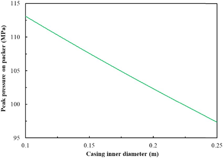
222 Hao Huang et al.
Figure 11: Influence of tubing length on peak pressure of the packer. Figure 12: Peak pressure on packer with different tubing lengths and
number of shock absorbers.
4 Field case study
The numerical model with shock absorbers can be used to
A deep-water well perforation case is used for the study, carry out simulation calculations. The peak perforating
and the length of the perforation gun section, rathole pressure on the packer under different tubing lengths
section, and perforated section are, respectively, 9, 10, with different number of shock absorbers can be obtained,
and 20 m. The rated working pressure of the packer is as shown in Figure 12.
70 MPa. The operation parameters of the deep-water field The figure reveals that with the increase in the
well are shown in Table 3. According to the prediction number of shock absorbers, the perforating peak pres-
model of perforation peak pressure on the packer of sure on the packer can be more reduced, by which the
equation (12), the peak pressure on the packer in the effect of shock-absorbing is better. As the tubing length
case can be calculated to be 105 MPa, which is beyond increases, the perforating peak pressure on the packer
the range of packer (70 MPa) and the packer will be decreases. If only one shock absorber is installed, the
damaged. safety of packer is still seriously threatened, which
When the material of the packer, the type of the per- cannot meet the safety requirements for deep-water per-
forated string, the number of perforating bullets and the foration operation. The minimum value of the perforating
single charge are fixed, increasing tubing length is a good peak pressure (73 MPa) on the packer still exceeds the
optimization measure, as shown in Figure 11. range of the packer (70 MPa). If the number of shock
In order to improve the safety of deep-water perfora- absorbers is two or three, the packer during deep-water
tion, the longitudinal shock absorbers are often installed perforating is safely combined with the optimization of
under the packer. Due to the complex environment tubing length. The color area in Figure 12 represents that
of deep-water wells, the shock absorbers of rubber com- the peak pressure on the packer during perforating is
ponents are often easily damaged, which brings great lower than the range of that, by which the safety of the
trouble to perforation operation. Therefore, the shock packer can be ensured.
absorbers of spring components are often used in the Based on the aforementioned analysis, the optimiza-
perforation of deep-water wells. Based on the numerical tion measure is put forward for perforation operation of
model established in Section 2, the shock absorbers are this deep-water well case. The tubing length is 16 m, and
simplified into spring elements and added into the model. three shock absorbers are installed in series in the
Table 3: Operation parameters
Casing inner diameter 0.22 m Tubing outer diameter 0.11 m
Perforating gun outer diameter 0.18 m Wellbore pressure 10 MPa
Number of perforating bullets 360 Single charge 40 g
Formation elastic modulus 1.27 GPa Formation pressure 12 MPa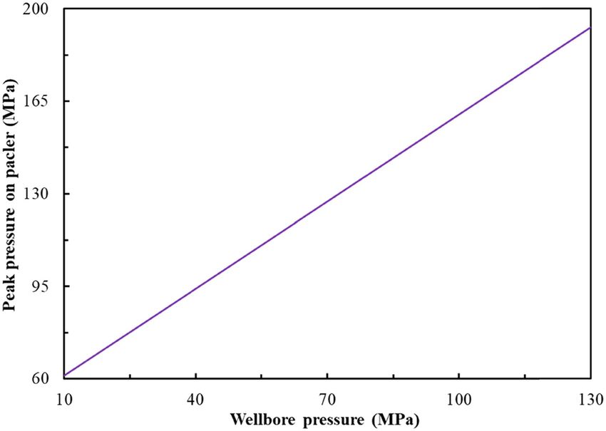
Study of dynamic pressure on the packer for deep-water perforation 223
perforated string. After perforation operation, the integ- Offshore technology conference, 30 April–3 May 2018,
rity of the packer is good with no damage or releasing. Houston, Texas, USA; 2018. p. 1–10.
[3] Eichelberger RJ. Experimental test of the theory of penetration
by metallic jets. J Appl Phys. 1956;27(1):63–8.
[4] Baumann CE, Bustillos EP, William A, Williams HAR. Reduction
5 Conclusion of perforating gunshock loads. Brasil offshore conference and
exhibition, 14–17 June 2011, Macaé, Brazil; 2011. p. 1–10.
[5] Baumann C, Dutertre A, Martin A, Williams H. Risk evaluation
The numerical model of the actual deep-water perfora- technique for tubing-conveyed perforating. Eage annual con-
tion has been established to study the dynamic perfor- ference & exhibition incorporating SPE Europec, Copenhagen,
ating pressure on the packer, and a series of numerical Denmark; 4–7 June, 2012. p. 33–45.
simulations have been carried out by using orthogonal [6] Canal AC, Miletto P, Schoener-Scott MF, Medeiros J, Barlow D.
Predicting pressure behavior and dynamic shock loads on
tests. The simulated result has been verified by the per-
completion hardware during perforating. Offshore technology
foration software, the database has been established, and conference; January, 2010. p. 125–38.
the model of the perforating peak pressure on the packer [7] Zhao X, Liu GH, Li J. Experimental study of the movement of control
has been fitted. The following conclusions can be obtained: fluid in compound perforation. Pet Sci. 2009;6(4):389–94.
1. Combining with the reflection and transmission of [8] Chen F, Chen H, Tang K. Influence of perforating impact load on
the operating string and the countermeasures. Nat Gas Ind.
shock waves on the packer during deep-water perfor-
2010;30(5):61–5.
ating, the prediction model of the perforating peak
[9] Sanders W, Baumann CE, Williams HAR, Moraes FD, Shipley J,
pressure on the packer has been obtained, which can Bethke ME. Efficient perforation of high-pressure deepwater
study the sensitivity of different factors. wells. Offshore technology conference, Houston, Texas, USA;
2. The analysis results show that the perforating peak 2–5 May, 2011. p. 22–36.
pressure on the packer peak is linearly related to the [10] Deng Q, Zhang H, Li J, Hou X, Wang H. Study of downhole shock
loads for ultra-deep well perforation and optimization mea-
wellbore pressure, has a logarithm function relation-
sures. Energies. 2019;12(14):2743.
ship with the number of perforating bullets and single [11] Lee WH. Oil well perforator design using 2D Eulerian code.
charge, and has an exponential function relationship Int J Impact Eng. 2002;27(5):535–59.
with the inner diameter of casing and tubing length. [12] Deng Q, Zhang H, Li J, Hou X, Zhao B. Numerical investigation
3. By the combination of increasing tubing length and of downhole perforation pressure for a deepwater well.
installing shock absorbers, the safety optimization mea- Energies. 2019;12(19):3795.
[13] Yan Y, Guan Z, Xu Y, Yan W, Wang H. Numerical investigation of
sures of perforation packer of deep-water wells are put
perforation to cementing interface damage area. J Pet Sci Eng.
forward. The case study shows that the effect is good. 2019;179:257–65.
[14] Liu J, Guo XQ, Liu ZJ, Liu X, Liu QY. Pressure field investigation
Acknowledgement: The authors gratefully acknowledge into oil & gas wellbore during perforating shaped charge
explosion. J Pet Sci Eng. 2019;172:1235–47.
the Natural Science Foundation of China (Grant Nos:
[15] Elshenawy T, Li QM. Influences of target strength and con-
U19B6003, 72001026, U19B6003-05, U1762211, 51734010, finement on the penetration depth of an oil well perforator.
51774063, 51774304, 51821092, and 51774063), the Strategic Int J Impact Eng. 2013;54:130–7.
Cooperation Technology Projects of CNPC and CUPB [16] Chen CY, Shiuan JH, Lan IF. The equation of state of detonation
(ZLZX2020-01), and the State Key Laboratory of Petroleum products obtained from cylinder expansion test. Propellants
Explos Pyrotech. 1994;19(1):9–14.
Resources and Engineering.
[17] LS-DYNA. Keyword user’s manual. vol. II, Version 971.
Livermore Software Technology, Livermore, CA, USA; 2013.
Conflict of interest: Authors state no conflict of interest. [18] Deng Q, Zhang H, Li J, Hou X, Wang H. Analysis of impact load
on tubing and shock absorption during perforating. Open
Phys. 2019;17:214–21.
[19] Qiu Q, Cui L. Optimal mission abort policy for systems subject
to random shocks based on virtual age process. Reliab Eng
References Syst Safe. 2019;189:11–20.
[20] Deng Q, Zhang H, Li J, Wang H, Cai ZX, Tan TY, et al. A model for
[1] Brockway PE, Owen A, Brand-Correa LI, Hardt L. Estimation of estimating penetration length under different conditions. 52nd
global final stage energy return-on-investment for fossil fuels US rock mechanics/geomechanics symposium, 17–20 June,
with comparison to renewable energy sources. Nat Energy. Seattle, Washington USA; 2018. p. 10–28.
2019;4(7):612–21. [21] Deng Q, Zhang H, Chen A, Li J, Hou X, Wang H. Effects of
[2] Deng Q, Zhang H, Li J, Dong J, Wang H, Hou XJ. Safety distances perforation fluid movement on downhole packer with shock
of packers for deep-water tubing-conveyed perforating. loads. J Pet Sci Eng. 2020;195:107566.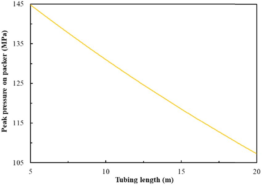
You can also read