Installation Guideline - Lindner Group
←
→
Page content transcription
If your browser does not render page correctly, please read the page content below
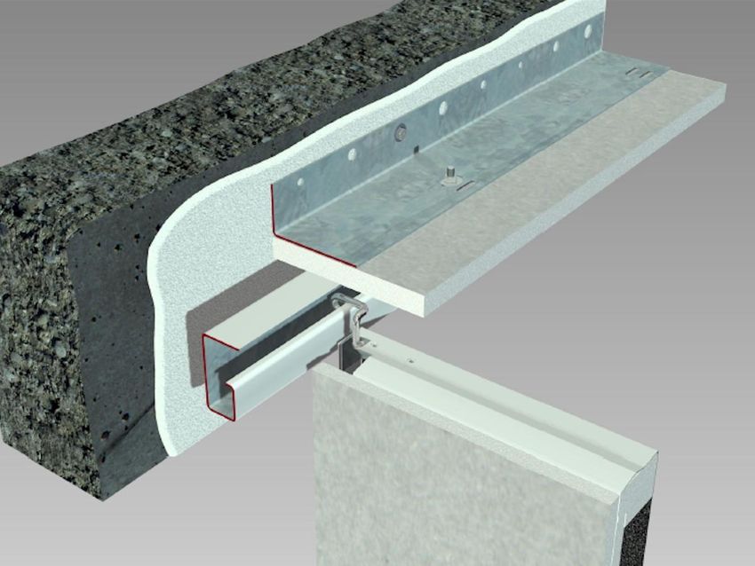
Installation Guideline
                                                                LMD F30-AB Type 7

LMD F30-AB Type 7

Fireproof ceilings according to DIN 4102-2
Elements Swing-Down/Slide Type
Standard installation

Illustration 1

LMD F30-AB Type 7              05.08.2021    Page 1 of 35            Rev.10         MR-PMD-F30ABT7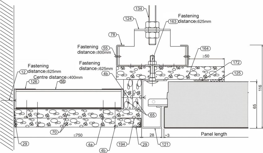
Installation Guideline
                                                                   LMD F30-AB Type 7

Index of contents
1.      Safety instructions                                                                         3
2.      Additional documents                                                                        3
3.      Preparation of installation                                                                 4
   3.1.    Constructional precondition                                                              4
   3.2.    Storage information/delivery of the material                                             5
   3.3.    Disposal of residual material                                                            5
   3.4.    Surface protection                                                                       6
4.      Structural condition for installation                                                       6
   4.1.    Partitions                                                                               6
   4.2.    Raw ceiling                                                                              7
   4.3.    Determining the type of fastening                                                        7
5.      Fixings                                                                                     8
   5.1.    Massive walls                                                                            8
   5.2.    Plasterboard partitions                                                                  8
   5.3.    Raw ceiling                                                                              8
6.      Longitudinal wall connection                                                                8
   6.1.    Straight wall connection                                                                 8
   6.2.    Determining the profile distance                                                         9
   6.3.    Determining distances of G-profile                                                      10
   6.4.    Installation of G-profile                                                               11
   6.5.    Installation of cover angle                                                             12
   6.6.    Inclined wall connection                                                                13
7.      Wall connection on the short side                                                          14
   7.1.    Installation of variant without shadow gap                                              14
   7.2.    Installation of variant with shadow gap                                                 15
8.      Installation of ceiling panels                                                             16
   8.1.    Hook-on procedure of metal ceiling elements                                             16
   8.2.    Swing-down procedure of metal ceiling elements                                          18
   8.3.    Removal of metal ceiling elements                                                       20
9.      Cut panels                                                                                 20
   9.1.    Preparation of cut panels                                                               20
10.     Centre suspension/Frieze connection                                                        21
   10.1. Suspension                                                                                21
   10.2. Installation process                                                                      22
   10.3. Centre suspension                                                                         23
   10.4. Centre suspension at corridor crossing                                                    24
   10.5. Elevated frieze connection, on the longitudinal side                                      26
   10.6. Elevated frieze connection, on the short side                                             27
   10.7. Level frieze connection, on the longitudinal side                                         29
   10.8. Level frieze connection, on the short side                                                31
11.     Installation of cable tray friezes                                                         32
12.     Constructions not covered by this installation guideline                                   32
13.     Declaration of compliance                                                                  33
14.     Checklist                                                                                  34

LMD F30-AB Type 7            05.08.2021        Page 2 of 35             Rev.10         MR-PMD-F30ABT7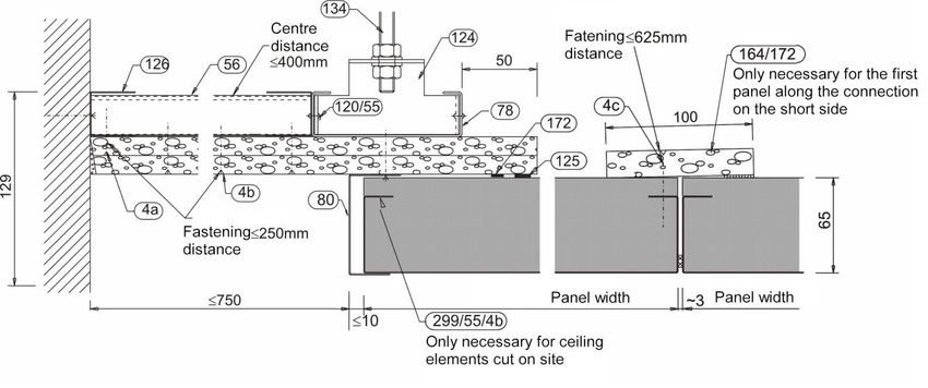
Installation Guideline
                                                                              LMD F30-AB Type 7

1. Safety instructions
       -    The installation has to be carried out with the necessary carefulness so that neither oneself nor
            another person is endangered by the installation and so that every other kind of damage is
            avoided
       -    Necessary measures concerning the security on site, e.g. barriers and protective equipment, have
            to be taken
       -    The national regulations for operational safety have to be regarded
       -    Handling of the heavy metal ceiling elements with caution, safety requirements according to the
            professional association guidelines have to be regarded.
       -    The fireproof ceiling may only be installed by qualified persons with the necessary technical
            knowledge, training, instructions and qualifications
       -    The assembly operation is fully liable for the conformity of the system
       -    Changes on the ceiling system or the use of foreign material cause variances of the technical
            characteristics of the metal ceilings and have to be agreed upon with the manufacturer
       -    A fireproof ceiling in properly installed and closed condition fulfils its function as fireproof ceiling!
       -    The plasterboard panels of the ceiling elements may not be damaged. They have to be in
            excellent condition. If this is not the case, please contact Lindner AG, department PM Ceilings.
       -    Other ceiling systems and combinations with other types of ceilings may only be used in
            accordance with the manufacturer
       -    Basically it is only allowed to use materials according to the corresponding manufacturer’s
            instructions
       -    The installation has to be carried out corresponding to this instruction. Variances have to be
            clarified with the manufacturer
       -    Fireproof ceilings are not adapted for the support of additional loads or for the fastening of
            partitions
       -    A distance of min. 50 mm has to be between the upper side of the fireproof ceiling (intermediate
            ceiling area) and the existing installations.
       -    After the installation, the declaration of compliance must have been completed by the assembler
            and transferred to the client.
       -    It is strongly recommended to fill out the check list for every component and to keep it with the
            documents for building structure

2. Additional documents
   Additional to this installation guideline, the following documents can be consulted if required:

   -       Installation Guideline F30 Überbrückungsträger Typ 100
   -       Installation Guideline Hohlraumdübel
   -       Installation Guideline Leuchten und sonstige Einbauten
   -       TAIM – Instructions for installation and application
   -       EN 13964
   -       DIN 4102-2

LMD F30-AB Type 7                  05.08.2021          Page 3 of 35                  Rev.10          MR-PMD-F30ABT7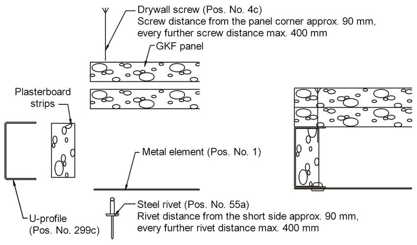
Installation Guideline
                                                                          LMD F30-AB Type 7

3. Preparation of installation

   3.1. Constructional precondition

       3.1.1.   Surroundings

       It is only allowed to start the installation of the metal ceilings if the room is dried and the facade is
       closed.
       It is the task of the client to make sure that the access to the construction site is sufficiently
       accessible for 40 t-vehicles.
       Only specifically authorised assembly personnel are allowed to open or close the ceiling until the
       approval of the ceiling. These assemblers have to possess specialised knowledge and appropriate
       tools.
       The client has to make sure that the place of installation is in close proximity provided with an
       appropriate location for stock and detrital container as well as an electrical connection.

       3.1.2.   Preface

       For the installation of metal ceilings, minimum requirements concerning structures, logistics,
       adjustment of the building services, environment, climate etc. have to be respected.
       To permit an orderly installation, certain basic prerequisites have to be secured before the assembly
       starts. These are not part of the scope of services of the Lindner AG or the installation company and
       have to be fulfilled by the client.
       Scopes of application and demands on metal ceilings are specified in the ‘TAIM’ guidelines (editor
       TAIM e.V.) and are met by Lindner metal ceilings, as far as nothing else is agreed upon. ‘TAIM’
       guidelines are available on demand.
       Requirements and applications which deviate from this, for example special requirements
       concerning security, special conditions of the operation and the climate, surfaces, additional loads,
       wind loads etc., have to be regarded by the client within his planning.

       3.1.3.   Benchmarks
                                                        Illustration 2
       Benchmarks of height and determination of
       axes have to be provided by the client. These
       have to be dimensioned in such a way that no
       measured lengths exceeding 30 m per storey
       will be necessary for the marking for the
       ceiling installation.

       3.1.4. Environmental conditions
       If no special specifications have been agreed
       upon, DIN EN 13964 and the environmental
       conditions mentioned in it are considered as
       agreed. It is only allowed to start the
       installation of the metal ceilings if the room is
       dried and the facade is closed Condensate
       formation in the ceiling void has to be obviated
       by the client. High humidity has to be
       subsequently obviated to avoid corrosion or
       mildew on mineral surfaces.
       As far as further demands occur due to the
       application in exterior areas, high air humidity
       or low strain of chloride, these have to be
       extensively specified and agreed upon.

LMD F30-AB Type 7               05.08.2021         Page 4 of 35                  Rev.10          MR-PMD-F30ABT7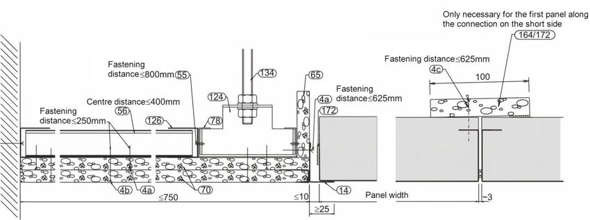
Installation Guideline
                                                                         LMD F30-AB Type 7

       3.1.5.   Integration of benchmarks and the handling of constructional tolerances on site

       Finished buildings and their benchmarks often diverge from their intended position according to the
       plan. It is advised to arrange such an inspection according to the national norms and rules, to create
       reflected ceiling plans and plans for the order, which are based on actually existing dimensions and
       to retain and evaluate discrepancies in measurement concerning the planning, ordering and
       installation of the ceiling at the earliest.
       It is possible that position and alignment of the facade pillars etc. do not exactly conform to the
       condition according to plan.
       In conjunction with the precise alignments of the metal ceilings this can appear visibly unpleasant
       and if it is disregarded it can result in complaints.
       Custom-fit, special panels or other measures may be reasonable.
       The consequences of the above-mentioned inspections, for example the direction of installation,
       definition of the alignments, position of custom-fit panels and so on, have to be detected and defined
       by the assembly operation in cooperation with the planner of the building and is not among the
       manufacturer’s area of responsibility.
       It is advised that the assembly operation notifies the planner of the building as soon as possible
       about discrepancies in measurement and that the assembly operation effects an approval for the
       solution that has to be realised.

   3.2. Storage information/delivery of the material
                                                        Illustration 3
   Please check all materials thoroughly for
   damages before the installation starts. We have to
   reject claims in an inbuilt condition.
   Do not store the metal panels outdoor and protect
   them against moisture and insolation!
   The fireproof panel packages have to be stored
   holohedral, even and dry.
   It is not allowed to stack them up.
   If a longer period of storage is planned, the
   manufacturer has to be previously asked.
   The following annotations concerning the
   protective foil have to be regarded.

   3.3. Disposal of residual material

   The disposal of metal ceiling waste does not pose an unusual threat with possibly sharp-edged
   components provided that the waste is handled with adequate care and appropriate personally
   well-fitting protective equipment is worn (for example protective gloves, safety shoes, helmet, safety
   glasses etc.).
   Fireproof ceilings do not contain harmful substances which endanger the health according to the
   guideline 67/548/EWG.
   Waste has to be disposed according to the respective regionally-binding regulations (for example the law
   of circular flow economy and the waste management law, packaging ordinance etc.).
   Basically it is not allowed to dispose construction waste, which is contaminated with harmful substances,
   at domestic refuse dumps. This construction waste has to be transported to facilities for special waste
   which are built for that purpose.
   Nationally and regionally-binding regulations have to be adhered to e.g. packaging ordinances, whereby
   all packages have to be returned to the economic cycle.
   Separation of waste generated on site is recommended to avoid collateral mixing. The separation of the
   waste generated on site has to be anticipated and has to be coordinated for each individual case.
   Regionally valid waste codes have to be respected.

LMD F30-AB Type 7             05.08.2021         Page 5 of 35                 Rev.10         MR-PMD-F30ABT7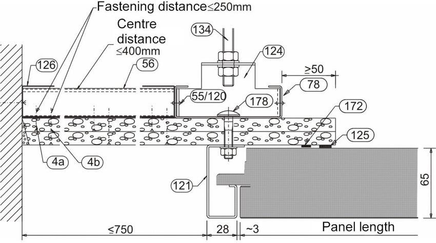
Installation Guideline
                                                                         LMD F30-AB Type 7

   3.4. Surface protection

       3.4.1.   Powder-coated ceiling panels

       To protect the surface, powder-coated ceiling panels are packaged back-to-back.
       Adjacent visible sides are protected against scratches by means of foam strips during the transport.
       These have to be removed before the installation of the panels.

       3.4.2.   Ceiling panels with protective foils

       To protect surfaces which are not powder-coated, the surfaces are furnished with protective foils.
       Steel sheet:
       The protective foil can be removed from steel sheet after 4 – 5 months after the delivery of the
       ceiling panels.
       Aluminium/stainless steel:
       With aluminium/stainless steel ceiling panels with transparent foil (not UV resistant), the foil should
       be removed within 4 weeks after delivery.
       With aluminium/high-grade steel ceiling panels with non-transparent foil, for example white or black
       (UV resistant), the foil should be removed within 3 months after delivery.
       Due to the influence of strong UV radiation (for example in the area of the facades) these periods
       can be shorter.
       Please notice that the expiration of this period may make it difficult to remove the foil properly and as
       a consequence of this, it may be possible that residues from the foil respectively adhesive will
       remain on the surface of the panels. In this case great cleaning effort has to be expected.
       For cleaning works the cleaning instructions have to be regarded.
       Please consult the manufacturer for the removal of adhesive residues with detergents.

4. Structural condition for installation

   4.1. Partitions

       Do the partitions to which the ceiling will be installed to                         Call the
                         have a proof ≥ F30?                              → no →           construction
                        Absolutely necessary!                                              management

                                   ↓
                                  yes
                                   ↓

      Are the partitions to which the ceiling will be installed to
                          sufficiently stable?
        Absolutely necessary is the load bearing capacity of:
                                                                                           Call the
     51 kg/lfm (element leng. 2500 mm, element width 400 mm)
                                                                          → no →           construction
                   load per side of a closed ceiling
                                                                                           management
              (without additional fixtures/installations),
      the expected extraction forces of the anchor have to be
                               respected!

                                   ↓
                                  yes
                                   ↓

            Shall the ceiling be fastened to massive walls
                                                                          → yes →          see part 4.2
                         concrete/stonework?

                                    ↓
                                   no
                                    ↓

LMD F30-AB Type 7               05.08.2021          Page 6 of 35                Rev.10         MR-PMD-F30ABT7
Installation Guideline
                                                                       LMD F30-AB Type 7

       Shall the ceiling be fastened to plasterboard partitions?        → yes →      see part 4.2

                                   ↓
                                  no
                                   ↓

     Shall the ceiling be fastened to other light weight partitions                  Call the
                                                                        → yes →
                            or bulkheads?                                            manufacturer

   4.2. Raw ceiling

                                                                                     Call the
              Does the raw ceiling have a proof ≥ F30?
                                                                        → no →       construction
                       Absolutely necessary!
                                                                                     management

                                   ↓
                                  yes
                                   ↓

                             see part 4.3

   4.3. Determining the type of fastening

                                                                                     Call the
          Is the structural condition for installation known?           → no →       construction
                                                                                     management

                                   ↓
                                  yes
                                   ↓

      Is the type of fastening and the fastening distance for the
                                                                                     Call the
           F30 construction that shall be installed available?          → no →
                                                                                     manufacturer
                         Absolutely necessary!

                                   ↓
                                  yes
                                   ↓

    If all conditions are met you can start with the installation of the ceiling system!

LMD F30-AB Type 7              05.08.2021          Page 7 of 35             Rev.10         MR-PMD-F30ABT7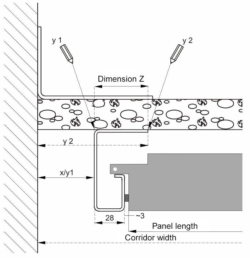
Installation Guideline
                                                                              LMD F30-AB Type 7

5. Fixings

Safety instruction :
   - The anchor has to be determined by the system manufacturer in individual cases depending on
        the load and the structural condition for installation.

   5.1. Massive walls

    Safety instructions:
       - Only anchors approved by ETA or a building authority may be used
       - The anchor has to be precisely fixed according to the instructions of the anchor manufacturer!

   5.2. Plasterboard partitions

    Safety instructions:
       - For the installation to plasterboard partitions special anchors with a test certificate have to be
            used!
       - The anchor has to be precisely fixed according to the instructions of the anchor manufacturer!
       - The installation to plasterboard partitions may only be executed in the metal substructure!
       - Use the installation guideline „Befestigung von Lindner-Metalldecken mit Brandschutzfunktion
            an GK-Wände“

   5.3. Raw ceiling

    Safety instructions:
       - The anchor must be a metal anchor with fire protection. Moreover, only anchors approved by
            ETA or a building authority may be used.
       - The anchor has to be precisely fixed according to the instructions of the anchor manufacturer!
       - When using anchors “Hilti Dübel HKD”, threaded rods have to be completely screwed in.

6. Longitudinal wall connection

   6.1. Straight wall connection

       6.1.1.   Materials

        Pos. No. 45/125/163/164/172           Pos. No. 4

        Wall connection                       TEKS/drywall screw black
        Standard adjusting range (00042188)   bugle head, cross recess
        completely, not pre-assembled         execution/length depending on
        L-angle, gasket strips, GKF strips    requirement
        fastening material

LMD F30-AB Type 7                05.08.2021           Page 8 of 35                 Rev.10         MR-PMD-F30ABT7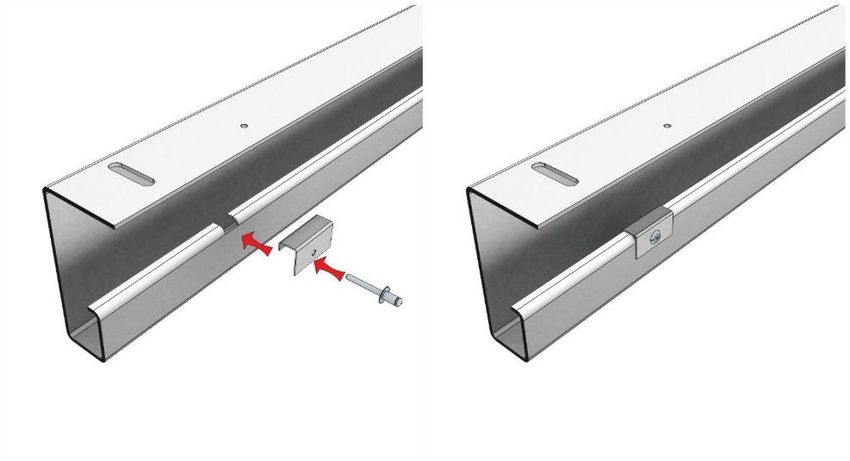
Installation Guideline
                                                                         LMD F30-AB Type 7

       6.1.2.   Installation process

       -   Level out the preset ceiling height and mark it circumferentially
       -   Mark the top edge of the perimeter trim (Pos. No. 45) (for example with a chalk line)
       -   Choose punched hole (appropriate hole diameter for determined anchor)
       -   Mark the location of the drill hole
       -   Drill a hole for the anchor and fix the perimeter trim (Pos. No. 45) with the anchor
       -   Fix the GKF strips (Pos. No. 164) alternatively with TEKS/SBS (Pos. No. 4)
       -   Close the GKF strip abutments and connections of GKF strips to partitions with a joint filler

       Illustration 4 (k17776)

                                                                      Ceiling height

   6.2. Determining the profile distance

       6.2.1.   Installation process

       -   Measure the corridor width at several points
       -   Determine the shadow gap = X,
           Attention: Pay regard to the tolerances of the corridor (mark an auxiliary line in the centre of the
           corridor)
       -   Check with ordered panel length if the adjusting range is sufficient

LMD F30-AB Type 7                05.08.2021        Page 9 of 35                 Rev.10          MR-PMD-F30ABT7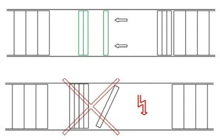
Installation Guideline
                                                                      LMD F30-AB Type 7

       Illustration 5 (k6289)

                                                                            →
        Attention:
                                                                       Dimension X
        Standard adjusting range                                                        Call the
                                                                      exceeding the
        if X < 12 mm                                                                    manufacturer
                                                                     adjusting range
        or X > 45 mm
                                                                            →

   6.3. Determining distances of G-profile

   Notice:
   - Depending on the installation procedure, y1 or y2 can be used for marking the position of hook-on
       profiles.

                                                     Illustration 6 (k12034)

        Attention:
        The following dimensions have to be
        measured on site:
        - corridor width
        - panel length
        - dimension Z

        y1 = (Fb – Pl – 62) / 2
           = x (joint)

        y2 = (Fb – Pl – 62) / 2 + dimension Z

       Fb = corridor width
       Pl = panel length

LMD F30-AB Type 7                 05.08.2021    Page 10 of 35                  Rev.10     MR-PMD-F30ABT7
Installation Guideline
LMD F30-AB Type 7
6.4. Installation of G-profile
6.4.1. Materials
Pos. No. 121 Pos. No. 163
G-profile Coach bolt M6 x 35 mm with nut M6
Depending on variant and washer
6.4.2. Installation process (first side)
- Mark the preset fastening distances
- Drill holes for coach bolts (Pos. No. 163) in the GKF strips
- Fix the G-profile (Pos. No. 121) alternatively with the delivered screws (Pos. No. 163)
- Install the G-profile (Pos. No. 121) flush aligned
Illustration 7 (k12034)
Front edge of the G-profile
= Panel length + 6 mm + 56 mm
Safety instruction:
- Distance between fixings every
312.5 mm. Use only the supplied
fastening screws (Pos. No. 163).
Washer must absolutely be
installed.
6.4.3. Installation process (second side)
- Mark the preset fastening distances
- Drill holes for coach bolts (Pos. No. 163) in the GKF strips
- Fix the 2. side of the G-profile (Pos. No. 121) parallelly aligned (installation template)
- Take distance fine adjustments
- Install and tighten all screws (Pos. No. 163) properly
- Close the GKF strip abutments with joint filler
- Make test loads or hook-on original elements
LMD F30-AB Type 7 05.08.2021 Page 11 of 35 Rev.10 MR-PMD-F30ABT7Installation Guideline
LMD F30-AB Type 7
6.5. Installation of cover angle
The installation of a cover angle is necessary if the hinging element of the ceiling panel is
positioned on the notch.
6.5.1. Material
Pos. No. 27 Pos. No. 789 Pos. No. 145a
G-profile Cover angle (00075851) Blind rivet (00027252)
6.5.2. Installation process installation of cover angle
- Mark the location of the drill hole with the cover angle (Pos. No. 789) on the G-profile (Pos. No.
27)
- Fasten the cover angle (Pos. No. 789) on the G-profile (Pos. No. 27) by means of a blind rivet
(Pos. No. 145a)
LMD F30-AB Type 7 05.08.2021 Page 12 of 35 Rev.10 MR-PMD-F30ABT7Installation Guideline
LMD F30-AB Type 7
6.6. Inclined wall connection
6.6.1. Material
Pos. No. 45/125/163/164/172 Pos. No. 200c Pos. No. 55a
Wall connection U-profile (00038750) Blind rivet (00027252)
Standard adjusting range (00042188) for inclined connections or shortened steel, SS-3006 FD, DIN 7337
completely, not pre-assembled ceiling elements
L-angle, gasket strips, GKF strips
fastening material
6.6.2. Installation process
- Install the L-angle (Pos. No. 45) and GKF strips (Pos. No. 164) as described in chapter 6.1
- Mark the preset fastening distances
- Drill holes for coach bolts (Pos. No. 163) in the GKF strips
- Install the U-profile (Pos. No. 200) flush aligned
- Take distance fine adjustments, take care of the minimum supporting surface of the ceiling
elements
- Install and tighten all screws (Pos. No. 163) properly
- Close the GKF strip abutments with joint filler
-
Illustration 8 (p16439)
Safety instruction:
- Every ceiling panel has to be
fastened with 2 rivets!
LMD F30-AB Type 7 05.08.2021 Page 13 of 35 Rev.10 MR-PMD-F30ABT7Installation Guideline
LMD F30-AB Type 7
7. Wall connection on the short side
7.1. Installation of variant without shadow gap
Safety instructions:
- Take care of the minimum supporting surface of the last ceiling panel.
- It is absolutely necessary to install a GKF cover strip (Pos. No. 164/172) above the last panel
joint.
7.1.1. Materials
Pos. No. 14 Pos. No. 164/172 Pos. No. 4
L-angle (00039288) Cover on the short side – end of the TEKS/drywall screw black
white corridor bugle head, cross recess
(00042183) execution/length depending on
completely pre-assembled requirement
GKF strip, gasket strip
7.1.2. Installation process
- Mark the top edge of the L-angle
- Install the L-angle (Pos. No. 14)
- Hook-on the ceiling element, take care of the minimum supporting surface
- If necessary, cut the ceiling element (Pos. No. 1) to the required width (chapter 9)
Illustration 9 (k10440)
LMD F30-AB Type 7 05.08.2021 Page 14 of 35 Rev.10 MR-PMD-F30ABT7Installation Guideline
LMD F30-AB Type 7
7.2. Installation of variant with shadow gap
Safety instructions:
- Take care of the minimum supporting surface of the last ceiling panel.
- It is absolutely necessary to install a GKF cover strip (Pos. No. 164/172) above the last panel
joint.
- If gasket strips are additionally fixed with hand tackers, the clamp may not penetrate the
gasket strip.
7.2.1. Materials
Pos. No. 45 Pos. No. 164 Pos. No. 80b
L-angle GKF strip U-profile (00037668)
sendzimir-galvanised for connection on the short side for connection on the short side
for connection on the short side
Pos. No. 164/172 Pos. No. 4 Pos. No. 125
Cover on the short side – end of the TEKS/drywall screw black Gasket strip (00044435)
corridor bugle head, cross recess
(00042183) execution/length depending on
completely pre-assembled requirement
GKF strip, gasket strip
Pos. No. 172
Gasket strip (00027711)
7.2.2. Installation process
- Install the L-angle (Pos. No. 45) and GKF strips (Pos. Nr. 164) as described in chapter 6.1
- Fix the GKF strips (Pos. No. 164) to the L-angle (Pos. No. 45) by means of TEKS/SBS (Pos. No.
4)
- Close the GKF strip abutments with joint filler
- Apply the gasket strips (Pos No. 125/172) on the plasterboard panel, fix it additionally with a hand
tacker if necessary
- Install the U-profile (Pos. No. 80b)
- Hook-on the ceiling element (Pos. No. 1), take care of the minimum supporting surface
- If necessary, cut the ceiling element (Pos. No. 1) to the required width (chapter 9)
calculation of U-profile length
length U-profile = panel length + 62mm (2 x 28 mm visible profile width + 2 x 3 mm joint)
LMD F30-AB Type 7 05.08.2021 Page 15 of 35 Rev.10 MR-PMD-F30ABT7Installation Guideline
LMD F30-AB Type 7
Illustration 10 (k5346)
8. Installation of ceiling panels
Safety instructions:
- Due to the high weight of metal ceiling elements, two persons are necessary to hook/unhook the
metal ceiling elements.
- Use only stable ladders or scaffolds.
- Do not deform or damage the metal ceiling elements during the hook-on procedure.
- In case of no slide protection, more than 3 ceiling elements can be moved together. This can
cause a ceiling crash.
- To avoid damages on the ceiling elements, it is necessary to slide the ceiling elements at an
angle of 90° to the G-profile.
8.1. Hook-on procedure of metal ceiling elements
Safety instruction:
- Is has to be ensured that ceiling elements are not hooked-on one-sided.
LMD F30-AB Type 7 05.08.2021 Page 16 of 35 Rev.10 MR-PMD-F30ABT7Installation Guideline
LMD F30-AB Type 7
Illustration 11 (k17774)
8.1.1. Material
Pos. No. 1 Pos. No. 667
Fireproof ceiling panel Cotton gloves Stopper (00036967)
as slide protection
Pos. Nr. 19b
Drilling screw (00027512)
ø4.2x13
8.1.2. Installation process
- Clean cotton gloves should be worn
- Lift the ceiling element (Pos. No. 1) to the G-profile (Pos. No. 121)
- Hook the ceiling element (Pos. No. 1) with the hinging hook on the notch of the G-profile
(Pos. No. 121)
- Maximum 3 swing-down type ceiling elements (Pos. No. 1) may be moved together
- Install the stopper (Pos. No. 667) as slide protection to the pre-drilled holes at the G-Profile
(Pos. No. 121) by means of a drilling screw (Pos. No. 19), maximum 3 ceiling elements (Pos. No.
1) may be between the stoppers.
- Lift the ceiling element (Pos. No. 1), push back the locking element
- Lift it slightly over the G-profile (Pos. No. 121), the locking element must audibly snap into place
- Adjust the distances of the G-profiles (Pos. No. 121) if necessary
- Tighten all screws (Pos. No. 163) properly
- Check the joint for rectangularity and a consistent width of 3 mm
LMD F30-AB Type 7 05.08.2021 Page 17 of 35 Rev.10 MR-PMD-F30ABT7Installation Guideline
LMD F30-AB Type 7
Illustration 12 Illustration 13 (k17774)
Illustration 14 (k15744) Illustration 15 (k12034)
8.2. Swing-down procedure of metal ceiling elements
Safety instructions:
- In case of no slide protection, more than 3 ceiling elements can be moved together. This can
cause a ceiling crash.
- To avoid damages on the ceiling elements, it is necessary to slide the ceiling elements at an
angle of 90° to the G-profile.
LMD F30-AB Type 7 05.08.2021 Page 18 of 35 Rev.10 MR-PMD-F30ABT7Installation Guideline
LMD F30-AB Type 7
8.2.1. Material
Pos. No. 410
Operating tool (00032922) Cotton gloves
Spatula
8.2.2. Installation process
- Clean cotton gloves should be worn
- Lift the ceiling element (Pos. No. 1) slightly
- Push the operating tool (Pos. No. 410) in the joint between the G-profile (Pos. No. 121) and the
ceiling element (Pos. No. 1)
- Push back the locking element with the operating tool (Pos. No. 410)
- Lower the ceiling element (Pos. No. 1)
- Repeat the same process on the opposite G-profile (Pos. No. 121)
- Lower and slide the ceiling element with caution, maximum 3 ceiling elements may be moved
together
Illustration 16 (k5206) Illustration 17 (k12034)
Illustration 18 (k17774)
LMD F30-AB Type 7 05.08.2021 Page 19 of 35 Rev.10 MR-PMD-F30ABT7Installation Guideline
LMD F30-AB Type 7
8.3. Removal of metal ceiling elements
8.3.1. Removal process
- Clean cotton gloves should be worn
- Move the ceiling element (Pos. No. 1) with the hinging hook to the notch of the G-profile (Pos.
No. 121)
- Lift the ceiling element (Pos. No. 1) over the notch of the G-profile (Pos. No. 121)
- Lower the ceiling element (Pos. No. 1) with caution and store it secure from damages
Illustration 19
9. Cut panels
9.1. Preparation of cut panels
Notice:
- Due to the rivet, a joint exists between support bracket, U-profile and metal ceiling element.
9.1.1. Material
Pos. No. 299 Pos. No. 4 Pos. No. 55a
U-profile (00040296) TEKS/drywall screw black Blind rivet (00027252)
For cut panels bugle head, cross recess steel, SS-3006 FD, DIN 7337
execution/length depending on
requirement
LMD F30-AB Type 7 05.08.2021 Page 20 of 35 Rev.10 MR-PMD-F30ABT7Installation Guideline
LMD F30-AB Type 7
9.1.2. Installation process
- Transfer the necessary cutting measures on the metal ceiling element (Pos. No. 1)
- Cut the metal ceiling element (Pos. No. 1) by means of a compass saw
- Prepare the plasterboard strip and insert it in the U-profile (Pos. No. 299c)
- Move the U-profile (Pos. No. 299c) to the edge between the metal ceiling element (Pos. No. 1)
and the GKF panel
- Screw the U-profile (Pos. No. 299c) from above through the GKF panel by means of TEKS/SBS
(Pos. No. 4) and rivet it from below through the metal ceiling element by means of steel rivets
(Pos. No. 55a)
Illustration 20 (k13204)
10. Centre suspension/Frieze connection
Safety instruction:
- The anchor, the dimensioning and the distance of threaded rods must be determined by the
system manufacturer in individual cases depending on the load and the structural condition for
installation.
- Max. distance of fastening ≤ 800 mm
- First hanger is to be placed in the area ≤ 100 mm.
10.1. Suspension
10.1.1. Suspension with threaded rods
Notice:
- Suspension by means of minimum M8 threaded rods.
- Maximum hanger distance 800 mm.
LMD F30-AB Type 7 05.08.2021 Page 21 of 35 Rev.10 MR-PMD-F30ABT7Installation Guideline
LMD F30-AB Type 7
10.1.2. Material
Pos. No. 134
Anchor Threaded rod
Type depending on structural Ø depending on static requirement
condition for installation
10.2. Installation process
- Mark and drill a hole for the anchor
- Install the admissible anchor according to manufacturer’s instructions
- Cut the threaded rod (Pos. No. 134) to the required suspension height and screw it to the anchor
until the stop.
Illustration 21 (p15522)
LMD F30-AB Type 7 05.08.2021 Page 22 of 35 Rev.10 MR-PMD-F30ABT7Installation Guideline
LMD F30-AB Type 7
10.3. Centre suspension
Notice:
- Do not hook-on the ceiling elements until all screws are installed and tightened properly.
10.3.1. Material
Pos. No. 125, 128, 163, 164, 172 Pos. No. 121 Pos. No. 55a
Centre suspension (00042197) G-profile Blind rivet (00027252)
completely, not pre-assembled Depending on variant steel, SS-3006 FD, DIN 7337
C-post cap, GKF strips, fastening
material, gasket strips
Pos. No. 124 Pos. No. 134 Pos. No. 4
Post cap hanger Hexagonal nut and washer TEKS/drywall screw black
depending on static requirement depending on static requirement bugle head, cross recess
execution/length depending on
requirement
10.3.2. Installation Process
- Fix the C-post cap (Pos. No. 128) with the post cap hanger (Pos. No. 124) on the threaded rod
(Pos. No. 134) by means of hexagonal nut and washer (Pos. No. 134)
- Level out the post cap height (Pos. No. 128) according to the preset ceiling height
- Fix the post cap hanger (Pos No. 124) on the post cap (Pos. No. 128) by means of steel rivets
(Pos. No. 55) on both sides
- Fix the GKF strips (Pos. No. 164) alternatively by means of TEKS/SBS (Pos. No. 4)
- Close abutments of GKF strips (Pos. No. 164) by means of joint filler
- Mark the preset fastening distances
- Drill holes for screw connections
- Fix the G-profile (Pos. No. 121) alternatively with the delivered screws (Pos. No. 163)
- Install the G-profile (Pos. No. 121) flush aligned
- Take distance fine adjustments
- Tighten all screws (Pos. No. 163) properly
LMD F30-AB Type 7 05.08.2021 Page 23 of 35 Rev.10 MR-PMD-F30ABT7Installation Guideline
LMD F30-AB Type 7
Illustration 22 (k5762)
10.4. Centre suspension at corridor crossing
Safety instructions:
- Take care of the minimum supporting surface of the last ceiling panel.
- It is absolutely necessary to install a GKF cover strip (Pos. No. 164/172) above the last panel
joint.
Notice:
- Do not hook-on the ceiling elements until all screws are installed and tightened properly.
LMD F30-AB Type 7 05.08.2021 Page 24 of 35 Rev.10 MR-PMD-F30ABT7Installation Guideline
LMD F30-AB Type 7
10.4.1. Material
Pos. No. 125, 128, 163, 164, 172 Pos. No. 121 Pos. No. 55a
Centre suspension (00042187) G-profile Blind rivet (00027252)
completely, not pre-assembled depending on variant steel, SS-3006 FD, DIN 7337
C-post cap, GKF strips, fastening
material, gasket strips
Pos. No. 124 Pos. No. 134 Pos. No. 80b
Post cap hanger Hexagonal nut and washer U-profile (00037668)
depending on static requirement depending on static requirement for connection on the short side
Pos. No. 164/172 Pos. No. 4
Cover on the short side – end of the TEKS/drywall screw black
corridor bugle head, cross recess
(00042183) execution/length depending on
completely pre-assembled requirement
GKF strip, gasket strip
10.4.2. Installation process
- Fix the C-post cap (Pos. No. 128) with the post cap hanger (Pos. No. 124) on the threaded rod
(Pos. No. 134) by means of hexagonal nut and washer (Pos. No. 134)
- Level out the post cap height (Pos. No. 128) according to the preset ceiling height
- Fix the post cap hanger (Pos No. 124) on the post cap (Pos. No. 128) by means of steel rivets
(Pos. No. 55) on both sides
- Fix the GKF strips (Pos. No. 164) alternatively by means of TEKS/SBS (Pos. No. 4)
- Close abutments of GKF strips (Pos. No. 164) by means of joint filler
- Mark the preset fastening distances
- Drill holes for screw connections
- Fix the G-profile (Pos. No. 121) alternatively with the delivered screws (Pos. No. 163)
- Install the U-profile (Pos. No. 80) flush aligned by means of TEKS/SBS (Pos. No. 4)
- Install the G-profile (Pos. No. 121) flush aligned with the U-profile (Pos. No. 80)
- Take distance fine adjustments
- Tighten all screws properly
LMD F30-AB Type 7 05.08.2021 Page 25 of 35 Rev.10 MR-PMD-F30ABT7Installation Guideline
LMD F30-AB Type 7
Illustration 23 (k5865)
10.5. Elevated frieze connection, on the longitudinal side
Safety instructions:
- If gasket strips are additionally fixed with hand tackers, the clamp may not penetrate the
gasket strip.
Notice:
- Do not hook-on the ceiling elements until all screws are installed and tightened properly.
10.5.1. Material
Pos. No. 78, 125, 172, 178 Pos. No. 121 Pos. No. 124
Connection to plasterboard frieze G-profile Post cap hanger
(00042204) depending on variant depending on static requirement
completely, not pre-assembled
C-post cap, fastening material, gasket
strips, GKF panels on site
Pos. No. 56 Pos. No. 126
GKF panels 12.5 mm Suspension channel U-profile
Pos. No. 134 Pos. No. 55a Pos. No. 4
Hexagonal nut and washer Blind rivet (00027252) TEKS/drywall screw black
depending on static requirement steel, SS-3006 FD, DIN 7337 bugle head, cross recess
execution/length depending on
requirement
LMD F30-AB Type 7 05.08.2021 Page 26 of 35 Rev.10 MR-PMD-F30ABT7Installation Guideline
LMD F30-AB Type 7
10.5.2. Installation process
- Fix the C-post cap (Pos. No. 78) with the post cap hanger (Pos. No. 124) on the threaded rod
(Pos. No. 134) by means of hexagonal nut and washer (Pos. No. 134)
- Level out the post cap height (Pos. No. 78) according to the preset ceiling height
- Fix the post cap hanger (Pos No. 124) on the post cap (Pos. No. 78) by means of steel rivets
(Pos. No. 55) on both sides
- Install the plasterboard frieze according to the general building regulations test certificate (AbP),
screw the plasterboard panels in the UD-profile (Pos. 126)
- Close abutments of the plasterboard frieze by means of joint filler
- Apply the gasket strips (Pos No. 125/172) on the plasterboard panel, fix it additionally with a hand
tacker if necessary
- Mark the preset fastening distances
- Drill holes for screw connections
- Fix the G-profile (Pos. No. 121) alternatively with the delivered screws (Pos. No. 163)
- Install the G-profile (Pos. No. 121) flush aligned
- Take distance fine adjustments
- Tighten all screws (Pos. No. 163) properly
Illustration 24 (k5782)
10.6. Elevated frieze connection, on the short side
Safety instructions:
- Take care of the minimum supporting surface of the last ceiling panel.
- It is absolutely necessary to install a GKF cover strip (Pos. No. 164/172) above the last panel
joint.
- If gasket strips are additionally fixed with hand tackers, the clamp may not penetrate the
gasket strip.
Notice:
- Do not hook-on the ceiling elements until all screws are installed and tightened properly.
LMD F30-AB Type 7 05.08.2021 Page 27 of 35 Rev.10 MR-PMD-F30ABT7Installation Guideline
LMD F30-AB Type 7
10.6.1. Material
Pos. No. 78, 125, 172, 178 Pos. No. 80b Pos. No. 124
Connection to plasterboard frieze U-profile (00037668) Post cap hanger
(00042204) for connection on the short side depending on static requirement
completely, not pre-assembled
C-post cap, fastening material, gasket
strips, GKF panels on site
Pos. No. 56 Pos. No. 126
GKF panels 12.5 mm Suspension channel U-profile
Pos. No. 164/172 Pos. No. 4 Pos. No. 134
Cover on the short side – end of the TEKS/drywall screw black Hexagonal nut and washer
corridor bugle head, cross recess depending on static requirement
(00042183) execution/length depending on
completely pre-assembled requirement
GKF strip, gasket strip
Pos. No. 55a
Blind rivet (00027252)
steel, SS-3006 FD, DIN 7337
10.6.2. Installation process
- Fix the C-post cap (Pos. No. 78) with the post cap hanger (Pos. No. 124) on the threaded rod
(Pos. No. 134) by means of hexagonal nut and washer (Pos. No. 134)
- Level out the post cap height (Pos. No. 78) according to the preset ceiling height
- Fix the post cap hanger (Pos No. 124) on the post cap (Pos. No. 78) by means of steel rivets
(Pos. No. 55) on both sides
- Install the plasterboard frieze according to the general building regulations test certificate (AbP),
screw the plasterboard panels in the UD-profile (Pos. 126)
- Close abutments of the plasterboard frieze by means of joint filler
- Apply the gasket strips (Pos No. 125/172) on the plasterboard panel, fix it additionally with a hand
tacker if necessary
- Install the U-profile (Pos. No. 80) flush aligned by means of TEKS/SBS (Pos. No. 4)
- Tighten all screws properly
LMD F30-AB Type 7 05.08.2021 Page 28 of 35 Rev.10 MR-PMD-F30ABT7Installation Guideline
LMD F30-AB Type 7
Illustration 25 (k18143)
10.7. Level frieze connection, on the longitudinal side
Safety instructions:
- If gasket strips are additionally fixed with hand tackers, the clamp may not penetrate the
gasket strip.
Notice:
- Do not hook-on the ceiling elements until all screws are installed and tightened properly.
10.7.1. Material
Pos. No. 65, 78, 125, 163, 164, 172 Pos. No. 121 Pos. No. 124
Connection to plasterboard frieze G-profile Post cap hanger
completely, not pre-assembled depending on variant depending on static requirement
C-post cap, GKF strips fastening
material, gasket strips
Pos. No. 65/70 Pos. No. 56 Pos. No. 126
GKF panels 12.5 mm on site Suspension channel U-profile
Pos. No. 134 Pos. No. 55a Pos. No. 4
Hexagonal nut and washer Blind rivet (00027252) TEKS/drywall screw black
depending on static requirement steel, SS-3006 FD, DIN 7337 bugle head, cross recess
execution/length depending on
requirement
LMD F30-AB Type 7 05.08.2021 Page 29 of 35 Rev.10 MR-PMD-F30ABT7Installation Guideline
LMD F30-AB Type 7
10.7.2. Installation process
- Fix the C-post cap (Pos. No. 78) with the post cap hanger (Pos. No. 124) on the threaded rod
(Pos. No. 134) by means of hexagonal nut and washer (Pos. No. 134)
- Level out the post cap height (Pos. No. 78) according to the preset ceiling height
- Install the GKF strips (Pos. No. 164) alternatively by means of TEKS/SBS (Pos. No. 4)
- Close abutments of the GKF strips (Pos. No. 164) by means of joint filler
- Apply the gasket strips (Pos No. 125/172) on the plasterboard panel, fix it additionally with a hand
tacker if necessary
- Mark the preset fastening distances
- Drill holes for screw connections
- Fix the G-profile (Pos. No. 121) alternatively with the delivered screws (Pos. No. 163)
- Install the G-profile (Pos. No. 121) flush aligned
- Fix the GKF strips (Pos. No. 65) on the G-profile (Pos. No. 121) by means of TEKS/SBS (Pos.
No. 4)
- Install the plasterboard frieze according to the general building regulations test certificate (AbP),
screw the plasterboard panels in the UD-profile (Pos. No. 126)
- Close abutments of the plasterboard frieze and the GKF strips by means of joint filler
- Take distance fine adjustments
- Tighten all screws properly
Illustration 26 (K10065)
LMD F30-AB Type 7 05.08.2021 Page 30 of 35 Rev.10 MR-PMD-F30ABT7Installation Guideline
LMD F30-AB Type 7
10.8. Level frieze connection, on the short side
Safety instructions:
- Take care of the minimum supporting surface of the last ceiling panel.
- Install the last ceiling panel with a gasket strip.
- It is absolutely necessary to install a GKF cover strip (Pos. No. 164/172) above the last panel
joint.
Notice:
- Do not hook-on the ceiling elements until all screws are installed and tightened properly.
10.8.1. Material
Pos. No. 65 Pos. No. 14 Pos. No. 124
GKF strips 12.5 mm L-angle Post cap hanger
Depending on variant depending on static requirement
Pos. No. 56 Pos. No. 126
GKF panels 12.5 mm on site Suspension channel U-profile
Pos. No. 164/172 Pos. No. 4 Pos. No. 134
Cover on the short side – end of the TEKS/drywall screw black Hexagonal nut and washer
corridor bugle head, cross recess depending on static requirement
(00042183) execution/length depending on
completely pre-assembled requirement
GKF strip, gasket strip
Pos. No. 55a Pos. No. 172
Blind rivet (00027252) Gasket strip (00027711)
steel, SS-3006 FD, DIN 7337
LMD F30-AB Type 7 05.08.2021 Page 31 of 35 Rev.10 MR-PMD-F30ABT7Installation Guideline
LMD F30-AB Type 7
10.8.2. Installation process
- Fix the C-post cap (Pos. No. 78) with the post cap hanger (Pos. No. 124) on the threaded rod
(Pos. No. 134) by means of hexagonal nut and washer (Pos. No. 134)
- Level out the post cap height (Pos. No. 78) according to the preset ceiling height
- Fix the post cap hanger (Pos No. 124) on the post cap (Pos. No. 78) by means of steel rivets
(Pos. No. 55) on both sides
- Install the plasterboard frieze according to the general building regulations test certificate (AbP),
screw the plasterboard panels in the UD-profile (Pos. 126)
- Fix the GKF strip (Pos. No. 65) on the short side by means of a drywall screw (Pos. No. 4)
- Close abutments of the plasterboard frieze and the GKF strips by means of joint filler
- Install the L-angle (Pos. No. 14) flush aligned by means of TEKS/SBS (Pos. No. 4)
Illustration 27 (k18152)
11. Installation of cable tray friezes
Cable tray friezes may only be executed in coordination with the system manufacturer. Separate installation
guidelines have to be requested.
12. Constructions not covered by this installation guideline
Constructions not covered by this installation guideline, other types of ceilings and combinations of different
ceiling types may only be executed after consulting the manufacturer.
LMD F30-AB Type 7 05.08.2021 Page 32 of 35 Rev.10 MR-PMD-F30ABT7Installation Guideline
LMD F30-AB Type 7
13. Declaration of compliance
Declaration of compliance of the user
Name and address of the company that produced/installed the suspended ceiling
Building site resp. building:
Date of installation:
Ceiling system: F30-AB Type 7
Fire resistance class F30 from: above/below
It is herewith confirmed that the suspended ceiling construction of the fire resistance class F30 was
produced and installed professionally regarding all details and in compliance with all regulations of the
general building regulations test certificate No. P-SAC-02/III-596 by the material test establishment for
building industry, Leipzig, dated 21.06.2013.
No further details, installations resp. fixtures and connections differing from the above-named test certificate
were executed. (In case of deviations, they have to be described and proven with a fire protection proof, e.g.
a site-related report.)
To ensure this, the regulations of the installation guidelines named by the manufacturer were obeyed.
This is also confirmed for building products or component parts that were not produced by the subscriber
itself due to:
Corresponding written confirmations of the manufacturer of the building products and parts which are filed
away by the subscriber
A declaration of compliance of the manufacturer of the suspended ceiling (Prefabrication of the
components)
Place; date Stamp and signature of the installer
This confirmation has to be handed over to the client for transmission to the responsible building supervisory
authority.
LMD F30-AB Type 7 05.08.2021 Page 33 of 35 Rev.10 MR-PMD-F30ABT7Installation Guideline
LMD F30-AB Type 7
14. Checklist
For your own assurance it is recommended to fill out and retain a checking card for every component.
BV: Plane: Component: Axes:
Bulkhead by C-p. c.
M. honeyc. baffle c.
Project number
Metal ceiling F30
Metal ceiling F90
Plafotherm® Heated
Metal ceiling F0
and chilled ceiling
Type of accomplishment
OK Date Inspected by:
Mark the achieved accomplishment with a „X“
Ceiling height and cutting check verified
Suspension distance maintained and checked distance: mm
Approved anchor used for application and existing base material type:
Anchor visually checked for correct installation
Rough grate / post cap / dimension between axes maintained and checked
distance: mm
Precision grate / lateral carrier section / dimension between axes maintained
distance: mm
Mineral wool platings inserted correctly and checked
Nearby connections achieved and checked according to detail
Built-in components additionally suspended from the raw ceiling and checked
according to the declaration of the PL
Installation guidelines of the producer maintained
Material storing checked
Cut panels in the perimeter checked according to the correct cutting
Fastening clamp inserted correctly
Centre/frieze suspension mounted correctly according to the declaration of the PL
Function of the ceiling panels checked
Ceiling surface with the same colour, exactly aligned, without soiling
For the bulkhead by C-p. c: Necessary bracing mounted acc. to requirements
Signature PL: Signature BL/VA:
(Only for confirmation, unless the PL himself inspects)
LMD F30-AB Type 7 05.08.2021 Page 34 of 35 Rev.10 MR-PMD-F30ABT7Installation Guideline
LMD F30-AB Type 7
This recommendation shall serve as a guideline to the assembler.
The application always has to be examined in individual cases due to the fact that no site-related inspection occurred.
The details given therein represent the state-of-the-art and shall inform about our products and their field of application. They are given
to the best of our knowledge. No responsibility is taken for the correctness of the information given in this guideline. The relevant
standards especially DIN EN 13964 as well as the TAIM standards shall be considered.
Subject to technical alteration in the course of progress.
Drawings and Illustrations are illustrative.
All rights reserved.
Contact:
Lindner SE | Ceilings
Bahnhofstraße 29 | 94424 Arnstorf | Germany
Phone +49 8723 20-3679
ceilings@Lindner-Group.com | www.Lindner-Group.com
Publisher:
Lindner SE | PM Ceilings
Bahnhofstraße 29 | 94424 Arnstorf | Germany
LMD F30-AB Type 7 05.08.2021 Page 35 of 35 Rev.10 MR-PMD-F30ABT7You can also read