Sigfox connected objects: Radio specifications - February 2019 - OVH.net
←
→
Page content transcription
If your browser does not render page correctly, please read the page content below
Sigfox connected objects:
Radio specifications

February 2019

Ref.: EP-SPECS
                                                     Sigfox connected objects                     Rev.: 1.3
                                                        Radio specifications
                                                                                                  Date: Feb. 2019

                                                  Terms of use

These terms of use (the “Terms”) issued by SIGFOX SA (“SIGFOX”) governs your use of this document entitled “Sigfox
connected objects - radio specifications” and its content (the “Document”). These Terms shall be governed by the laws
of France.

You acknowledge that you have read, understood and agree to be bound by all of the terms and conditions set forth
in these Terms. If you do not agree to the Terms, do not use this Document.

For the purpose of these Terms, (i) “Product” means an end-device or end-point or wireless transmit/receive unit (WTRU)
including, but not limited to, a user equipment, a sensor, an actuator, a fixed or mobile subscriber unit, a cellular
telephone, a computer, or any other type of end-device capable of operating in a wireless environment, enabling access
to the SIGFOX Network; and (ii) “SIGFOX Network” means the radio access network and associated network
infrastructure designed by SIGFOX.

SIGFOX owns and retains all proprietary rights, title and interest, including all intellectual property rights in and to the
Document. You acknowledge that the rights granted under these Terms do not provide you with title to or ownership
on the Document, but only a right of limited use in accordance with these Terms.

Subject to these Terms, SIGFOX grants you a limited, non-exclusive, non-transferable, worldwide, royalty-free right to
use the Document, during the whole duration of legal protection by intellectual property rights of the Document, solely
to the extent necessary to develop a Product to be connected to the SIGFOX Network and/or for academic, educational
purposes to discover, promote, improve Sigfox technology. Any other use is strictly prohibited.

Please note that you may not sell, make available for sale, or otherwise distribute any Product, unless and until such
Product (a) embeds the applicable authentication credentials (to be generated and provided by SIGFOX) and (b) has
been SIGFOX certified (such certification is subject to the terms and conditions of the SIGFOX’s certification program).

You shall not (a) modify the document or create any derivative work of any part of the Document; (b) use the Document
in any way that would not be in compliance with these Terms or with applicable laws or regulations; (c) develop any
Product that exploits or creates vulnerabilities in SIGFOX Network, introduces in SIGFOX Network any virus, worm,
Trojan horse or similar harmful or malicious code, or otherwise harms SIGFOX Network; (d) remove or attempt to
remove any SIGFOX trademark, logo or copyright notice displayed on the Document.

THIS DOCUMENT IS PROVIDED TO YOU FOR FREE, ON AN “AS IS” AND “AS AVAILABLE” BASIS. SIGFOX MAKES NO
WARRANTIES, EXPRESS, IMPLIED, STATUTORY, OR OTHERWISE, WITH RESPECT TO THIS DOCUMENT OR ITS CONTENT.
SIGFOX SPECIFICALLY DISCLAIMS THE WARRANTIES OF MERCHANTABILITY, FITNESS FOR A PARTICULAR PURPOSE AND
NON-INFRINGEMENT AND THOSE ARISING FROM A COURSE OF DEALING OR USAGE OR TRADE, AND ALL SUCH
WARRANTIES ARE HEREBY EXCLUDED TO THE FULLEST EXTENT PERMITTED BY APPLICABLE LAWS.

THE CONTENT OF THE DOCUMENT IS PROVIDED ON AN INDICATIVE BASIS. IN NO EVENT SIGFOX SHALL BE LIABLE FOR
THE RELIABILITY, EFFECTIVENESS OR COMPLETENESS OF THE INFORMATION CONTAINED IN THIS DOCUMENT. TO THE
MAXIMUM EXTENT PERMITTED BY APPLICABLE LAW, In no event shall SIGFOX be liable under THESE TERMS for
consequential, special, exemplary, or any OTHER indirect (including without limitation, lost profits, loss of records or
data) DAMAGES regardless of whether arising from breach of contract, warranty, tort, strict liability, or otherwise, even
if advised of the possibility of the loss or damage or if the loss or damage could have been reasonably foreseen.

EP-SPECS                                     © copyright Sigfox - all rights reserved                            Page 2 of 36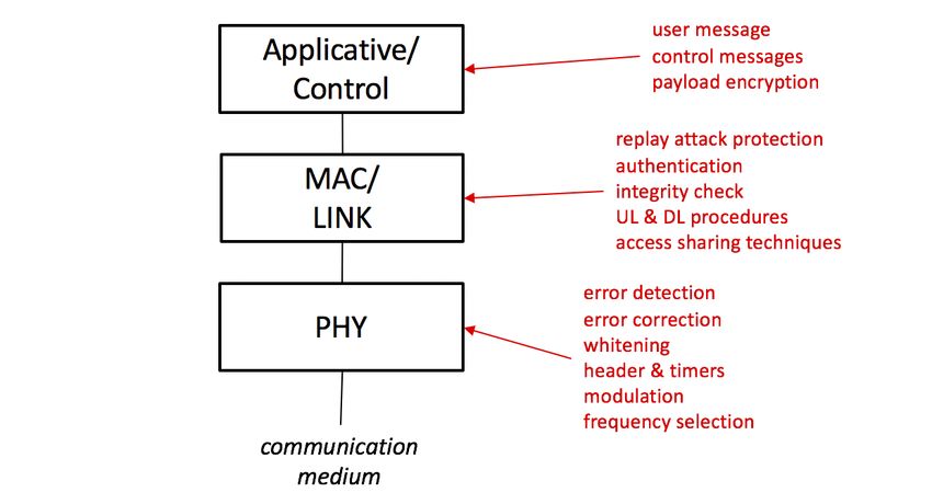
Ref.: EP-SPECS
                                                                          Sigfox connected objects                                           Rev.: 1.3
                                                                             Radio specifications
                                                                                                                                             Date: Feb. 2019

                                                                  Table of content

1     INTRODUCTION ................................................................................................................................................4
2     RADIO HARDWARE ENGINEERING ....................................................................................................................5
    2.1       LOCAL REGULATION CONSTRAINTS............................................................................................................................ 5
    2.2       MACRO- AND MICRO- CHANNELS ............................................................................................................................. 6
    2.3       SYMBOL RATES ..................................................................................................................................................... 7
    2.4       END-POINT TX CHARACTERISTICS ............................................................................................................................. 8
    2.5       END-POINT RX CHARACTERISTICS ........................................................................................................................... 11
3     UPLINK PROTOCOL ENGINEERING ................................................................................................................... 13
    3.1       UPLINK FRAME CONSTRUCTION OVERVIEW .............................................................................................................. 13
    3.2       UPLINK MESSAGE CONTENT .................................................................................................................................. 13
    3.3       LENGTH INDICATOR (LI) ....................................................................................................................................... 14
    3.4       BIDIRECTIONAL FRAG (BF) ................................................................................................................................... 14
    3.5       REPEATED FLAG (REP) ........................................................................................................................................ 14
    3.6       MESSAGE COUNTER (MC) ................................................................................................................................... 14
    3.7       IDENTIFIER (ID) .................................................................................................................................................. 14
    3.8       UPLINK AUTHENTICATION (UL-AUTH)................................................................................................................... 15
    3.9       UPLINK ERROR DETECTION FIELD (UL-CRC) ............................................................................................................. 16
    3.10      UPLINK CONVOLUTIONAL CODING FUNCTION ............................................................................................................ 16
    3.11      UPLINK FRAME TYPE (FT) ..................................................................................................................................... 17
    3.12      UPLINK PREAMBLE (UL-PR) .................................................................................................................................. 18
    3.13      UPLINK PROCEDURE ............................................................................................................................................ 18
4     DOWNLINK PROTOCOL ENGINEERING ............................................................................................................ 20
    4.1       DOWNLINK FRAME CONSTRUCTION OVERVIEW ......................................................................................................... 20
    4.2       DOWNLINK MESSAGE CONTENT ............................................................................................................................. 20
    4.3       DOWNLINK AUTHENTICATION (DL-AUTH) .............................................................................................................. 20
    4.4       DOWNLINK ERROR DETECTION (DL-CRC) ................................................................................................................ 21
    4.5       DOWNLINK ERROR CORRECTION (ECC) ................................................................................................................... 22
    4.6       DOWNLINK WHITENING FUNCTION ......................................................................................................................... 22
    4.7       DOWNLINK FRAME TYPE (FT) ................................................................................................................................ 23
    4.8       DOWNLINK PREAMBLE (DL-PR)............................................................................................................................. 23
    4.9       BIDIRECTIONAL PROCEDURE .................................................................................................................................. 23
5     APPLICATIVE/CONTROL LEVEL ........................................................................................................................ 26
    5.1       KEEP-ALIVE CONTROL MESSAGE ............................................................................................................................. 26
    5.2       CONFIRMATION CONTROL MESSAGE ....................................................................................................................... 26
    5.3       APPLICATIVE PAYLOAD ENCRYPTION........................................................................................................................ 27
6     ANNEX A (INFORMATIVE): TIME INTERVAL RECAP .......................................................................................... 28
7     ANNEX B (INFORMATIVE): MESSAGE TYPES, MESSAGE SIZES AND FRAME TYPE VALUES ................................. 33
8     ANNEX C (INFORMATIVE) : DEFINITIONS, ACRONYMS AND CONVENTIONS ..................................................... 34
    8.1       DEFINITIONS ...................................................................................................................................................... 34
    8.2       ACRONYMS ....................................................................................................................................................... 34
    8.3       SYMBOLS .......................................................................................................................................................... 35
    8.4       DRAWING AND DESCRIPTION CONVENTIONS ............................................................................................................. 36

EP-SPECS                                                       © copyright Sigfox - all rights reserved                                                            Page 3 of 36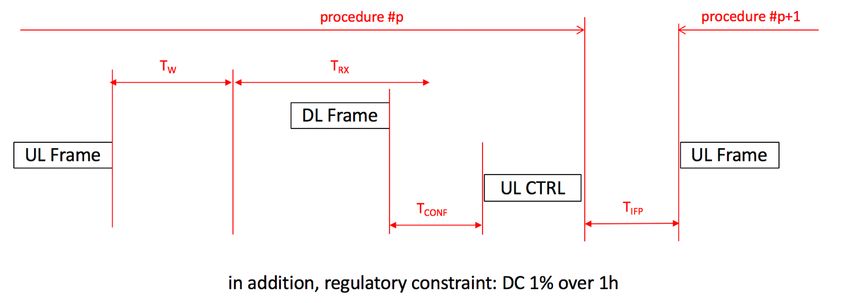
Ref.: EP-SPECS
                                             Sigfox connected objects            Rev.: 1.3
                                                Radio specifications
                                                                                 Date: Feb. 2019

1          INTRODUCTION
This document describes the radio interface between Sigfox connected objects and Sigfox network
(see Figure 1-1). This radio interface implements Sigfox V1 radio communication rules, revision 1.3,
which main functions are illustrated in Figure 1-2.

                                     Figure 1-1 : Radio interface

To ensure consistency in documents describing the Sigfox solution, Sigfox radio communication
rules are named "3D-UNB" or "3D-UNB rules" in the present document. Sigfox connected objects
are named end-points (EP). 3D stands for triple diversity, i.e. diversity in time, in frequency and in
space.

                Figure 1-2 : Main functions of Sigfox V1 radio communication rules

NOTE 1: the present document specifies radio interface for objects connected to a 3D-UNB network,
as a whole. Description and technical specifications of radio hubs (i.e. Sigfox base stations) and
Sigfox cloud are out of scope of the present document.
NOTE 2: some features, described here after, may not be available in all countries, where Sigfox
network is operated.
NOTE 3: following what is in the present document is a prerequisite, but not a guarantee, for getting
Sigfox certification.

EP-SPECS                             © copyright Sigfox - all rights reserved                Page 4 of 36
Ref.: EP-SPECS
                                              Sigfox connected objects           Rev.: 1.3
                                                 Radio specifications
                                                                                 Date: Feb. 2019

2          RADIO HARDWARE ENGINEERING
2.1 Local regulation constraints
3D-UNB is designed to operate in license-free frequency bands. In each country, these frequency
bands are ruled by local regulations, that define technical constraints for sharing the unlicensed
spectrum.

As local regulations may vary from country to country, Sigfox has defined Radio Configurations that
define radio parameter values that comply local regulations for a set of countries. Radio parameters
values corresponding to a radio configuration are called a regional profile.

End-points have to comply with local regulations and implement Sigfox' radio configuration
parameters for each country, where they are intended to be used.

NOTE: constraints on uplink and downlink traffic model, that end-points may use to comply with
commercial data plans, are out of scope of the present document.

2.1.1 ETSI 300 220: duty cycle
In European countries, access to the unlicensed spectrum is ruled by Duty Cycle (DC) limits and Tx
power limits. The applicable regulations are:

[NORM1]      Short Range Devices (SRD) operating in the frequency range 25 MHz to 1000 MHz; Part
             1: Technical characteristics and methods of measurement - ETSI EN 300 220-1 -
             Revision 3.1.1 - February 2017
[NORM2]      Short Range Devices (SRD) operating in the frequency range 25 MHz to 1000 MHz; Part
             2: Harmonized Standard for access to radio spectrum for non-specific radio equipment
             - ETSI EN 300 220-2 - Revision 3.2.0 - September 2017

2.1.2 FCC 15 247: frequency hopping
In North American countries, access to the unlicensed spectrum is ruled by dwell time limits and
Frequency Hopping (FH) constraints. The US applicable regulation is:

[NORM3]      CFR Title 47 Part 15 section 15.247 - Operation within the bands 902-928 MHz, 2400-
             2483.5 MHz, and 5725-5850MHz - April 7, 2017

2.1.3 ARIB T108: listen before talk
In Japan, access to the unlicensed spectrum is ruled by Listen Before Talk (LBT) and Tx power limits.
The Japanese applicable regulations are:

EP-SPECS                              © copyright Sigfox - all rights reserved              Page 5 of 36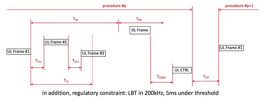
Ref.: EP-SPECS
                                               Sigfox connected objects                    Rev.: 1.3
                                                  Radio specifications
                                                                                           Date: Feb. 2019

[NORM4]       (English translation) 920MHz-Band Telemeter, Telecontrol and Data Transmission
              radio equipment - ARIB STD-T108 - version1.2 - 2nd July 2018

2.1.4 Regional profile beaconing
Sigfox implementation of 3D-UNB uses several specific broadcast messages to help mobile end-
points discovering what is the regional profile operated on their location. These broadcast messages
are encapsulated in DL frames that have specific PHY format and modulation patterns. They are
described in a dedicated Sigfox Specification document.

2.2 Frequency ranges, macro- and micro- channels
Table 2-1 and Table 2-2 define frequency ranges where an end-point may communicate. Depending
on local regulations, one or several 200kHz reference macro channels are defined within these
frequency ranges.

When local regulations require frequency hopping techniques, end-point shall use 25kHz micro-
channels. It shall implement at least 6 contiguous micro-channels within each usable frequency
segment (see 3.13.3).

                                   Table 2-1 : UL frequency ranges
 Frequency
                    RC1          RC2                 RC3                    RC4        RC5           RC6
  (in MHz)
     low
                868.030         902.100           923.100                920.700     923.200       865.100
 boundary
 center (*)     868.130         902.200           923.200                920.800     923.300       865.200
     high
                868.230         904.700           923.300                923.300     923.400       865.300
 boundary
                      (*): center frequency of first UL reference macro channel

                                   Table 2-2 : DL frequency ranges
       Frequency
                          RC1        RC2                  RC3                RC4     RC5          RC6
        (in MHz)
           low
                     869.425       905.100             922.100            922.200   922.200     866.200
       boundary
       center (*)    869.525       905.200             922.200            922.300   922.300     866.300
           high
                     869.625       907.700             922.300            924.800   922.400     866.400
       boundary
                      (*): center frequency of first DL reference macro channel

EP-SPECS                               © copyright Sigfox - all rights reserved                         Page 6 of 36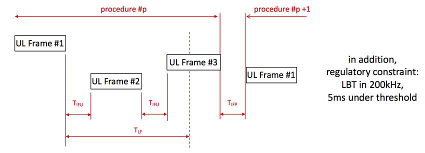
Ref.: EP-SPECS
                                                 Sigfox connected objects                     Rev.: 1.3
                                                    Radio specifications
                                                                                              Date: Feb. 2019

2.2.1 Frequency reference stability
In 3D-UNB, the end-point frequency stability has two impacts:
       - a shift of the end-point usable frequency segment,
       - a drift of carrier center frequency in radio bursts transmitted by the end-point.

Maximum shift of the end-point usable frequency segment is related to the overall accuracy of its
frequency reference used for radio frequency synthesis. This overall accuracy includes all sources of
frequency change, such as production inaccuracy, temperature drift, aging drift, supply voltage
drift, …

End-points shall have an overall accuracy of +/- 20ppm for their frequency reference.

End-points shall ensure that peak and mean drifts of carrier center frequency within an UL radio
burst comply with Table 2-3.

                              Table 2-3: Frequency drifts within a radio burst
                                                    BR100UL               BR600UL
                     Peak frequency drift        +/- 30 Hz/sec         +/- 100Hz/sec
                     Mean frequency drift        +/- 20 Hz/sec          +/- 50Hz/sec

where:
           -   the peak frequency drift is evaluated over the first 19 symbols of a radio burst (i.e.
               symbols corresponding to the UL-Pr field),
           -   the mean frequency drift is evaluated over the symbols corresponding to the FT field and
               the UL-PHY-CONTENT field.

3D-UNB network (SNW) implements UL and DL macro-channel center frequencies with an accuracy
of +/- 1,62 ppm.

2.3 Symbol rates
In uplink, end-point may select the symbol rate (see Table 2-4) on a per message basis and according
to regional profile allowance (see Table 2-5).
It shall use the same symbol rate for all the radio bursts associated to a message.

The duration of an uplink symbol is named TSUL.

                                  Table 2-4: Symbol rates in 3D-UNB system
                                        Symbol rate             Symbol rate         Symbol rate
                    Communication
                                           name                  (in baud)          accuracy (*)
                                          BR100UL                   100               +/- 0,1%
                         uplink
                                          BR600UL                   600               +/- 0,1%
                       downlink           BR600DL                   600              +/- 0,01%

EP-SPECS                                 © copyright Sigfox - all rights reserved                        Page 7 of 36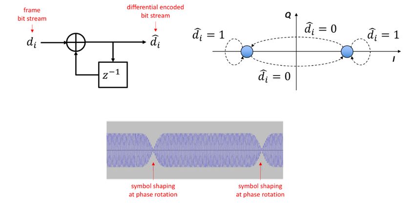
Ref.: EP-SPECS
                                                 Sigfox connected objects                          Rev.: 1.3
                                                    Radio specifications
                                                                                                   Date: Feb. 2019

                      (*): accuracy evaluated over one radio burst of maximum length

                        Table 2-5: Allowed symbol rates in uplink per regional profile
                            RC1          RC2            RC3                   RC4           RC5          RC6
       allowed            BR100UL                    BR100UL                             BR100UL      BR100UL
       symbol rates       BR600UL     BR600UL        BR600UL              BR600UL        BR600UL      BR600UL

End-point shall keep the jitter on uplink symbol duration lower or equal to +/- 1%.

For downlink radio bursts, SNW uses symbol rate BR600DL, as specified in Table 2-4.
The duration of a downlink symbol is named TSDL.

2.4 End-point Tx characteristics
2.4.1 Output power
In 3D-UNB systems, the output power of an end-point is defined by giving a target transmit power
(EP-PwrTARG). EP-PwrTARG value is expressed in dBm EIRP; it is profile dependent. This target value
(see Table 2-6) is used to evaluate coverage of 3D-UNB systems in each country.

                                Table 2-6 : Target output power of end-point
             Power
                              RC1         RC2                RC3                RC4         RC5           RC6
           (dBm EIRP)
           EP-PwrTARG          16          24                 16                    24       14           16

2.4.2 Power class
An end-point, that transmits at EP-PwrTARG, is said to be "Class 0".
When local regulation allows, end-point may transmit at higher transmit power, but the drawback
is an increased power consumption.
An end-point may transmit at lower transmit power, but the drawback is a reduced quality of service
in uplink.
Four end-point power classes are defined, as in Table 2-7.

                                     Table 2-7: End-point power classes
           Tx Power                   End-point actual transmit power (in dBm EIRP)
             Class                 max.                     typ.                  min.
               0             local regulation            EP-PwrTARG           EP-PwrTARG - 4
               1             EP-PwrTARG - 4                  EP-PwrTARG - 6                  EP-PwrTARG - 9
               2             EP-PwrTARG - 9                 EP-PwrTARG - 11                 EP-PwrTARG - 14
               3             EP-PwrTARG - 14                EP-PwrTARG - 16                   not defined

EP-SPECS                                 © copyright Sigfox - all rights reserved                               Page 8 of 36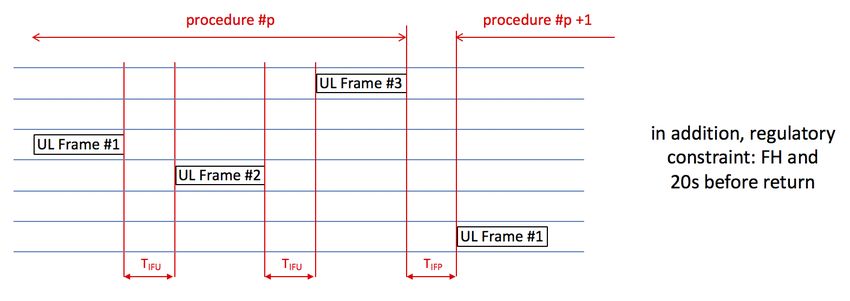
Ref.: EP-SPECS
                                              Sigfox connected objects                   Rev.: 1.3
                                                 Radio specifications
                                                                                         Date: Feb. 2019

2.4.3 Uplink modulation scheme
3D-UNB implements a differential binary phase shift keying (D-BPSK) modulation in uplink (see
Figure 2-1). A symbol shaping is added during the phase rotation, to keep the emission spectrum
within the limits defined in section 2.4.4.

                               Figure 2-1 : D-BPSK principle in 3D-UNB

The end-point shall have a phase modulation accuracy in uplink as specified in Table 2-8.

                               Table 2-8: modulation accuracy values
                              Parameter                                          Value
                   Maximum modulation RMS phase error                             10°
                   Maximum modulation peak phase error                            30°

Before the first symbol corresponding to the first bit of a frame, a radio burst may start with a ramp-
up and extra symbols (see Figure 2-2). This extra transmission shall be less or equal to 2 x TSUL and
with no phase modulation in it.

In the same manner, a radio burst may end with extra symbols and a ramp down (see Figure 2-2).
This extra transmission shall be less or equal to 2 x TSUL and with no phase modulation in it.

EP-SPECS                              © copyright Sigfox - all rights reserved                      Page 9 of 36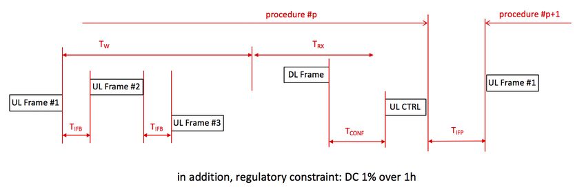
Ref.: EP-SPECS
                                              Sigfox connected objects                Rev.: 1.3
                                                 Radio specifications
                                                                                      Date: Feb. 2019

                                   Figure 2-2 : radio burst shaping

NOTE: the starting point and the ending point of a radio burst are the times where the Tx power
level crosses the stabilized transmit power level minus 20dB (see Figure 2-3).

                             Figure 2-3: Ramp-up and ramp-down limits

2.4.4 Tx spectrum mask
The Tx spectrum of a 3D-UNB end-point results from the modulation process within radio bursts
and the switching transients. Tx spectrum limits are defined in Table 2-9 and illustrated in Figure 2-4.

                                  Table 2-9: Tx spectrum mask in UL
                                                               Relative power level
                         Frequency intervals
                                                                      (in dBc)
                         [-1/TSUL ; +1/TSUL]                              0
                          [+1/TSUL ; +3/TSUL]
                                                                            -20
                           [-3/TSUL ; -1/TSUL]
                          [+3/TSUL ; +5/TSUL]
                                                                            -35
                           [-5/TSUL ; -3/TSUL]
                              over +5/TSUL
                                                                            -45
                             under -5/TSUL

EP-SPECS                              © copyright Sigfox - all rights reserved                  Page 10 of 36
Ref.: EP-SPECS
Sigfox connected objects Rev.: 1.3
Radio specifications
Date: Feb. 2019
Figure 2-4: End-point Tx spectrum mask
NOTE: end-point Tx spectrum is evaluated with a resolution bandwidth of 10Hz and averaged over
each step of 200Hz.
2.5 End-point Rx characteristics
2.5.1 Foreword on end-point Rx characteristics
3D-UNB is designed to operated even if some end-points are uplink only. Receiving capability is
optional in end-point. Therefore, values for the technical parameters listed in the present section
are target values, recommended for getting a good downlink behavior if the final usage of an end-
point requires bidirectional communications.
Engineering designers are strongly encouraged to pay close attention to end-point receivers,
because their characteristics have a direct impact on the overall performance of the downlink
communication.
2.5.2 Modulation scheme in DL
For downlink transmission, 3D-UNB implements a GFSK modulation with 600 baud symbol rate (see
Table 2-4) and a frequency deviation of ∆fMOD = 800Hz.
2.5.3 Nominal error rate
The nominal error rate applies to nominal and static conditions without interference.
For 3D-UNB end-points, the nominal frame error rate shall be FERNOM = 10-6, evaluated with a
conducted input level 10dB above RxSensREF.
2.5.4 Reference sensitivity
In 3D-UNB systems, reference receiver sensitivity (RxSensREF) is defined as the conducted input level
at which the reference error rate of FERREF=10% is met, when evaluated over 1000 frames.
RxSensREF value is -126dBm.
EP-SPECS © copyright Sigfox - all rights reserved Page 11 of 36Ref.: EP-SPECS
Sigfox connected objects Rev.: 1.3
Radio specifications
Date: Feb. 2019
2.5.5 Target end-point radiated sensitivity
In 3D-UNB systems, the sensitivity of an end-point is defined by giving a target end-point sensitivity
(EP-SensTARG) at the antenna. This recommended value is used to evaluate coverage of 3D-UNB
systems in each country.
The target end-point radiated sensitivity is EP-SensTARG = -126dBm, evaluated with a dipole antenna
and with FER=10%.
NOTE: although some final usages may accept less sensitivity than the target value, improved
sensitivity, improved resistance to interferers and good electromagnetic compatibility are key for
the performance of end-point receivers.
2.5.6 Downlink radio burst shaping
SNW transmits a downlink radio burst with shaping limits, as follows:
- duration of the start of radio burst less or equal to 0,5 x TSDL,
- duration of the end of radio burst less or equal to 0,5 x TSDL.
2.5.7 Resistance to interferers and blocking characteristics
For 3D-UNB end-points, the resistance to interference is driven by the end-point final usage and its
operating conditions. Table 2-10 gives target values for resistance to near interferers; Table 2-11 is
for blocking.
Table 2-10: Interference level
Carrier offset C/I
3.5kHz -30 dB
10kHz -50 dB
>1MHz -60 dB
Table 2-11: Blocking levels
Carrier offset Blocker level
± 10MHz -50dBm
2.5.8 Receiver dynamic input range
Dynamic range of receivers generally includes quite a number of technical conditions. Target value,
defined in the present clause, is an indication of the linear range, before saturation. Maximum
conducted power at end-point receiver is -42dBm.
EP-SPECS © copyright Sigfox - all rights reserved Page 12 of 36Ref.: EP-SPECS
Sigfox connected objects Rev.: 1.3
Radio specifications
Date: Feb. 2019
3 3D-UNB RULES IN UPLINK
3.1 Uplink frame construction overview
This section deals with formats and functions in uplink, from applicative/control level down to
physical level. An overview of the uplink communication stack and the corresponding construction
steps is illustrated in Figure 3-1.
Figure 3-1: Uplink communication stack overview
3.2 Uplink message content
The content of the uplink message may be applicative data or control data.
The format of an applicative message content is freely defined by the application.
The format of control message content is specified in section 5.
End-point shall copy the message content into UL-PAYLOAD field, as detailed in Table 3-1.
Table 3-1 : LI values and UL-AUTH size in relation with other message parameters
UL UL-PAYLOAD LI value UL-AUTH UL-
message content (MSB, LSB) size CONTAINER
content (in bytes) size (in bytes)
empty empty (*) 00 2 8
0b0 empty (*) 10 2 8
0b1 empty (*) 11 2 8
1 byte message content 00 2 9
2 bytes message content 10 4 12
3 bytes message content 01 3 12
4 bytes message content 00 2 12
5 bytes message content 11 5 16
6 bytes message content 10 4 16
7 bytes message content 01 3 16
EP-SPECS © copyright Sigfox - all rights reserved Page 13 of 36Ref.: EP-SPECS
Sigfox connected objects Rev.: 1.3
Radio specifications
Date: Feb. 2019
8 bytes message content 00 2 16
9 bytes message content 11 5 20
10 bytes message content 10 4 20
11 bytes message content 01 3 20
12 bytes message content 00 2 20
(*): In such case, the UL-PAYLOAD field is omitted in the UL-CONTAINER.
3.3 Length Indicator (LI)
It is a 2-bit field. EP shall set LI bits according to Table 3-1.
3.4 Bidirectional Frag (BF)
It is 1-bit field. EP shall set it, as follows:
- 0b0 in an UL-container carrying application message in a U-procedure,
- 0b1 in an UL-container carrying application message in a B-procedure.
3.5 Repeated Flag (REP)
It is a 1-bit field. EP shall set it to 0x0.
3.6 Message Counter (MC)
It is a 12-bit field. The end-point shall increment the message counter by 1 after each UL message
sent over the air. It shall rollover MC to zero, when the maximum value 409510 is reached.
NOTE: the message counter value is the same for all the N uplink frames induced by an UL message.
NOTE: the message counter is incremented after each new message, irrespective of the U- or B-
procedure used over the air.
NOTE: although there is no strong requirement on the initial value of MC, the recommended
practice is to use 0x000 as MC initial value in production.
3.7 Identifier (ID)
It is a 32-bit field. EP shall load its EP identifier bytes in reverse order into the ID field (see Figure
3-2).
EP-SPECS © copyright Sigfox - all rights reserved Page 14 of 36Ref.: EP-SPECS
Sigfox connected objects Rev.: 1.3
Radio specifications
Date: Feb. 2019
Figure 3-2: Example of EP identifier copied in ID field
3.8 Uplink Authentication (UL-AUTH)
It is a variable length field. EP shall set its length according to Table 3-1 and its content according to
the three steps, as follows:
Step 1:
To build UL-DATAIN, the end-point shall concatenate six fields in order: LI, BF, REP, MC, ID and UL-
PAYLOAD (see Figure 3-3). When payload encryption is active, the end-point shall add the RoC field,
as a first field of UL-DATAIN.
Figure 3-3: UL-DATAIN filed construction
Step 2:
The end-point shall use AES128 in mode CBC as authentication algorithm, as follows (see Figure 3-4),
where authentication key (Ka) is provided the 3D-UNB system owner.
EP-SPECS © copyright Sigfox - all rights reserved Page 15 of 36Ref.: EP-SPECS
Sigfox connected objects Rev.: 1.3
Radio specifications
Date: Feb. 2019
Figure 3-4: Principle of UL-AUTH field evaluation
Step 3:
The end-point shall copy 2 to 5 of the MSBytes of the AES/CBC result into the UL-AUTH field,
according to the length defined in Table 3-1.
3.9 Uplink error detection field (UL-CRC)
It is a 16-bit field. EP shall evaluate the UL-CRC field, as follows (see Figure 3-5):
- devise the UL-CONTAINER value with the polynomial generator X16 + X12 + X5 + 1,
- XOR the remainder with 0xFFFF.
Figure 3-5: UL-CRC computation
3.10 Uplink convolutional coding function
The end-point shall encode the concatenation of UL-CONTAINER + UL-CRC with one of the
convolutional codes in Table 3-2 and shall put the result in UL-PHY-CONTENT field (see Figure 3-6).
EP-SPECS © copyright Sigfox - all rights reserved Page 16 of 36Ref.: EP-SPECS
Sigfox connected objects Rev.: 1.3
Radio specifications
Date: Feb. 2019
Table 3-2: Polynomials for convolution coding of UL frames
Frame emission rank Polynomial
First R=1 (identity)
Second R=1+X+X2
Third R=1+X2
Figure 3-6: Convolutional coding in uplink
NOTE: in case of single frame (i.e. N=1), end-point shall use the first rank convolution code.
3.11 Uplink frame type (FT)
It is a 13-bit field. EP shall select its value according to Table 3-3.
Table 3-3: Frame type values in UL
Message Container Frame Type Frame Type UL frame
type Length value value emission
(in bytes) (in binary) (in hexa (*)) rank
8 0b0 0000 0110 1011 0x006B first
0b0 0110 1110 0000 0x06E0 second
0b0 0000 0011 0100 0x0034 third
9 0b0 0000 1000 1101 0x008D first
0b0 0000 1101 0010 0x00D2 second
Application 0b0 0011 0000 0010 0x0302 third
Message 12 0b0 0011 0101 1111 0x035F first
0b0 0101 1001 1000 0x0598 second
0b0 0101 1010 0011 0x05A3 third
16 0b0 0110 0001 0001 0x0611 first
0b0 0110 1011 1111 0x06BF second
0b0 0111 0010 1100 0x072C third
EP-SPECS © copyright Sigfox - all rights reserved Page 17 of 36Ref.: EP-SPECS
Sigfox connected objects Rev.: 1.3
Radio specifications
Date: Feb. 2019
20 0b0 1001 0100 1100 0x094C first
0b0 1001 0111 0001 0x0971 second
0b0 1001 1001 0111 0x0997 third
16 0b0 1111 0110 0111 0x0F67 first
Control
0b0 1111 1100 1001 0x0FC9 second
Message
0b1 0001 1011 1110 0x11BE third
(*): Hexadecimal values given with most significant bits padded with zero.
3.12 Uplink preamble (UL-Pr)
It is a 19-bit field. End-point shall set its value to 0b1010101010101010101.
3.13 Uplink procedure
The uplink only procedure (i.e. U-procedure) is initiated by an end-point wishing to send a UL
message to 3D-UNB network, with no onward downlink message. The end-point chooses the U-
procedure on a per message basis.
3.13.1 Single/multiple frame principle
For an uplink message, 3D-UNB rules allow to create one or three frame(s) and then to transmit one
or three radio burst(s) over the air. This feature is named single/multiple frame.
The parameter N defines the number of uplink frames per message (see Figure 3-7). The selection
of N=1 results in the lowest end-point energy consumption, whereas a value of N=3 provides
increased resiliency. N=2 is not permitted. End-point shall set the FT value according to Table 3-3
Figure 3-7: Principle of multiple transmissions in uplink
NOTE: single or multiple frame(s) carry the same UL-CONTAINER and the same UL-CRC ; only
convolution code and FT value are different.
3.13.2 Time intervals in U-procedure
Time intervals in U-procedures are illustrated in Figure 6-1 to Figure 6-6, with values as follows:
EP-SPECS © copyright Sigfox - all rights reserved Page 18 of 36Ref.: EP-SPECS
Sigfox connected objects Rev.: 1.3
Radio specifications
Date: Feb. 2019
Table 3-4 : Time interval values for frames in U-procedure
RC1 RC2 RC3 RC4 RC5 RC6
TIFU MIN 4 x TSUL 4 x TSUL 4 x TSUL 4 x TSUL 4 x TSUL 4 x TSUL
TIFU MAX 2000ms 2000ms N.A. 2000ms N.A. 2000ms
TIFP MIN 4 x TSUL 4 x TSUL 4 x TSUL 4 x TSUL 4 x TSUL 4 x TSUL
TIFP MAX N.A. N.A. N.A. N.A. N.A. N.A.
TLF N.A. N.A. 8s N.A. 8s N.A.
3.13.3 Frequency selection in U-procedure
An end-point picks the carrier center frequency of each radio burst randomly within its usable
frequency segment. Carrier center frequencies are statistically independent and evenly distributed
over the end-point usable frequency segment.
The usable frequency segment of an end-point is defined as the uplink macro channel, where the
3D-UNB system is operated, reduced by the upper and lower frequency amount required to
compensate the shift of the end-point reference frequency over the end-point life time.
The end-point shall select the center carrier frequency fUL of each radio burst pseudo-randomly. The
end-point shall ensure that:
- pseudo-random frequencies are statistically independent and evenly distributed over its
usable frequency segment,
- its pseudo-random frequency series is unique for each end-points,
- a gap of at least 20/TSUL Hz exists between the carrier center frequencies of two
successive radio bursts.
When local regulations define channelization constraints, the end-point shall ensure that the fUL
distribution is independent and evenly distributed among the channels as well as within each of the
channels.
When generating carrier center frequencies of uplink radio bursts, the end-point shall use a
granularity less or equal to 100Hz.
EP-SPECS © copyright Sigfox - all rights reserved Page 19 of 36Ref.: EP-SPECS
Sigfox connected objects Rev.: 1.3
Radio specifications
Date: Feb. 2019
4 3D-UNB RULES IN DOWNLINK
4.1 Downlink frame construction overview
This section deals with formats and functions in downlink, from applicative/control level down to
physical level. An overview of the downlink communication stack and the corresponding
construction steps are illustrated in Figure 4-1.
Figure 4-1: Downlink communication stack overview
4.2 Downlink message content
The content of downlink message is a fixed-length field. It carries applicative data prepared by user's
distant application server in response to an uplink message. Format of the DL-PAYLOAD field is user
dependent.
4.3 Downlink authentication (DL-AUTH)
DL-AUTH field is evaluated in three steps by 3D-UNB network:
Step 1:
SNW concatenates five fields in order (see Figure 4-2) to build DL-DATAIN.
Step 2:
SNW runs the AES128 algorithm (see Figure 4-3) on DL-DATAIN and with the authentication key (Ka),
known by the 3D-UNB system owner.
EP-SPECS © copyright Sigfox - all rights reserved Page 20 of 36Ref.: EP-SPECS
Sigfox connected objects Rev.: 1.3
Radio specifications
Date: Feb. 2019
Figure 4-2: DL-DATAIN construction principle
Step 3:
SNW copies the two MSByte of the AES128 result into the DL-AUTH field.
Figure 4-3: DL-AUTH computation
4.4 Downlink error detection (DL-CRC)
SNW evaluates the DL-CRC field (see Figure 4-4), as follows:
- devise the DL-CONTIANER value with the polynomial generator X8 + X5 + X3 + X2 + X + 1,
- copy the remainder in DL-CRC field.
EP-SPECS © copyright Sigfox - all rights reserved Page 21 of 36Ref.: EP-SPECS
Sigfox connected objects Rev.: 1.3
Radio specifications
Date: Feb. 2019
Figure 4-4: DL-CRC field evaluation in DL
4.5 Downlink error correction (ECC)
The error correction function in downlink implements BCH15-11 Error Correction Codes over the
concatenation of DL-CONTAINER and DL-CRC fields.
SNW evaluates the ECC field in two steps (see Figure 4-5).
Figure 4-5: ECC field computation in DL
4.6 Downlink whitening function
SNW evaluates the DL-PHY-CONTENT in three steps (see Figure 4-6), as follows:
- Evaluate the initialization value of the whitening function as (End-Point Identifier x MC)
mod512, where MC value is from the uplink frame of the corresponding bidirectional
sequence,
- If (End-Point Identifier x MC) mod512 equals 0, set the initialization value to 51110,
EP-SPECS © copyright Sigfox - all rights reserved Page 22 of 36Ref.: EP-SPECS
Sigfox connected objects Rev.: 1.3
Radio specifications
Date: Feb. 2019
- XOR the concatenation of ECC, DL-CONTAINER and DL-CRC fields, in order, with the
pseudo-random bit stream generated by the PN9 polynomial: R=X9+X4+1 initiated with
the above initialization value.
Figure 4-6: Whitening function in DL
4.7 Downlink frame type (FT)
It is a 13-bit long, with value 0b1001000100111 (i.e. 0x1227 when MSbits are zero padded).
4.8 Downlink preamble (DL-Pr)
It is a 91-bit field (see Figure 4-7). Its value is a string of bits composed of 1 and 0 alternately, ending
with a 1.
Figure 4-7: DL preamble content
4.9 Bidirectional procedure
The B-procedure is initiated by an end-point wishing to send an UL message and to receive an
onward downlink message.
If a downlink message is sent by the network and received successfully at MAC/LINK level in the
end-point, a confirmation message is sent by end-point. When the DL message is not received, the
confirmation message is omitted.
The end-point selects the B-procedure on a per message basis. It can mix it with single/multiple
frame procedure. Figure 4-8 illustrates the sequence diagram of a B-procedure.
EP-SPECS © copyright Sigfox - all rights reserved Page 23 of 36Ref.: EP-SPECS
Sigfox connected objects Rev.: 1.3
Radio specifications
Date: Feb. 2019
Figure 4-8: B-procedure sequence diagram at MAC/LINK level
4.9.1 Time intervals in B-procedures
Time intervals in B-procedures are illustrated in Figure 6-7 to Figure 6-12, with values as follows:
Table 4-1 : Time interval values in B-procedure at MAC/LINK level
RC1 RC2 RC3 RC4 RC5 RC6
TW 20s 20s 19s 20s 19s 20s
TRX 25s 25s 33.5s 25s 33.5s 25s
TCONF MIN 1.4s 1.4s 1.4s 1.4s 1.4s 1.4s
TCONF MAX 4s 4s 4s 4s 4s 4s
Table 4-2 : Time interval values in B-procedure at PHY level
RC1 RC2 RC3 RC4 RC5 RC6
TIFB MIN 500ms 500ms 4 x TSUL 500ms 4 x TSUL 500ms
TIFB MAX 525ms 525ms N.A. 525ms N.A. 525ms
TIFP MIN 4 x TSUL 4 x TSUL 4 x TSUL 4 x TSUL 4 x TSUL 4 x TSUL
TIFP MAX N.A. N.A. N.A. N.A. N.A. N.A.
TLF N.A. N.A. 8s N.A. 8s N.A.
NOTE: definition of TIFP prevents an end-point to interpose a new procedure when waiting for
reception window in a B-procedure.
4.9.2 Frequency selection in B-procedure
Generally speaking, EP shall select carrier center frequency of its first uplink frame in a B-procedure
the same way as in U-procedure (see section 3.13.3).
EP-SPECS © copyright Sigfox - all rights reserved Page 24 of 36Ref.: EP-SPECS
Sigfox connected objects Rev.: 1.3
Radio specifications
Date: Feb. 2019
In case of multiple frame procedure, second and third carrier center frequencies have a fixed
difference ∆fMF with the first one (see Figure 4-9).
Carrier center frequency of the radio burst sent back by SNW is shifted by ∆fGAP from the carrier
center frequency of the corresponding uplink radio burst (see Figure 4-9).
∆fMF and ∆fGAP are regional profile dependent and defined in Table 4-3.
Table 4-3 : Frequency parameters in B-procedure
RC1 RC2 RC3 RC4 RC5 RC6
∆fMF 6kHz 25kHz 6kHz 25kHz 6kHz 6kHz
∆fGAP 1.395MHz 3.0MHz -1.0MHz 1.5MHz -1.0MHz 1.1MHz
Figure 4-9 : Frequency layout in B-procedure
EP shall select carrier center frequency for the UL control message, sent at successful completion of
a B-procedure, pseudo-randomly in compliance with UL frequency selection described in section
3.13.3.
EP-SPECS © copyright Sigfox - all rights reserved Page 25 of 36Ref.: EP-SPECS
Sigfox connected objects Rev.: 1.3
Radio specifications
Date: Feb. 2019
5 APPLICATIVE/CONTROL LEVEL
5.1 Keep-alive control message
The keep-alive control message (see Figure 5-1) is optionally sent by the end-point for reporting
local parameters. End-point shall send a keep alive control message in a multiple frame procedure
(i.e. three frames) and with the following four fields in order:
- Control Type (CT) field is 8-bit long. Its value shall be 0x08,
- VDD-IDLE field is a 16-bit unsigned integer. It shall contain the battery voltage value
outside an EP radio burst transmission with 1mV per unit (i.e. voltage from 0mV to
65 535mV),
- VDD-Tx field is a 16-bit unsigned integer. It shall contain the battery voltage value within
an EP radio burst transmission with 1mV per unit (i.e. voltage from 0mV to 65 535mV),
- TEMP field is a 16-bit signed integer. It shall contain the EP temperature with 0,1°C per
unit.
Figure 5-1 : Payload of a keep-alive control message
5.2 Confirmation control message
The UL confirmation control message (see Figure 5-2) is mandatorily sent by the end-point after the
successful reception of a downlink message in a B-procedure. End-point shall send an UL
confirmation control message in a single frame procedure (i.e. one frame) and with the following
five fields in order:
- Control Type (CT) field is 8-bit long. Its value shall be 0x09,
- VDD-IDLE field is a 16-bit unsigned integer. It shall contain the battery voltage value
outside an EP radio burst transmission with 1mV per unit (i.e. voltage from 0mV to
65 535mV),
- VDD-Tx field is a 16-bit unsigned integer. It shall contain the battery voltage value within
an EP radio burst transmission with 1mV per unit (i.e. voltage from 0mV to 65 535mV),
- TEMP field is a 16-bit signed integer. It shall contain the EP temperature with 0,1°C per
unit,
- RSSI field is an 8-bit signed integer. It shall code the received signal strength (RSS)
estimation, made by the end-point over the DL frame of the B-procedure, with the
following formula: RSSI = “EP RSS estimation” +100 (unit: dBm)
EP-SPECS © copyright Sigfox - all rights reserved Page 26 of 36Ref.: EP-SPECS
Sigfox connected objects Rev.: 1.3
Radio specifications
Date: Feb. 2019
Figure 5-2 : Payload of a UL confirmation control message
5.3 Applicative payload encryption
Payload encryption is a procedure that encrypts the payload of applicative messages over the air, in
both uplink and downlink communication. It uses an AES128 algorithm in mode CTR with an
encryption key (Ke), unique per end-point. The procedure is specified in a dedicated Sigfox
specification document.
EP-SPECS © copyright Sigfox - all rights reserved Page 27 of 36Ref.: EP-SPECS
Sigfox connected objects Rev.: 1.3
Radio specifications
Date: Feb. 2019
6 ANNEX A (INFORMATIVE): TIME INTERVAL RECAP
This informative annex recaps how time intervals apply depending on U- or B- procedures, single or
multiple frames and spectrum sharing techniques (i.e. DC, FH or LBT). Twelve configurations are
possible. For each configuration, the relevant time intervals are illustrated here after.
NOTE: relative frame positions on frequency vertical axis are purely indicative.
Figure 6-1 : U-procedure, single frame, DC
Figure 6-2 : U-procedure, single frame, FH
Figure 6-3 : U-procedure, single frame, LBT
EP-SPECS © copyright Sigfox - all rights reserved Page 28 of 36Ref.: EP-SPECS
Sigfox connected objects Rev.: 1.3
Radio specifications
Date: Feb. 2019
Figure 6-4 : U-procedure, multiple frames, DC
Figure 6-5 : U-procedure, multiple frames, FH
Figure 6-6 : U-procedure, multiple frames, LBT
EP-SPECS © copyright Sigfox - all rights reserved Page 29 of 36Ref.: EP-SPECS
Sigfox connected objects Rev.: 1.3
Radio specifications
Date: Feb. 2019
Figure 6-7 : B-procedure, single frame, DC
Figure 6-8 : B-procedure, single frame, FH
Figure 6-9 : B-procedure, single frame, LBT
EP-SPECS © copyright Sigfox - all rights reserved Page 30 of 36Ref.: EP-SPECS
Sigfox connected objects Rev.: 1.3
Radio specifications
Date: Feb. 2019
Figure 6-10 : B-procedure, multiple frames, DC
Figure 6-11 : B-procedure, multiple frames, FH
EP-SPECS © copyright Sigfox - all rights reserved Page 31 of 36Ref.: EP-SPECS
Sigfox connected objects Rev.: 1.3
Radio specifications
Date: Feb. 2019
Figure 6-12 : B-procedure, multiple frames, LBT
EP-SPECS © copyright Sigfox - all rights reserved Page 32 of 36Ref.: EP-SPECS
Sigfox connected objects Rev.: 1.3
Radio specifications
Date: Feb. 2019
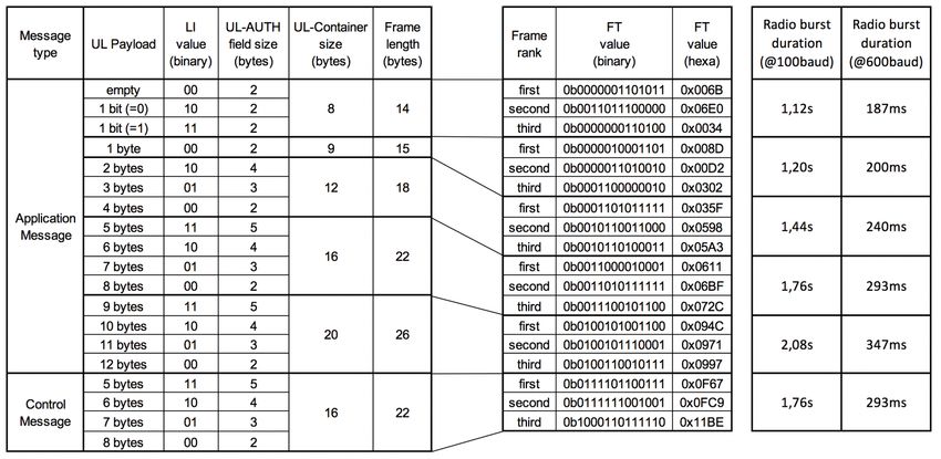
7 ANNEX B (INFORMATIVE): MESSAGE TYPES, MESSAGE
SIZES AND FRAME TYPE VALUES
EP-SPECS © copyright Sigfox - all rights reserved Page 33 of 36Ref.: EP-SPECS
Sigfox connected objects Rev.: 1.3
Radio specifications
Date: Feb. 2019
8 ANNEX C (INFORMATIVE) : DEFINITIONS, ACRONYMS
AND CONVENTIONS
8.1 Definitions
B-procedure bidirectional procedure at MAC/LINK level, triggered by an uplink
message
container datagram exchanged at MAC/LINK level in 3D-UNB
downlink communication from 3D-UNB network to an end-point
end-point leaf node of a 3D-UNB system
frame binary stream ready for modulation and transmission over the 3D-UNB
radio interface
macro-channel frequency interval within an unlicensed spectrum where end-point
may communicate
payload array of bits carried by 3D-UNB communication stack over a 3D-UNB
radio interface
radio burst radio transmission over the air which starts with a ramp up, finishes
with a ramp down and which contains a stream of symbols carrying the
modulated bits of a frame
symbol steady state in amplitude, phase and frequency of a radio wave,
carrying a piece of digital information
uplink communication from an end-point to 3D-UNB network
U-procedure uplink-only procedure at MAC/LINK level
8.2 Acronyms
3D-UNB Triple Diversity UNB
AES Advanced Encryption Standard
AUTH Authentication
BER Bit Error Rate
BF Bi-directional Flag
CRC Cyclic Redundancy Check
CT Control Type
CTR CounTeR (AES mode)
DC Duty Cycle
DL Downlink
ECC Error Correction Code
EP End-Point
EIRP Equivalent Isotropic Radiated Power
ERP Effective Radiated Power
EP-SPECS © copyright Sigfox - all rights reserved Page 34 of 36Ref.: EP-SPECS
Sigfox connected objects Rev.: 1.3
Radio specifications
Date: Feb. 2019
FER Frame Error Rate
FH Frequency Hopping
FT Frame Type
GFSK Gaussian Frequency Shift Keying
ID Identity
Ka Authentication Key (used in authentication and integrity check procedures)
Ke Encryption Key (used in payload encryption of applicative message)
LBT Listen Before Talk
LI Length Indicator
LSByte Least Significant Byte
LSbit Least Significant bit
MAC Medium Access Control
MC Message Count
MSbit Most Significant bit
MSByte Most Significant Byte
N.A. Not Applicable
PHY Physical
Pr Preamble
RC Radio Configuration
RoC Rollover Counter
RSSI Received Signal Strength Indicator
TEMP Temperature
UL Uplink
UNB Ultra-Narrow Band
VDD Positive Supply Voltage
XOR eXclusive OR (logical operation "exclusive disjunction")
8.3 Symbols
∆f fixed frequency shift for successive radio bursts sent in a B-procedure
∆fGAP frequency offset between uplink macro-channel and downlink macro-channel
fDL carrier center frequency of a DL radio burst
fUL carrier center frequency of a UL radio burst
m generic value for message numbering
N generic value for the number of UL frames transmitted at the beginning of a
unidirectional or bidirectional procedure
p generic value for MAC/LINK procedure numbering
TCONF delay between DL and confirmation message in a bidirectional procedure
TIFB time interval between uplink frames in a B-procedure
TIFP time interval between last UL frame of a procedure and the first UL frame of the
next procedure
TIFU time interval between uplink frames in a U-procedure
TLF time interval in case of multiple frame procedure when LBT applies
TSUL duration of an uplink symbol
TSDL duration of a downlink symbol
EP-SPECS © copyright Sigfox - all rights reserved Page 35 of 36Ref.: EP-SPECS
Sigfox connected objects Rev.: 1.3
Radio specifications
Date: Feb. 2019
TRX maximum duration of the receive window in a bidirectional procedure
TW waiting time between UL and DL in a bidirectional procedure
8.4 Drawing and description conventions
In this document, sketches use drawing conventions of communication protocol (see Figure 8-1),
where:
- Fields to be transmitted are drawn from left to right,
- First field on the left is transmitted first,
- Last field on the right is transmitted last,
- Fields are always transmitted MSbit first.
Figure 8-1 : Frame serialization over the air
------------------ end of document ------------------
EP-SPECS © copyright Sigfox - all rights reserved Page 36 of 36+33 (0)5 82 08 07 10 Bâtiment E-volution 425, rue Jean Rostand 31670 Labège – France Sigfox.com
You can also read