Owner's Manual Supplement - WARNING - Cannondale Bicycles
←
→
Page content transcription
If your browser does not render page correctly, please read the page content below
Owner’s Manual Supplement

      WARNING
READ THIS SUPPLEMENT AND YOUR
CANNONDALE BICYCLE OWNER’S MANUAL.
Both contain important safety information. Keep
both for future reference.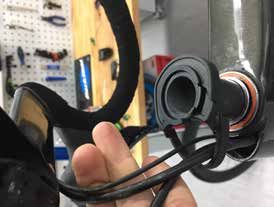
SuperSix EVO - Owner’s Manual Supplement

                                          Safety Messages
                             In this supplement, particularly important information
                                        is presented in the following ways:

                                        WARNING
                                  Indicates a hazardous situation which, if
                                  not avoided, may result in death or serious
                                  injury.

                                  NOTICE
                                  Indicates special precautions that must be
                                  taken to avoid damage.

 The following symbols are used in this manual:

     Symbol         Name                                  Description
       NG
           LI
              -2    NGLI-2 synthetic grease               Apply NGLI-2 synthetic grease.

      CR
        B-
             GE
                L   Carbon gel                            Apply carbon gel (friction paste) KF115/

                    Medium-strength
       2                                                  Apply Loctite® 242 (blue) or equivalent.
   CANNONDALE   removable
                   USA     thread lock
                                CANNONDALE      EUROPE                          CANNONDALE UK
   Cycling Sports Group, Inc.   Cycling Sports Group Europe, B.V.               Cycling Sports Group
   1 Cannondale Way,            Hanzepoort 27, 7570 GC, Oldenzaal,              Vantage Way, The Fulcrum,
   Wilton CT, 06897, USA        Netherlands +41 61 4879380                      Poole, Dorset, BH12 4NU
   1-800-726-BIKE (2453)        servicedeskeurope@                              +44 (0)1202732288
                                cyclingsportsgroup.com
   www.cannondale.com                                                           sales@cyclingsportsgroup.
                                                                                co.uk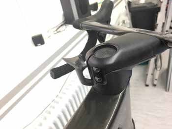
English

 Cannondale Supplements                                CONTENTS
 This manual is a “supplement” to your
 Cannondale Bicycle Owner’s Manual.                    Safety Information.....................2-5
 This supplement provides additional and               Technical Information..............6-19
 important model specific safety, maintenance,
 and technical information. It may be one of           Replacement Parts...................... 20
 several important manuals/supplements for
 your bike; obtain and read all of them.
 Please contact your Authorized Cannondale
 Dealer immediately if you need a manual
 or supplement, or have a question about
 your bike. You may also contact us using
 the appropriate country/region/location               Your Cannondale Dealer
 information.
                                                       To make sure your bike is serviced and
 You can download Adobe Acrobat PDF                    maintained correctly, and that you protect
 versions of any manual/supplement from our            applicable warranties, please coordinate
 website: http://www.cannondale.com.                   all service and maintenance through your
                                                       Authorized Cannondale Dealer.

 Contacting Cannondale                                  NOTICE
 Cannondale USA                                         Unauthorized service, maintenance, or
                                                        repair parts can result in serious damage
 Cycling Sports Group, Inc.                             and void your warranty.
 1 Cannondale Way, Wilton CT, 06897, USA
 1-800-726-BIKE (2453)

 Cycling Sports Group Europe B.V
 Mail: Postbus 5100
 Visits: Hanzepoort 27
 7575 DB, Oldenzaal, Netherlands

 International Distributors
 Consult our websIte to identify the appropriate
 Cannondale Dealer for your region.

137369                                             1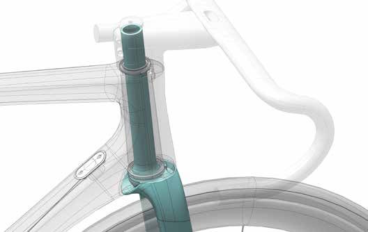
SuperSix EVO - Owner’s Manual Supplement

                               SAFETY INFORMATION

  Important Composites                                Inspection & Crash Damage
  Message                                             Of Carbon Frames/Forks

    Your bike (frame and components) is made          After A Crash Or Impact:
    from composite materials also known as
    “carbon fiber.”                                   Inspect frame carefully for damage. See
                                                      PART II, Section D. Inspect For Safety in
    All riders must understand a fundamental          your Cannondale Bicycle Owner’s Manual.
    reality of composites. Composite materials
    constructed of carbon fibers are strong           Do not ride your bike if you see any sign
    and light, but when crashed or overloaded,        of damage, such as broken, splintered, or
    carbon fibers do not bend, they break.            delaminated carbon fiber.

    For your safety, as you own and use the           Any of the following may indicate a
    bike, you must follow proper service,             delamination or damage:
    maintenance, and inspection of all the            •    An unusual or strange feel to the
    composites (frame, stem, fork, handlebar,              frame
    seat post, etc.) Ask your Cannondale
    Dealer for help.                                  •    Carbon which has a soft feel or
                                                           altered shape
    We urge you to read PART II, Section D.
    “Inspect For Safety” in your Cannondale           •    Creaking or other unexplained noises,
    Bicycle Owner’s Manual BEFORE you ride.
                                                      •    Visible cracks, a white or milky color
    You can be severely injured, paralyzed                 present in carbon fiber section
    or killed in an accident if you ignore this
                                                      Continuing to ride a damaged frame
    warning.
                                                      increases the chances of frame failure,
                                                      with the possibility of injury or death of
                                                      the rider.

137369                                            2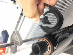
English

 Intended Use                                         Disc Brakes on Road Bikes
                     The intended use of all
                     models is                               WARNING
                     ASTM CONDITION 1,
                     High-Performance Road.            Relative to conventional rim brakes, disc
                                                       brakes are less affected by water, do not
                                                       wear or heat the rims and therefore are
                                                       more consistent. Disc brakes also may be
                                                       more powerful.
         WARNING                                       To minimize risk of injury or accidents:

   Please read your Cannondale Bicycle                 •    Understand that road bikes have a
   Owner’s Manual for more information about                relatively small tire contact patch (part
   Intended Use and Conditions 1-5.                         of the tire that touches the road). In
                                                            order to apply the brakes safely and
                                                            effectively, you may need more or less
 Servicing                                                  braking force in different situations.
                                                            You need to take into account various
                                                            road and weather conditions that can
                                                            affect traction.

   This supplement may include procedures              •    Disc brakes are excellent, but not
   beyond the scope of general mechanical                   some kind of magic. Take some time
   aptitude.                                                riding your new disc brake road bike in
                                                            lower risk circumstances to get used
   Special tools, skills, and knowledge may                 to the feel and performance of the
   be required. Improper mechanical work                    disc brakes and tires.
   increases the risk of an accident. Any
   bicycle accident has risk of serious injury,        You can be severely injured, paralyzed
   paralysis or death.                                 or killed in an accident if you ignore this
                                                       message.
   To minimize risk we strongly recommend
   that owners always have mechanical
   work done by an Authorized Cannondale
   Dealer.

137369                                            3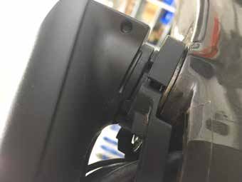
SuperSix EVO - Owner’s Manual Supplement

 Trainers                                                 Water Bottles
 If you ride a trainer that requires removal of the       Side impacts to a water bottle or cage can
 front wheel and clamps the fork dropouts: Be             result in damage to threaded inserts due to
 sure your fork quick release is tight! Relative          the leverage on a very small area. In a crash,
 movement will wear parts, weaken and                     certainly the last thing you should be worried
 damage your bike.                                        about is saving the threaded inserts in your
                                                          frame. However, when you are storing or
 If you ride a trainer that holds the bike up by
                                                          transporting your bike, take steps to prevent
 clamping the rear quick release between two
                                                          situations where a water bottle may be hit or
 cones: Take off the lightweight quick release
                                                          bumped by a strong force that would cause
 that came with your bike. Substitute a heavy,
                                                          damage. Remove bottle and cage when you
 classic all steel quick release and clamp it
                                                          are packing your bike for travel.
 tight! Relative movement will wear parts,
 weaken and damage your bike. Note that                   Periodically check the attachment of the bottle
 many modern quick releases will not fit the              cage; tighten the cage bolts if necessary.
 clamping cones in this kind of trainer because           Don’t ride with a loose bottle cage. Riding with
 their shapes are incompatible.                           loose cage bolts can produce a rocking motion
                                                          or vibration of the attached cage. A loose cage
 For thru axles, make sure you follow the trainer
                                                          will damage the insert and possibly lead to the
 manufacturer instructions for the use of any
                                                          inserts to pull out.
 required adapters.
                                                          It may be possible to repair a loose insert,
 Be particularly cautious with a carbon frame             or install another insert only if the frame is
 or fork. Carbon is relatively soft, not abrasion         undamaged. Replacement requires the use
 resistant. If there is any relative movement,            of a special tool. If you notice damage to the
 carbon will wear quickly.                                threaded insert, please ask your Cannondale
                                                          Dealer for help.
 If you ride a trainer a lot, consider using an
 old bike: Corrosion from sweat will take its
 toll. Weight is irrelevant. Save wear on your
 expensive components.
 Ask you dealer for help with trainers, the right
 one and the correct way to use it.

   NOTICE
   TRAINERS - Improperly mounting a
   bike in a trainer, or using one that is not
   compatible with your particular bike frame
   can cause serious damage.
   WATER BOTTLES - An impact, crash, or
   loose bottle cage can result in damage to
   your frame.
   These kinds of damage is not covered by
   the Cannondale Limited Warranty.

137369                                                4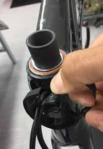
English

 Building Up A Frame Set                                 Tightening Torques
 Before building up a frame set, consult with            Correct tightening torque for the fasteners
 your Cannondale Dealer and the component                (bolts, screws, nuts) on your bicycle is very
 manufacturers, and discuss your riding style,           important to your safety. Correct tightening
 ability, weight, and interest in and patience for       torque for the fasteners is also important for
 maintenance.                                            the durability and performance of your bicycle.
                                                         We urge you to have your dealer correctly
 Make sure the components chosen are
                                                         torque all fasteners using a torque wrench. If
 compatible with your bike and intended for
                                                         you decide to torque fasteners yourself always
 your weight and riding style.
                                                         use a torque wrench.
 Generally speaking, lighter weight
                                                         Find Tightening Torque Information :
 components have shorter lives. In selecting
 lightweight components, you are making a
 trade-off, favoring the higher performance               The wide range of bicycle models and
 that comes with less weight over longevity.              components used means that a listing of
 If you choose more lightweight components,               tightening torque would be out of date by
 you must inspect them more frequently. If you            the time it was published. Many fasteners
 are a heavier rider or have a rough, abusive             should be installed with a thread locking
 or “go for it” riding style, buy heavy duty              adhesive such as Loctite®.
 components.
                                                          To determine correct tightening torque
 Read and follow the component                            and any adhesive application for a
 manufacturers warnings and instructions.                 fastener we ask you to check:
                                                          •    Many components are marked.
                                                               On-product marking is becoming
                                                               common.
                                                          •    Torque specs in the component
                                                               manufacturers instructions shipped
                                                               with your bicycle.
                                                          •    Torque specs listed on the websites of
                                                               component manufacturers.
                                                          •    With your dealer. Dealers have access
                                                               to current data and have experience
                                                               with correct torque for most
                                                               fasteners.

137369                                               5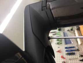
SuperSix EVO - Owner’s Manual Supplement

                            TECHNICAL INFORMATION

  Frame Specifications

  SuperSix Evo HM/Carbon Disc
   Item                                          Specification
   Head Tube                                     Sizes 44-54 cm: UPR: 1-1/8 in, LWR: 1-1/4 in
                                                 Sizes 56-62 cm: UPR: 1-1/8 in, LWR: 1-3/8 in
   Headset                                       Sizes 44-54 cm: Integrated, 1-1/8 in - 1-1/4 in
                                                 Sizes 56-62 cm: Integrated, 1-1/8 in - 1-3/8 in
   Bottom Bracket: Type/Width                    PF30A / 73 mm
   Front Derailleur                              Brazed-on
   Seat Post: Dia./Binder                        HG/HGSL 27 KNOT / Internal Wedge
         Min. Seat Post Insert                   65 mm

         Max. Seat Post Insert                   44cm-140 mm, 48 cm - 179 mm,
                                                 51-62 cm (measure)
         Tire Size x Max. Width                  700c x 30 mm (measured)
   Fork Maximum Turning Angle                    +/- 55°
   Brakes: Mount Type / Min/Max Rotor Dia.       RR: Flat Mount / 140 mm / 160 mm
                                                 FT: Flat Mount / 140 mm / 160 mm
   Axles: Type / Hub Spacing / Length            RR: Speed Release TA Double Lead / 142 x 12
                                                 mm / 165 mm
                                                 FT: Speed Release TA Double Lead / 100 x 12
                                                 mm / 119 mm”
         Intended Use:                           ASTM Condition 1

       Max. Weight Limit: Total                  285 lbs / 129 kg
    (rider+all equipment)

137369                                       6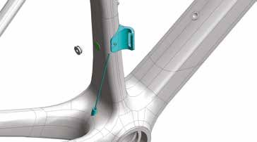
English

 SuperSix Evo Carbon Rim

  Item                                               Specification
  Head Tube                                          Sizes 44-54 cm: UPR: 1-1/8 in, LWR: 1-1/4 in
                                                     Sizes 56-62 cm: UPR: 1-1/8 in, LWR: 1-3/8 in
  Headset                                            Sizes 44-54 cm: Integrated, 1-1/8 in - 1-1/4 in
                                                     Sizes 56-62 cm: Integrated, 1-1/8 in - 1-3/8 in
  Bottom Bracket: Type/Width                         PF30A / 73 mm
  Front Derailleur                                   Brazed-on
  Seat Post: Dia./Binder                             HG/HGSL 27 KNOT / Internal Wedge
         Min. Seat Post Insert                       65 mm

         Max. Seat Post Insert                       44cm-140 mm, 48cm - 179 mm,
                                                     51-62cm (measure)
     Tire Size x Max. Width                          700c x 28 mm (measured)
  Fork Maximum Turning Angle                         +/- 55°
  Brakes: Mount Type / Min/Max Rotor Dia.            Direct Mount Rim Brakes
  Axles: Type / Hub Spacing / Length                 RR: QR / 130 x 10 mm
                                                     FT: QR / 100 x 9 mm
         Intended Use:                               ASTM Condition 1

      Max. Weight Limit: Total                       285 lbs / 129 kg
   (rider+all equipment)

 Serial Number                                                                                 1

 The serial number is located on the bottom
 bracket. It is a 7-character barcode (1).
 Use this serial number to register your bike.

         To register your bike: go to the
         Product Registration section of our
         website at www.cannondale.com

137369                                           7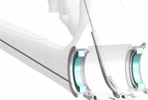
SuperSix EVO - Owner’s Manual Supplement

 Geometry
                                                                                             B
  A          Seat Tube Length
  B          Top Tube Horizontal                                                                      P
                                                                    A
  D          Head Tube Angle                                                                                               G
  E          Seat Tube Angle
                                                                                         75 mm
  G          Head Tube Length                                                                    F
  H          Wheelbase                                                                                                              O

  I          Front Center
                                                                                                                   D
  J          Chain Stay Length                                              E
  K          Bottom Bracket Drop
                                                       K
  L          Bottom Bracket Height
                                                                        J                                      I                        M
  M          Fork Rake
                                                                                            L
  N          Trail
  O          Stack
                                                                                                                                          N
  P          Reach                                                                           H

                                                                                                 Dimensions = centimeter/inches

      Size               44           48          51          54                  56                      58              60                62
         A           40.0/15.7     43.8/17.2   47.7/18.8   51.5/20.3        53.6/21.1            55.8/22.0             57.9/22.8        60.0/23.6

         B           51.2/20.2     52.0/20.5   52.8/20.8   54.6/21.5        56.2/22.1            57.8/22.8             59.4/23.4        61.1/24.1
         D            70.9°          71.2°         *            *                73.0°                    *                *                  *
         E             74.3°           *           *         73.7°               73.3°                72.9°              72.5°            72.1°
         G            9.9/3.9       11.4/4.5    13.0/5.1   15.3/6.0             16.4/6.5             18.8/7.4          20.9/8.2         23.0/9.1
         H           97.9/38.5     98.5/38.8   99.4/39.1   100.8/39.7       99.2/39.1            100.5/39.6            101.6/40.0   102.8/40.5

         I           58.2/22.9     58.8/23.2   59.7/23.5   61.1/24.0        59.5/23.4            60.7/23.9             61.8/24.3        63.0/24.8

         J           40.8/16.1         *           *            *                  *                      *                *                  *
         K            7.4/2.9          *           *        7.2/2.8                *                 6.9/2.7               *                  *
         L           26.8/10.6         *           *       27.1/10.6               *              27.3/10.7                *                  *
         M            5.5/2.2          *           *            *               4.5/1.8                   *                *                  *
         N            6.0/2.4       5.8/2.3        *            *               5.8/2.3                   *                *                  *
         O           50.4/19.8     51.9/20.4   53.4/21.0   55.4/21.8        57.4/22.6            59.4/23.4             61.4/24.2        63.4/25.0

         P           37.0/14.6     37.4/14.7   37.8/14.9   38.4/15.1        39.0/15.3            39.5/15.6             40.0/15.8    40.6/16.0

* Indicates same.

All Specifications subject to change without notice.

137369                                                      8
English
Bottom Bracket - PF30A / 73 mm
Cross-section Side view, Drive side, no bearings
1
2
46 mm
3
34 mm 39 mm
DRIVE SIDE NON-DRIVE SIDE Identification
1. Frame BB Shell
73 mm 2. PF30 Cup
3. Bearing
Maintenance
Follow the manufacturer’s instruction for assembly
Have the bearings inspected annually, anytime the and installation of the bearing system. Use a headset
crankset is removed, or if a problem is indicated. press such as Park Tool HHP-2. See www.parktool.
With crankset removed, rotate the inner bearing com/product/bearing-cup-press-HHP-2
race of both bearings; rotation should be smooth Select appropriate press and adapters to ensure that
and quiet. Execessive play, roughness, or corrosion
force is only applied to the cup and not the bearing
indicates a damaged bearing.
inside. Press until both cup flanges are mated to the
BB shell edge.
Replacement
Bearings are not removable from the PF30 cup NOTICE
systems pressed into the bottom bracket shell. • Consult with your Cannondale Dealer on the
Therefore, both bearing and cup must be removed quality and compatibilty of any proposed
together replaced as a new set. replacement component.
Before installing any new bearing units into the shell, • Do not use chemical solvents to clean. Do
thoroughly clean the inside surface of the bottom not remove frame material or use surfacing
bracket shell with a clean dry shop towel. Also, make tools on bottom bracket shell.
sure both bearing units and the BB shell surfaces are
• Frame damage, caused by improper
clean and dry. Do not apply
components, component installation or
grease.
removal is not covered by your warranty.
To avoid serious damage to the frame, it is important
to remove bearing systems very carefully using
proper tools indicated by the manufacturer’s service
instructions. Make sure the bearings (cup or adapter
parts) are driven out squarely and evenly from inside
the shell! Do not pry components from shell.
137369 9SuperSix EVO - Owner’s Manual Supplement
DT Port Guides / Routing
Mechanical 1
1 N·m
M3
2
SHIMANO Di2
Shimano P/N
2 EW-RS910
SRAM eTAP
2 3
Identification
1. Screws
2. Cover
3. Bracket (Di2 only)
BB Cable Guides / Routing
1
a
b
a
2
1 N·m
2 M3
Identification The interior of the BB Shell is to remain free of any cable, housing
1. FD cable & rear disc brake guide. or wires passing through it. These items must be captured by the
2. RD cable & di2 cable cable guides as they emerge from the downtube and exit to the
3. Screws chainstays and seat tube.
a. Slot for Di2 cable(s).
b. Rear brake housing trough Please Note: Note Di2 cables must not touch the spindle. Use
a BB bearing assembly with a sleeve between the bearings to
protect the spindle from wear due to cables touching it.
137369 10English
Rear Derailleur Mount Front Derailleur Mount
4 3 1
2
LI-
NG
2
2
2
2 N·m
1
DISC frame shown Mechanical shift shown
1. RD Mount 1. FD Mount
2. Screw 2. FD cable
3. Frame Plug
4. Di2 Cable Plug
To replace:
Remove the rear axle.
Remove the mounting screw(s) and remove the old The front derailleur mount is bonded to the frame. It
hanger from the dropout. Clean the area around is a “braze-on type.”
the dropout and inspect the frame carefully for any
cracks or damage. If you find damage have the frame Do not attempt to remove the mount.
inspected by your Cannondale Dealer .
When using a mechanical FD system or SRAM Etap,
If the dropout is un-damaged, apply a light film of make sure the frame plug is installed to prevent the
grease between the frame and mount. This will help intrusion of water or debris into the frame.
minimize any noise or “creaking” that might result
When using Di2 Systems, use the Di2 Cable Plug.
from very slight movement between the dropout and
mount during movement of the derailleur.
Slide the new hanger onto the dropout. Apply
Loctite® 242 (or medium strength thread lock)
to the screw threads and tighten to the specified
torque.
137369 11SuperSix EVO - Owner’s Manual Supplement
Headtube Steering Angle
3
Underside of headtube.
0°
2
55° 55°
1
+/- 55 degrees
Identification NOTICE
1. Fork Stop Pin (molded)
2. Head Tube Stop Limits (molded) Do not force the steering past the stop points.
3. Steering Angle If the front end steering of the bikes is over-
loaded (due to e.g. a handlebar strike, a crash,
etc.) damage to the frame, fork or pin may result.
This type of damage is not covered by the limited
warranty.
137369 12English
Rear Brake Bridge Assy - RIM
1 2
3
4
Rear Brake Bridge Identification
1. Seat Stays
The rear brake bridge assembly parts are required 2. Brake Bridge
to be used. 3. Washer (2X)
4. Nuts (2X)
These parts provide necessary support to the frame
and ensure that braking force is not absorbed by
movement of the frame.
The parts are to be installed on the underside of the WARNING
seatstays at the frame bosses as shown.
Do not ride without a rear brake system
Do not adapt or modify the frame or the bridge parts installed.
in any way.
Do not omit or remove the rear brake bridge
Follow the instruction provided by the brake parts.
manufacturer when installing brake.
137369 13SuperSix EVO - Owner’s Manual Supplement
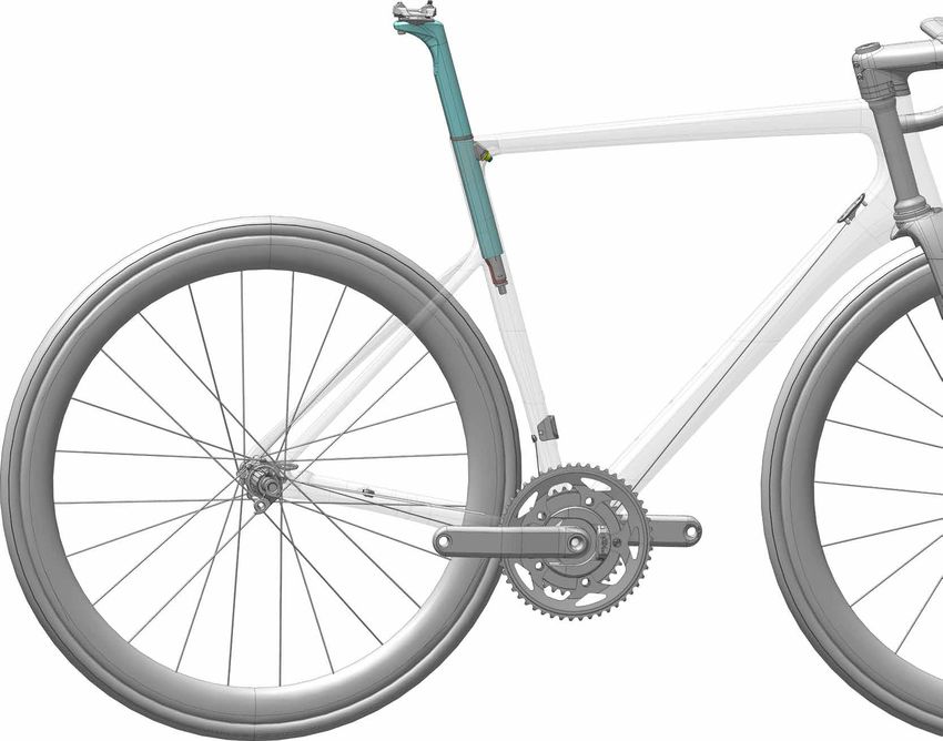
Seat Post
Installation & Adjustment Minimum Insert
Before installing: The minimum insert depth the seat post must be
inserted into the frame is 65mm.
• Use a clean shop towel to wipe out any residual
carbon gel paste from the inside the seat tube.
Maximum Insert
• Apply fresh carbon friction gel to the seat post The total length of seat post that may be inserted
and place a little bit inside the seat tube. will vary with the frame size and should be checked
in each frame.
• Make sure the seal is in good condition and in
place on the seat post. To check, carefully slide a seat post into the frame
until it stops; then lift it up 5mm.
To adjust:
1. Insert the prepared seat post into the frame. NOTICE
Maintain the specified minimum insert.
A seat post should not be bottomed out inside
2. Set the saddle height. the frame at any time. Have your Cannondale
Dealer size the seat post appropriately.
3. Insert 4 mm hex through the underside seat
tube opening as shown.
4. Tighten the binder screw to the specified torque.
WARNING
5. Slide the seal against the frame.
THE SEAT POST MUST ONLY BE CUT BY A
6. If the saddle angle adjustment is required,
loosen the saddle clamp bolts, adjust the saddle, PROFESSIONAL BIKE MECHANIC. Incorrectly
and tighten to the specified torque. cutting the seat post can result in damage
leading to an accident.
NOTICE
For more information about carbon fiber seat posts,
• Do not use any spray cleaners or solvents see also “Care and Maintenance of Carbon Fiber
to clean. Use only a clen dry shop towel. Seat Posts” in your Cannondale Bicycle Owner’s
• Do not exceed the specified torque. If Manual.
you over-tighten the binder bolt, you will
damage the binder, seat post or the frame.
Maintenance
Periodically, remove the seat post and the clamp
assembly to clean, inspect for damage and renew
the application of grease and carbon gel.
See also, “Seat Binder Inspection.”
137369 14English
1
Identification
NG
LI-
3 2
1. Saddle Clamp
2. Seat Post
3. Sliding Clamp
4. Seal CRB-GEL
5. Di2 Battery
6. Battery Bracket
7. Di2 Cable
6 N·m
Apply carbon paste 2
to entire length of the
inserted seat post
3
4
CRB-
GEL
65mm
6 N·m
CRB-GEL
Minimum Insert
CRB-GEL
5
6
Maximum Insert
5mm
Maximum Depth
7
137369 15SuperSix EVO - Owner’s Manual Supplement
Seat Binder Inspection
The internal seat binder system consists of a sliding clamp assembly and a nut base with a double-side adhesive
holding it to a special mating surface inside the seat tube. The sliding clamp parts can be removed when the seat
post is out.
Always clean the surfaces of the sliding clamp by wiping them with a clean dry lint-free shop towel only. Do
not soak the parts, as the internal washer is lubricated with grease. Solvents will wash out the lubricant and the
assembly will have to be regreased by disassembling it completely.
NOTICE
If the nut base has become rotated, it should be removed and re-affixed to the frame. The process is
described in the Service Instruction for the parts kit. These instruction are not provided in this manual. We
reccommend that you have a Cannondale Dealer perform the replacement.
Please Note: During first assembly of the nut base, it is important to not push on the 4mm allen when tightening
onto the seatpost. This can disengage the adhesive tape before proper bonding. A poor bond can lead to
misalignment. The 3M™ VHB™ Tape 5980 is pressure sensitive.
To inspect 6. Check the condition of the clamp. The seat post
face and frame contact surfaces should be smooth.
If they are not, the clamp assembly should be
1. To remove the seat post. See previous page.
replaced with a new one.
2. To remove the sliding clamp, use a 4 mm hex key
7. Clean the parts and inside the seat tube with a dry
and turn grub screw slowly clockwise until the
shop towel and re-apply grease and carbon paste as
clamp is disengaged from the nut base.
indicated.
3. Use the 4 mm hex to push the clamp out through
8. Returning the sliding clamp to the frame, using the
the seat tube opening.
4 mm hex to guide it to the nut base.
4. Look into the frame opening. Use a pen flashlight.
9 Turn the grub screw counter-clockwise to engage
Check the position of the nut base. See CORRECT
the nut base. Make sure it is enaged sufficiently to
next page.
easily insert the seat post into the seat tube.
5. If the nut base is missing, or rotated or damaged,
a replacement is required. This service should be
performed by a Cannondale Dealer.
137369 16English
Correct application
(shown disassembled)
LI-2 of carbon paste
NG
and grease.
1
2
EL
4 B- G
CR
3
NGLI-2
Identification
1. Sliding Clamp
2. Roll Pins (2X)
5 3. Washer
4. Grub Screw
5. Nut Base
6. Pressure Sensitive Adhesive Tape
(Double-sided)
6
The pressure sensitive adhesive double-sidedtape
secures the aligned nut base in the frame. When ap-
plied the nut base and frame should be very clean for
a good bond.
This is CORRECT.
This is INCORRECT. Ready to accept seat post.
The nut plate is rotated.
137369 17SuperSix EVO - Owner’s Manual Supplement KNØT Stem Spacers Spacers can be flexed open to allow spacer assembly / disassembly without disconnecting cables. Bend spacer inwards to route cables through first slot, then route cables through the second slot. Assemble spacer on steerer tube. Spacers and stem have interlocking feature to ensure alignment. 137369 18
English

   Hinge covers together and slide them over the stem
   body. Stem body and covers have interlocking
   features.

   Close right stem cover first, then rotate left stem
   cover in place and close around the stem body

   Assemble the stem covers with the M3 bolt (1Nm)

137369                                                   19
SuperSix EVO - Owner’s Manual Supplement

                                                    REPLACEMENT PARTS

                                                                     Frame / Fork

                          G
                                                         D
                                                                                  O

6 N·m                                                C
 M6

                                       N                                                                                      V
     H                                                                                                         O
     I

                  Q
                                            P

                                                                                           M
                                  F

                                                                 F                                                                R
                  Di2                                                                                  1 N·m                                     2
                          eTap
                                                                                                        M3                        S             5N
 J

                                                                           eTap
                                                                     Di2

                                                E

         A                    B

                                                     K
                                                                                                                                            P

                      U                RR
                                                             Y   X
                                                                                               1 N·m
                                                                                                M3
                                                                                       L

                                                                                                                   T
                                                                                                                       FT

                                                                 W

             ID               Part Number            Description                                                       DISC           RIM
             A                KP255/                 Derailleur Hanger QR ST SS 027                                                   ✔
             B                K33009                 Derailleur Hanger TA ST SS 070                                     ✔
             C                K26030                 S6 EVO Internal Seat Binder                                        ✔             ✔
             D                K26070                 Seatpost Silicone Grommet                                          ✔             ✔
             --               KF115/                 Carbon Seatpost Gel                                                ✔             ✔
             E                K34140                 Chainstay Protection Film                                          ✔             ✔
             F                K32170                 S6 Evo Grommets                                                    ✔             ✔
             G                K26050                 KNOT 27 Rail Clamps and Hardware                                   ✔             ✔

137369                                                                            20
English
ID Part Number Description DISC RIM
K2601000 HG 27 KNOT Crb Seatpost 330mm 0 O/Set ✔ ✔
H
K2601015 HG 27 KNOT Crb Seatpost 330mm 15 O/Set ✔ ✔
I K2602015 C1 27 KNOT Alloy Seatpost 330mm 15 O/Set ✔ ✔
J K32180 KNOT 27 Di2 Battery Mount ✔ ✔
K K33070 S6 EVO FD Hanger ✔ ✔
L K32150 S6 EVO BB Cable Guide ✔ ✔
M K32160 S6 EVO/CAAD13 Down Tube Cable Guide ✔ ✔
N K31000 Rim Brake Bridge ✔
O K32010 Clip-in Brake Cable Stop QTY 2 ✔
P KP449/ Rubber Brake Housing Grommets ✔
Q K32330 Dropout Cable Stop (QTY 1) ✔ ✔
R K35028 1 1/4 Crb Headset No Crown Race ✔ ✔
S K35038 1 3/8 Crb Headset No Crown Race ✔ ✔
T K83019 Speed Release TA 100x12 2Lead P1.0 119mm ✔
U K83029 Speed Release TA 142x12 2Lead P1.0 165mm ✔
V K35059 SL Compression Plug with Top Cap ✔ ✔
W KP197/SRM PF30 Bottom Bracket Cups And Bearings ✔ ✔
Y KB6180/ BB30 Bearing Blue (QTY 2) ✔ ✔
X K22037 BB30 Bearing Blue (QTY 24) ✔ ✔
137369 21SuperSix EVO - Owner’s Manual Supplement
KNØT / SAVE SystemBar (SuperSix EVO)
STEM REACH
G LENGTH
A
DROP
E
B1 F
L
-GE
2 CRB
5 N·m C
L
-GE
2 CRB
5 N·m
1 N·m
B2
P 6
2 N·m
(1X) D
2
(4X) 5 N·m
H 7.5mm
(2X)
12.5mm
2
5 N·m
KNØT & SAVE Shared Parts
ID Description Part Number
D K28018 SystemBar Mounting Hardware
E K12018 SystemBar Computer and Light Mount
F K12008 SystemBar Computer and Light Insert
G K28039 HGRM KNOT/SAVE Handlebar Plug
H K28000 SuperSix Stem Spacers
137369 22English
Handlebar
Width
ID Description Part Number
(cm)
CP2650U1038 38
CP2650U1040 40
KNØT
CP2650U1042 42
CP2650U1044 44
A CP2600U1036 36
CP2600U1038 38
SAVE CP2600U1040 40
CP2600U1042 42
CP2600U1044 44
Stems
Stem Length Stem Rise
ID Description Part Number
(mm) (degrees)
CP2300U1080 80
CP2300U1090 90
CP2300U1010 100 - 17
CP2300U1011 110
CP2300U1012 120
B1 KNØT Stems
CP2250U1080 80
CP2250U1090 90
CP2250U1010 100 -6
CP2250U1011 110
CP2250U1012 120
K2804080 80
K2804090 90
K2804000 100 - 17
K2804010 110
SuperSix EVO K2804020 120
B2
KNOT Stem Covers K2803080 80
K2803090 90
K2803000 100 -6
K2803010 110
K2803020 120
CP2000U1080 80
CP2000U1090 90
CP2000U1010 100
-6
CP2000U1011 110
CP2000U1012 120
C SAVE Stems
CP2000U1030 130
CP2100U1080 80
CP2100U1090 90
+6
CP2100U1010 100
CP2100U1011 110
137369 23SuperSix EVO - Owner’s Manual Supplement
KNØT SystemStem
4 N·m
K35009
3mm
2
MAX.
5 N·m
55mm
7.5mm
12.5mm
• The KNØT stem ssupports internal brake hose and Di2 wire routing.
• Assembly of spacers is explained on the previous pages.
• Stem height may be set using combination of the 12.5mm and/or 7.5mm spacers.
• The maximum spacer stack height is 55mm. The example above depict 2x 12.5mm spacers and 4x 7.5mm
spacers, resulting in 55mm.
• The KNØT stem is to be used only with a Cannondale SystemBar handlebar such as SAVE or KNOT
SystemBar.
• Use only the Cannondale SI Compression plug K35009.
Additional instruction at:
https://p.widencdn.net/w5njzq/134947-REV-1-CD-OMS-SAVE-KNOT-SystemBar
137369 24English
WWW.CANNONDALE.COM
© 2019 Cycling Sports Group
SuperSix EVO Owner’s Manual Supplement
137369 Rev. 1

   CANNONDALE USA               CANNONDALE EUROPE                   CANNONDALE UK
   Cycling Sports Group, Inc.   Cycling Sports Group Europe, B.V.   Cycling Sports Group
   1 Cannondale Way,            Hanzepoort 27, 7575 DB, Oldenzaal   Vantage Way, The Fulcrum,
   Wilton CT, 06897, USA        service@cyclingsportsgroup.com      Poole, Dorset, BH12 4NU
   1-800-726-BIKE (2453)                                            +44 (0)1202732288
   www.cannondale.com                                               sales@cyclingsportsgroup.co.uk
You can also read