SystemSix Owner's manual supplement - Cannondale Bicycles
←
→
Page content transcription
If your browser does not render page correctly, please read the page content below
SystemSix
Owner’s manual supplement

                            READ THIS SUPPLEMENT AND YOUR
                            CANNONDALE BICYCLE OWNER’S MANUAL.
 Both contain important safety information. Keep both for future reference.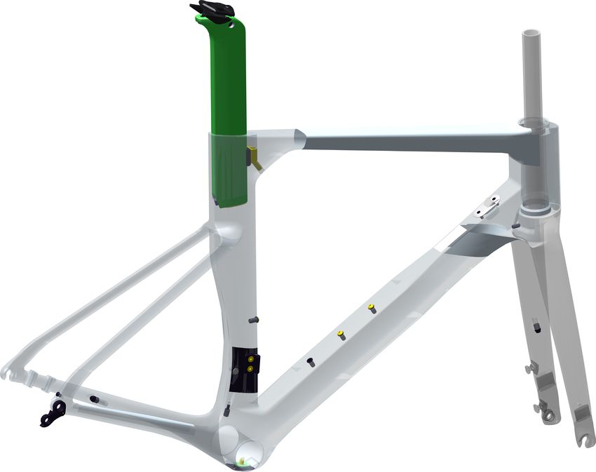
ENGLISH

 Explicit Definitions                                                            CONTENTS
 In this supplement, particularly important information is
 presented in the following ways:
                                                                 Safety Information............................... 2-5

                                                                 Technical Information........................ 6-18

   Indicates a hazardous situation which, if not avoided,        Replacement Parts...........................19-20
   may result in death or serious injury.

   NOTICE
   Indicates special precautions that must be taken to
   avoid damage.

 Cannondale Supplements
 This manual is a “supplement” to your Cannondale
 Bicycle Owner’s Manual.                                         Your Authorized
 This supplement provides additional and important               Cannondale Dealer
 model specific safety, maintenance, and technical
                                                                 To make sure your bike is serviced and maintained
 information. It may be one of several important
                                                                 correctly, and that you protect applicable warranties,
 manuals/supplements for your bike; obtain and read all
                                                                 please coordinate all service and maintenance through
 of them.
                                                                 your Authorized Cannondale Dealer.
 Please contact your Authorized Cannondale Dealer
 immediately if you need a manual or supplement, or
                                                                  NOTICE
 have a question about your bike. You may also contact
 us using the appropriate country/region/location                 Unauthorized service, maintenance, or repair parts
 information. See Contacting Cannondale in this                   can result in serious damage and void your warranty.
 supplement.

 You can download Adobe Acrobat PDF versions of any
 manual/supplement from our website:
 http://www.cannondale.com

                                                                 Contacting Cannondale
                                                                 Cannondale USA
                                                                 Cycling Sports Group, Inc.
   THIS SUPPLEMENT MAY INCLUDE PROCEDURES                        1 Cannondale Way, Wilton CT, 06897, USA
   BEYOND THE SCOPE OF GENERAL MECHANICAL                        1-800-726-BIKE (2453)
   APTITUDE.
                                                                 Cycling Sports Group Europe B.V
   Special tools, skills, and knowledge may be required.         Mail: Postbus 5100
   Improper mechanical work increases the risk of an             Visits: Hanzepoort 27
   accident. Any bicycle accident has risk of serious            7570 GC, OLDENZAAL, Netherlands
   injury, paralysis or death.                                   Tel: +41 61 551 14 80
                                                                 Fax:+31 54 151 42 40
   To minimize risk we strongly recommend that
   owners always have mechanical work done by an
   Authorized Cannondale retailer.

134921 Rev 2.                                                1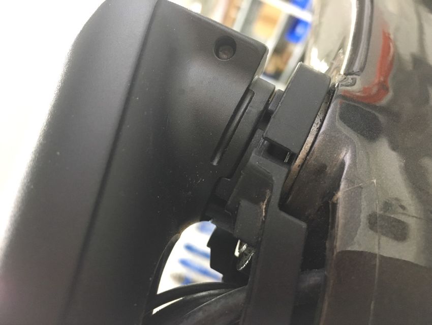
SYSTEMSIX - OWNERS MANUAL SUPPLEMENT

                                      SAFETY INFORMATION

 Important Composites                                         Inspection & Crash Damage Of
 Message                                                      Carbon Frames/Forks

   Your bike (frame and components) is made from               AFTER A CRASH OR IMPACT:
   composite materials also known as “carbon fiber.”
                                                               Inspect frame carefully for damage (See PART II,
   All riders must understand a fundamental reality            Section D. Inspect For Safety in your Cannondale
   of composites. Composite materials constructed              Bicycle Owner’s Manual. )
   of carbon fibers are strong and light, but when
   crashed or overloaded, carbon fibers do not bend,           Do not ride your bike if you see any sign of damage,
   they break.                                                 such as broken, splintered, or delaminated carbon
                                                               fiber.
   For your safety, as you own and use the bike, you
   must follow proper service, maintenance, and                ANY OF THE FOLLOWING MAY INDICATE A
   inspection of all the composites (frame, stem, fork,        DELAMINATION OR DAMAGE:
   handlebar, seat post, etc.) Ask your Cannondale
                                                               ·   An unusual or strange feel to the frame
   Dealer for help.
                                                               ·   Carbon which has a soft feel or altered shape
   We urge you to read PART II, Section D. “Inspect For        ·   Creaking or other unexplained noises,
   Safety” in your Cannondale Bicycle Owner’s Manual           ·   Visible cracks, a white or milky color present in
   BEFORE you ride.
                                                                   carbon fiber section
   YOU CAN BE SEVERELY INJURED, PARALYZED
   OR KILLED IN AN ACCIDENT IF YOU IGNORE THIS                 CONTINUING TO RIDE A DAMAGED FRAME
   MESSAGE.                                                    INCREASES THE CHANCES OF FRAME FAILURE,
                                                               WITH THE POSSIBILITY OF INJURY OR DEATH OF
                                                               THE RIDER.

 Intended Use
                        The intended use of all models
                        is ASTM CONDITION 1,
                        High-Performance Road.                     YOU CAN BE YOU SERIOUSLY INJURED,
                                                                          PARALYZED OR KILLED
                                                                       IF YOU IGNORE WARNINGS.

   Please read your Cannondale Bicycle Owner’s
   Manual for more information about Intended Use
   and Conditions 1-5.

134921 Rev 2.                                             2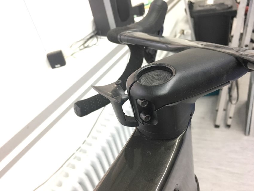
ENGLISH

 Disc Brakes on Road Bikes                                              Tightening Torques
                                                                        Correct tightening torque for the fasteners (bolts,
                                                                        screws, nuts) on your bicycle is very important to your
                                                                        safety. Correct tightening torque for the fasteners is
                                                                        also important for the durability and performance of
   Relative to conventional rim brakes, disc brakes are
                                                                        your bicycle. We urge you to have your dealer correctly
   less affected by water, do not wear or heat the rims
                                                                        torque all fasteners using a torque wrench. If you decide
   and therefore are more consistent. Disc brakes also
                                                                        to torque fasteners yourself always use a torque wrench.
   may be more powerful.
                                                                        Find Tightening Torque Information :
   To minimize risk of injury or accidents:

     · Understand that road bikes have a relatively
                                                                           The wide range of bicycle models and components
     small tire contact patch (part of the tire that
                                                                           used means that a listing of tightening torque would
     touches the road). In order to apply the brakes
                                                                           be out of date by the time it was published. Many
     safely and effectively, you may need more or less
                                                                           fasteners should be installed with a thread locking
     braking force in different situations. You need
                                                                           adhesive such as Loctite®®.
     to take into account various road and weather
     conditions that can affect traction.                                  To determine correct tightening torque and any
                                                                           adhesive application for a fastener we ask you to
     · Disc brakes are excellent, but not some kind of
                                                                           check:
     magic. Take some time riding your new disc brake
     road bike in lower risk circumstances to get used                     •      Many components are marked. On-product
     to the feel and performance of the disc brakes                               marking is becoming common.
     and tires.
                                                                           •      Torque specs in the component manufacturers
   YOU CAN BE SEVERELY INJURED, PARALYZED OR                                      instructions shipped with your bicycle.
   KILLED IN AN ACCIDENT IF YOU IGNORE THIS
   MESSAGE.                                                                •      Torque specs listed on the websites of
                                                                                  component manufacturers.

                                                                           •      With your dealer. Dealers have access to
                                                                                  current data and have experience with correct
                                                                                  torque for most fasteners.

                                              The following symbols are used in this manual:
                                                Symbol                  Name              Description
                                                  NG
                                                      LI       NGLI-2 synthetic grease    Apply NGLI-2 synthetic grease.
                                                         -2

                                                 CR
                                                   B-
                                                        GE
                                                           L
                                                                     Carbon gel           Apply carbon gel (friction paste) KF115/

                                                                  Medium-strength
                                                      2         removable thread lock
                                                                                          Apply Loctite® 242 (blue) or equivalent.

                                                      6        Low-strength thread lock   Apply Loctite® 222 (purple) or equivalent.

134921 Rev 2.                                                  3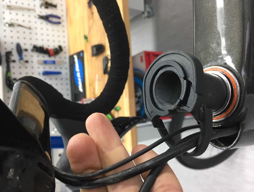
SYSTEMSIX - OWNERS MANUAL SUPPLEMENT

 Tire-to-Frame Clearance

   THE MINIMUM TIRE-TO-FRAME CLEARANCE
   MUST BE MAINTAINED.

        6mm

   If tire clearance is less than minimum specified, the
   rotating tire could come into contact with the frame
   causing the wheel to stop suddenly. This can throw a
   rider off the bicycle or result in a loss of control and
   crash. Frame damage due to tire rubbing frame can
   also happen. Not covered by the limited warranty.

   To measure clearance:

   1.    Inflate tire to maximum air pressure as
         indicated on the tire sidewall.

   2.    Measure the space between the tire and
         frame. Take measurement along the full
         length of possible interference. See arrows.

   3.    If the measured clearance is less than
         specified, the tire is not compatible and must
         not be used.

   YOU CAN BE SEVERELY INJURED, PARALYZED
   OR KILLED IN AN ACCIDENT IF YOU IGNORE THIS
   WARNING.

134921 Rev 2.                                                 4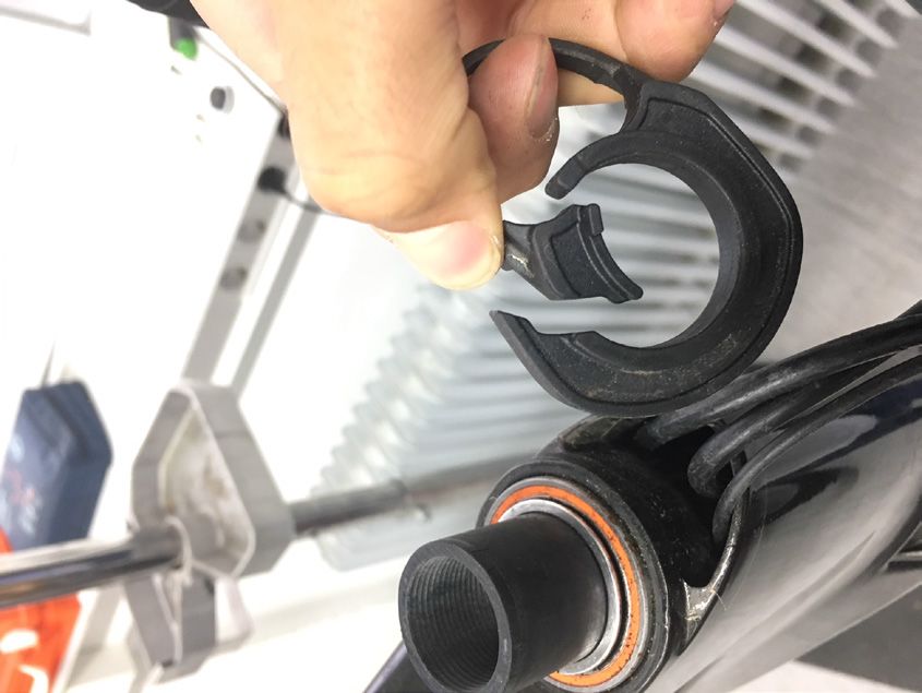
ENGLISH

 Trainers                                                             Water Bottles
 If you ride a trainer that requires removal of the front             Side impacts to a water bottle or cage can result in
 wheel and clamps the fork dropouts: Be sure your fork                damage to threaded inserts due to the leverage on
 quick release is tight! Relative movement will wear parts,           a very small area. In a crash, certainly the last thing
 weaken and damage your bike.                                         you should be worried about is saving the threaded
                                                                      inserts in your frame. However, when you are storing or
 If you ride a trainer that holds the bike up by clamping
                                                                      transporting your bike, take steps to prevent situations
 the rear quick release between two cones: Take off
                                                                      where a water bottle may be hit or bumped by a strong
 the lightweight quick release that came with your
                                                                      force that would cause damage. Remove bottle and
 bike. Substitute a heavy, classic all steel quick release
                                                                      cage when you are packing your bike for travel.
 and clamp it tight! Relative movement will wear parts,
 weaken and damage your bike. Note that many modern                   Periodically check the attachment of the bottle cage;
 quick releases will not fit the clamping cones in this kind          tighten the cage bolts if necessary. Don’t ride with a
 of trainer because their shapes are incompatible.                    loose bottle cage. Riding with loose cage bolts can
                                                                      produce a rocking motion or vibration of the attached
 For thru axles, make sure you follow the trainer
                                                                      cage. A loose cage will damage the insert and possibly
 manufacturer instructions for the use of any required
                                                                      lead to the inserts to pull out.
 adapters.
                                                                      It may be possible to repair a loose insert, or install
 Be particularly cautious with a carbon frame or fork.                another insert only if the frame is undamaged.
 Carbon is relatively soft, not abrasion resistant. If there is       Replacement requires the use of a special tool. If you
 any relative movement, carbon will wear quickly.                     notice damage to the threaded insert, please ask your
                                                                      Cannondale Dealer for help.
 If you ride a trainer a lot, consider using an old bike:
 Corrosion from sweat will take its toll. Weight is
 irrelevant. Save wear on your expensive components.                  Building Up A Frame Set
 Ask you dealer for help with trainers, the right one                 Before building up a frame set, consult with your
 and the correct way to use it.                                       Cannondale Dealer and the component manufacturers,
                                                                      and discuss your riding style, ability, weight, and interest
                                                                      in and patience for maintenance.
   NOTICE
                                                                      Make sure the components chosen are compatible with
   TRAINERS - Improperly mounting a bike in a trainer,                your bike and intended for your weight and riding style.
   or using one that is not compatible with your
   particular bike frame can cause serious damage.                    Generally speaking, lighter weight components have
                                                                      shorter lives. In selecting lightweight components, you
   WATER BOTTLES - An impact, crash, or loose bottle
                                                                      are making a trade-off, favoring the higher performance
   cage can result in damage to your frame.
                                                                      that comes with less weight over longevity. If you
   This kind of damage is not covered by the                          choose more lightweight components, you must inspect
   Cannondale Limited Warranty.                                       them more frequently. If you are a heavier rider or have a
                                                                      rough, abusive or “go for it” riding style, buy heavy duty
                                                                      components.

                                                                      Read and follow the component manufacturers
                                                                      warnings and instructions.

134921 Rev 2.                                                     5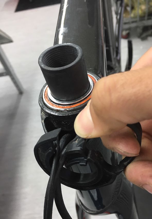
SYSTEMSIX - OWNERS MANUAL SUPPLEMENT

                                   TECHNICAL INFORMATION
 Frame Specification

  Item                                     Specification
  Frame                                    142mm, 700c
  Head Tube                                UPR: 1 -1/8", LWR: 1-1/4"
  Headset                                  Integrated, 1-1/8" - 1-1/4"
  Bottom Bracket: Type/ Width              PF30 / 73mm
  Front Derailleur                         Brazed-on, Down-Pull
  Seat Post: Dia./Binder                   KNØT Seatpost, Internal Wedge
      Tire Size/ Max. Tire Width           700C x 30mm (as measured)
  Front Tire Min. Clearance                6mm (See page 4)
     Min. Seat Post Insert                 65mm
  Rear Brake: Mount Type/Dia.              Flat Mount, 140/160mm
  Rear Brake: Fixing Bolt Length           Shimano 38.0mm / Converter 38.1mm
                                           Speed Release, Double Lead, M12x1.0 , FR: 100 x12mm, 119mm
  Axles: Type/Length
                                           Length, RR: 142 x12mm, 165mm Length,
      Intended Use:                        ASTM CONDITION 1, High-Performance Road
     Max. Weight Limit: Total (rider+all   (285lbs / 129Kg)
  equipment):

 Bottom Bracket Cable Guide

                                                                           2

                                                                                      RB
                                                           1
                                                                                     FD
                                                                                    RD

                                                  2
                                                3 N·m

                                                                               1.   3M Pad
                                   3                                           2.   Guide
                                                                               3.   Cover
                                              2 N·m

134921 Rev 2.                                      6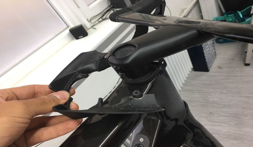
ENGLISH

 Geometry

    A       Seat Tube Length
    B       Top Tube Horizontal
                                                                                                       B
    C       Head Tube Angle
    D       Seat Tube Angle                                                                                O
    E       Standover
    F       Head Tube Length                                                                                               F
                                                                             Q
    G       Wheelbase                                                                                                              N
    H       Front Center                                                                A
                                                                                                75mm

    I       Chain Stay Length                                                                      E
    J       Bottom Bracket Drop
    K       Bottom Bracket Height
                                                                                            D                        C
    L       Fork Rake
    M       Trail                                                                                                              L
    N       Stack
                                                                        J           I                          H
    O       Reach                                               K

                                                                                                           G                   M

 Dimensions = centimeter

        cm              47                 51            54                  56                   58                60              62
        A              38.5               43.3          48.2                 53                  55.3              57.7             60
        B              51.4               52.9          54.4                 56                  57.6              59.2            60.9
        C              71.2°                *           73.0°                *                     *                 *                 *
        D              74.5°             74.1°          73.7°               73.3°               72.9°              72.5°           72.1°
        E               68                72.3          76.2                79.8                 82.1              84.3            86.3
        F               8.8               11.4          12.8                14.9                 17.2              19.3            21.4
        G              97.4               98.9          97.5                98.7                 100               101.2           102.4
        H              58.2               59.5          58.1                59.3                 60.5              61.7            62.9
        I              40.5                 *            *                   *                     *                 *                 *
        J               7.9                7.4          7.2                  *                    6.9                *                 *
        K              26.1               26.6          26.9                 *                   27.1                *                 *
        L               5.5                 *           4.5                  *                     *                 *                 *
        M               5.8                 *           5.7                  *                     *                 *                 *
        N              50.0               52.0          54.0                56.0                 58.0              60.0            62.0
        O              37.5               38.1          38.6                39.2                 39.8              40.3            40.9

 All Specifications subject to change without notice.
 * Indicates same.

134921 Rev 2.                                                       7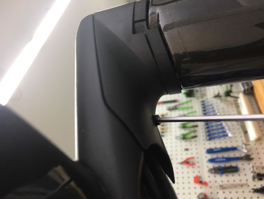
SYSTEMSIX - OWNERS MANUAL SUPPLEMENT

 Rear Derailleur Mount                                           Front Derailleur Mount
                                                                                                                         1

                                                                                                         7
                a
                                                                                                             1
                                                                          5
                                    NGLI-2
                                                                                6
                2
                                                                                                                             2

                                                                                                                             2
                                                                                                                         4 N·m
        2                                                             4
      2 N·m
                                             1
                                                                      3

 1.   RD Hanger                a.   Frame cable/wire exit        1.       FD Mount                  5.   Grommet, wire
 2.   Screw                                                      2.       Screws                    6.   FD ST Plug
                                                                 3.       FD Cable Stop             7.   Plugs
                                                                 4.       FD Cable Plug

 To replace:
 Remove the rear axle.                                           Serial Number
 Remove the mounting screws and remove the old
 hanger from the dropout. Clean the area around the
 dropout and inspect the frame carefully for any cracks or
 damage. If you find damage have the frame inspected
 by your Cannondale Dealer .                                                                                     1

 If the dropout is un-damaged, apply a light film of
 grease between the frame and mount. This will help
 minimize any noise or “creaking” that might result from
 very slight movement between the dropout and hanger
 during movement of the derailleur.

 Slide the new hanger onto the dropout. Apply Loctite®
 242 (or medium strnegth thread lock) to the screw
 threads and tighten to the specified torque.

                                                                 The serial number is located on the bottom bracket. It
                                                                 is a 7-character barcode (1). Use this serial number to
                                                                 register your bike.

                                                                              To register your bike: go to the Product
                                                                              Registration section of our website at
                                                                              www.cannondale.com

134921 Rev 2.                                                8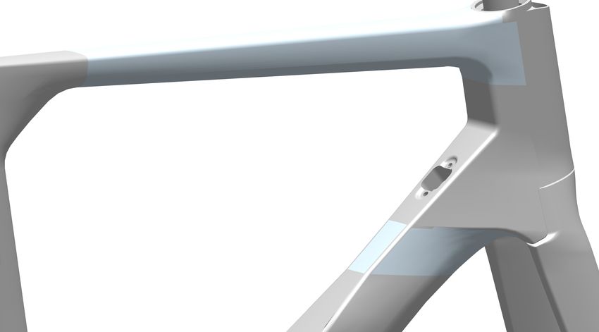
ENGLISH

 Bottom Bracket - BB30A, 73mm (PressFit)

                                                                             DRIVE                        NON-DRIVE

                                                                                               73mm
                                                                                     34.0mm              39.0mm

                2

                                                                   46mm
                                                                   42mm
                                                                   30mm
    3

                                                                               7mm

                                                    1

 Maintenance                                                   Follow the manufacturer’s instruction for assembly and
                                                               installation of the bearing system. Use a headset press
 In general, you should inspect the condition of the           such as Park Tool HHP-2. See http://www.parktool.com/
 bearings annually (at a minimum) or anytime the crankset      product/bearing-cup-press-HHP-2. Select appropriate
 assembly is disassembled, serviced, or if a problem is        press and adapters to ensure that force is only applied to
 indicated.                                                    the cup and not the bearing inside. Press until both cup
                                                               flanges are mated to the BB shell edge.
 To inspect, when the crankset is removed, rotate the inner
 bearing race of both bearings; rotation should be smooth,
 and quiet. Execesssive play, roughness or corrossion           NOTICE
 indicates a damaged bearing.
                                                                Consult with your Cannondale Dealer on the quality and
 Removal                                                        compatibilty of any proposed replacement component.
                                                                Make sure the PressFit BB30 system is intended for use
 To avoid serious damage to the frame, it is important to       with with a 46 mm I.D. BB shell. Confirm actual part
 remove bearing systems very carefully using proper tools       dimensions with a micrometer.
 indicated by the manufacture’s service instructions. Make
 sure the bearings (cup or adapter parts) are driven out        Do not over-tighten PF30 cup assembly, doing so can
                                                                result in damaging frame structure.
 squarely and evenly from inside the shell! Do not pry
 components from shell.                                         Do not use chemical solvents to clean. Do not remove
                                                                frame material or use surfacing tools on bottom bracket
 Replacement                                                    shell.
 PressFit BB30 bearings are not removable from the              Frame damage, caused by improper components,
 adapters or cup systems that are pressed into the frame        component installation or removal is not covered by
 bottom bracket shell. Therefore, damaged bearings must         your warranty.
 be removed and replaced as new entire sets. Before
 installing any new bearing units into the shell, thoroughly
 clean the inside surface of the bottom bracket shell with a
 clean dry shop towel. Also, make sure both bearing units
 and the BB shell surfaces are clean and dry. Do not apply
 grease to either.

134921 Rev 2.                                              9
SYSTEMSIX - OWNERS MANUAL SUPPLEMENT
Seat Post
Maintenance Be sure to replicate the angled cut on the seat post if its
length is changed. See illustatration.
Periodically, remove the seat post and the clamp
assembly to clean, inspect for damage and renew the
application of grease and carbon gel. NOTICE
A seat post should not be bottomed out inside the
Removal frame at any time. Have your Cannondale Dealer
size the seat post appropriately.
To remove the seat post, use a 4mm hex key to turn the
wedge bolt counter-clockwise to loosen it. When bolt
is loose simply lift the seat post up out of the seat tube. If the seat post must be cut, use a cutting guide and a
Then lift out the seat binder assembly out of the frame carbon saw blade. Lightly sand the edges of the cut seat
socket. tube with light sandpaper. Re-mark the minimum insert
line on the post.
Installation BE SURE TO REMOVE ANY INSTALLED BATTERY
Before inserting the seat post into the frame, use a BEFORE CUTTING A SEAT POST.
clean shop towel to wipe out any residual carbon gel
paste from the inside the seat tube. Do not use any
spray cleaners or solvents. Apply fresh carbon friction
gel to the seat post and place a little bit inside the seat
tube. Clean the wedge assembly and lightly grease the THE SEAT POST MUST ONLY BE CUT BY A
parts. Insert the loosened asembly into the frame, then PROFESSIONAL BIKE MECHANIC. Incorrectly
carefully insert the seat post into the frame. cutting the seat post can result in damage leading
Set the saddle height, and tighten the clamp bolt to the to an accident.
specified torque with a torque wrench.
Insert Limit & Sizing a
Seat Post Adjustment
The minimum insert depth the seat post must be 1. Insert 4mm hex through the underside seat tube
inserted into the frame is 65mm. This length is marked opening as shown.
by a line on the seat post.
2. Loosen the binder screw sufficient to move the seat
The total length of seat post that may be inserted will post up or down.
vary with the frame size and should be checked in each 3. Set the seat post position.
frame. A large size frame will accomodate more seat
post length than a small size frame. 4. Tighten the binder screw to the specified torque.
To check the depth, carefully slide a seat post into the
frame until it stops; then lift it up 5mm. To remove binder:
1. Loosen the binder with a 4 hex key and lift out the
seat post.
2. Remove the binder assembly through the seat tube
opening.
134921 Rev 2. 10ENGLISH
2
6 N·m
1. Seat Post
2. Seat Binder Assy.
3 Di2 Battery 25mm
9mm
1
3
2
Apply
carbon CRB-
GEL
gel
6 N·m
65mm
Minimum Insert
4mm
Maximum Insert
5mm NOTICE
Maximum Depth
Do not exceed the specified
torque. If you over-tighten
the binder bolt, you will
damage the binder, seat post
or the frame.
Suggested Tools:
For more information about carbon fiber seat posts, see also “Care
and Maintenance of Carbon Fiber Seat Posts” in your Cannondale Park Tool CSB-1
Bicycle Owner’s Manual.
134921 Rev 2. 11SYSTEMSIX - OWNERS MANUAL SUPPLEMENT
Seat Binder Assembly
NGLI-2 2 2
CRB- 4
GEL
3
1 NGLI-2
47cm
5
20mm
51cm
54cm
56cm
58cm
60cm
62cm
30mm
Periodically, to maintain the seat binder assembly, it is 4. Apply light grease only to the wedge (1) surface
recommended to: shown above. Don’t grease the wedge surface
that faces the seat post. Reassemble the wed-
1. Remove the seat post. ges. Apply Loctite® 242 to the retaining screw (2)
threads. Tighten the retaining screw lightly, then
2. Remove the binder assembly from the frame back it off one half of a turn so that the wedge
pocket (5). parts slide freely.
3. Disassemble the binder parts. Clean the binder 5. Apply grease to the binder screw (3) and thread
parts to remove any old grease and carbon gel/ 2-3 turns into the wedge (4).
friction paste. Use only acetone or isopropyl
alcohol and clean shop towel to clean. See also 6. Clean the frame pocket and the inside of the seat
WARNING, next page. tube. Use acetone or isopropyl alcohol. Wipe with
a dry shop towel. Insert the binder assembly into
the frame pocket.
7. Return the assembly into the frame pocket.
8. Install the seat post.
134921 Rev 2. 12ENGLISH
Seat Post - Shimano Di2 Battery
a
2
14 x1.60mm
3
b
1
4
5
6 7
Installation 8. The fit should be snug and the plug lip (b) should
contact the seat post end edge without distorting
The Shimano Di2 battery unit is retained inside the the outside of the seat post outer wall surface.
lower seat post with the expansion plug assembly - Test by shaking the seat post up and down to
Cannondale part number - K26149. The kit includes simulate riding vibration.
items 2, 4, 5, 6, shown above.
If the fit is secure, install the seat post. Remember
To install the battery in the seat post: to use carbon friction gel on the seat post and
tighten with a torque wrench.
1. Assemble O-ring (2) into battery groove (a).
Only if the fit is loose, remove the battery/
2. Pass battery cable (7) through center hole in grommet combination and insert the expander
grommet (5). plug (4) into the grommet from the opposite side
3. Connect cable (7) end into battery (3). as shown.
4. Insert slotted battery retainer plug (6) onto cable The seat post should always be a slide fit into the
(7) and press expander plug into grommet (5). frame and installation, adjustment, or removal
should not be difficult.
5. Slide grommet (5) onto battery (3).
6. Clean the inside opening of the seat post (1) end
with a clean shop towel dampened with isopropyl
alcohol.
• Wear safety glasses and hand protection
7. Insert the battery/plug combination into the end when performing any work.
of the seat post. • Acetone and isopropyl alcohol are
flammable liquids. Handle carefully. Wipe up
Do not use any grease or lubricant on the plug chemical spills immediately.
or inside the seat post.
134921 Rev 2. 13SYSTEMSIX - OWNERS MANUAL SUPPLEMENT
Headtube
1
50° 50°
4
2
1. Head tube routing inlet
2. Fork brake hose inlet
3 3. Steering stop pin
4. Down tube cable port
NOTICE
To prevent damaging the brake hoses or Di2 wires,
the steering stop pin (3) limits steering to 50 degrees
left and 50 degrees right. This is more than enough
steering for normal riding. This high-strength pin is
permanently anchored in the frame. Overload (due
to e.g. crash, etc.) may damage frame, fork or pin and
is not covered by the limited warranty.
134921 Rev 2. 14ENGLISH
KNØT SystemStem
4 N·m
K35009
3mm
2
MAX.
5 N·m
55mm
7.5mm
12.5mm
• The KNØT stem supports internal cable and wire routing.
• Assembly of spacers is explained on the following pages.
• Stem height may be set using combination of the 12.5mm and/or 7.5mm spacers.
• The Maximum Stack Height of the stem is 55mm. The example above depict 2x 12.5mm spacers and 4x 7.5mm
spacers, resulting in 55mm.
• The KNØT stem is to be used only with the Cannondale SystemBar handlebar.
• Use only the Cannondale SI Compression plug K35009.
134921 Rev 2. 15SYSTEMSIX - OWNERS MANUAL SUPPLEMENT KNØT Stem Spacers Spacers can be flexed open to allow spacer assembly / disassembly without disconnecting cables. Bend spacer inwards to route cables through first slot, then route cables through the second slot. Assemble spacer on steerer tube. Spacers and stem have interlocking feature to ensure alignment. 134921 Rev 2. 16
ENGLISH

   Hinge covers together and slide them over the stem
   body. Stem body and covers have interlocking features.

   Close right stem cover first, then rotate left stem cover in
   place and close around the stem body

   Assemble the stem covers with the M3 bolt (1Nm)

134921 Rev 2.                                                17
SYSTEMSIX - OWNERS MANUAL SUPPLEMENT

 Conventional Stem

                         K35009

    4 N·m
                                                                     7.5mm

                                 3mm

                             2
                           5 N·m
                                                              55mm
                             2 N·m

 Downtube Port

                                 Mechanical

         SRAM                                      Di2
         eTAP                                      Shimano
                                                   EW-RS910

134921 Rev 2.                                 18
ENGLISH
Replacement Parts - Frame/Fork
Frame size: “51,54,56,58,60,62”
C Frame size: “47”
2
6 N·m NOTICE
I
D
A
6 N·m
CRB-GEL 20 mm
30 mm
E
1X
4X 7.5mm
2X 12.5mm
B H
Di2
eTAP mech
Q Di2
J
O
2
2 N·m
G R
K
O
M N
2
4 N·m
2 P
F
E-tap 3 N·m
Di2
O L
2 N·m
ID Part Number Description ID Part Number Description
A K26129 KNØT System Seatpost 330mm J K34069 SystemSix Front Derailleur Plugs
B K26149 SystemSix Di2 Battery Mount K K33019 SystemSix Front Derailleur Mount
KNOT SystemSix Seatpost Clamp PF30 Bottom Bracket Cups And
C K34289 L KP197/SRM
HDWE Bearings
- K35039 Headset 1 1/8 to 1 1/4 with Split Ring M KB6180/ BB30 Bearing x2 Blue
D K35009 SL Compression Plug With Top Cap N K22037 BB30 Bearing x24 Blue
E K28009 SystemSix Stem Spacer Kit O K32048 Shift And Brake Grommets
F K32019 SystemSix Bottom Bracket CBL Guide P K83019 Speed Release Thru Axle 100x12
G K33009 Derailleur Hanger TA ST SS 070 Q K83029 Speed Release TA 142x12 165mm
H K32009 SystemSix Downtube CBL Guide R K34079 SystemSix Chainstay Protector
I K26139 KNØT System Aero Seat Binder
134921 Rev 2. 19SYSTEMSIX - OWNERS MANUAL SUPPLEMENT
Replacement Parts - KNØT System
2
F 5 N·m
A
D
CRB-GEL
2
5 N·m
B
B
1X
1 N·m
6
4X 2 N·m
7.5mm
E B
2
2X 5 N·m
12.5mm
C
G
H
ID Part Number Description ID Part Number Description
CP2009U1080 SystemStem BK 80mm CP2129U1038 KNØT SystemBar BK 380mm
CP2009U1090 KNØT SystemStem BK 90mm CP2129U1040 KNØT SystemBar BK 400mm
C
A CP2009U1010 KNØT SystemStem BK 100mm CP21219U1042 KNØT SystemBar BK 420mm
CP2009U1011 KNØT SystemStem BK 110mm CP2129U1044 KNØT SystemBar BK 440mm
CP2009U1012 KNØT SystemStem BK 120mm D K28018 SystemBar Mounting Hardware
CP2019U1080 KNØT SystemStem Cover BK 80mm E K28009 SystemSix Stem Spacer Kit
CP2019U1090 KNØT SystemStem Cover BK 90mm F K35009 SL Compression Plug With Top Cap
B CP2019U1010 KNØT SystemStem Cover BK 100mm G K12018 SystemBar Computer and Light Mount
CP2019U1011 KNØT SystemStem Cover BK 110mm H K12008 SystemBar Comp and Light Insert
CP2019U1012 KNØT SystemStem Cover BK 120mm
134921 Rev 2. 20WWW.CANNONDALE.COM © 2018 Cycling Sports Group SuperSlice Owner’s Manual Supplement 134921 Rev. 2 CANNONDALE USA CANNONDALE EUROPE CANNONDALE UK Cycling Sports Group, Inc. Cycling Sports Group Europe, B.V. Cycling Sports Group 1 Cannondale Way, Hanzepoort 27, 7570 GC, Oldenzaal, Vantage Way, The Fulcrum, Wilton CT, 06897, USA Netherlands +41 61 4879380 Poole, Dorset, BH12 4NU 1-800-726-BIKE (2453) servicedeskeurope@cyclingsportsgroup.com +44 (0)1202732288 www.cannondale.com sales@cyclingsportsgroup.co.uk
You can also read