USER MANUAL - TTMA-200 Trailer Truck Mounted Attenuator (MASH TL-3) - Gregory Industries
←
→
Page content transcription
If your browser does not render page correctly, please read the page content below
TTMA-200
Trailer Truck Mounted Attenuator (MASH TL-3)

 USER MANUAL
                 Gregory Industries, Inc.
  4100 13th Street, SW • Canton, Ohio 44710 • Phone 866-994-4929
                www.GregoryHighway.com
                    JANUARY 2021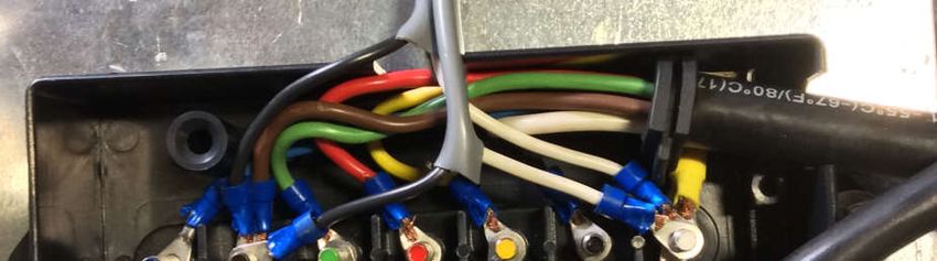
THIS PAGE LEFT BLANK INTENTIONALLY
FOREWORD
Thank you for your purchase of the TTMA-200 Trailer Truck Mounted Attenuator (MASH) from
Gregory Industries, Inc. (herein referred to as the TTMA-200). We are committed to providing our
customers with highway safety products offering the best performance and value for your money, as
well as the highest level of customer service.
The TTMA-200 is the latest addition to our highway safety products line. The TTMA-200 is an
AASHTO MASH 2016 Test Level 3 (TL-3) crash cushion designed for use with a support truck in
both stationary and moving work zones. The TTMA-200 is nearly identical to the predecessor
TTMA-100 which was one of the most innovative TMA’s in the market.
The TTMA-200 can be equipped to most vehicles 10,000 lbs. or heavier in your fleet within a matter
of minutes. The TTMA-200 has successfully passed all required crash tests (3-50, 3-51, 3-52, 3-53,
3-54) set forth by AASHTO MASH 2016 and is eligible for use on the National Highway System by
the Federal Highway Administration (CC-152). Versatility, reparability and ease of use are the keys
to the TTMA-200. We believe you will find the TTMA-200 a great value for your short or long-term
work zone solution.
This manual is a guide for operators through the operation and maintenance of the TTMA-200.
Please read and understand the recommendations contained in this manual thoroughly before using
the TTMA-200 and keep the manual available for future reference. If you have any questions or
comments regarding the operation and/or maintenance of this product, please contact us:
Telephone: (866) 994-4929 - Monday to Friday, 8:00 a.m. to 5:00 p.m. EST.
Email: Technical Support: TTMATechnicalSupport@gregorycorp.com
Sales & Distribution: TTMASales@gregorycorp.com
Mail: Gregory Industries, Inc. • 4100 13th Street SW • Canton, Ohio 44710
Online: For the most up to date version of our USER MANUAL visit our website
www.gregoryhighway.com
This manual has four sections:
TTMA Design and Major Components. Detailed in this section is an overview of the
TTMA-200 design and major components. Included are trailer and components, technical
specifications, and wiring instructions.
Operational Guidelines. Guidelines pertaining to the operation of the TTMA-200 are
located in this section such as minimum support truck weight, support truck attachment
structure, roll-ahead distances, connections, and other operational items.
Maintenance Guidelines: This section offers suggested routine maintenance of the TTMA-
200. How to keep the TTMA-200 in top operational condition.
Repair Guidelines. Includes discussion of impacts by an errant vehicle and the associated
repair and replacement of trailer parts.
i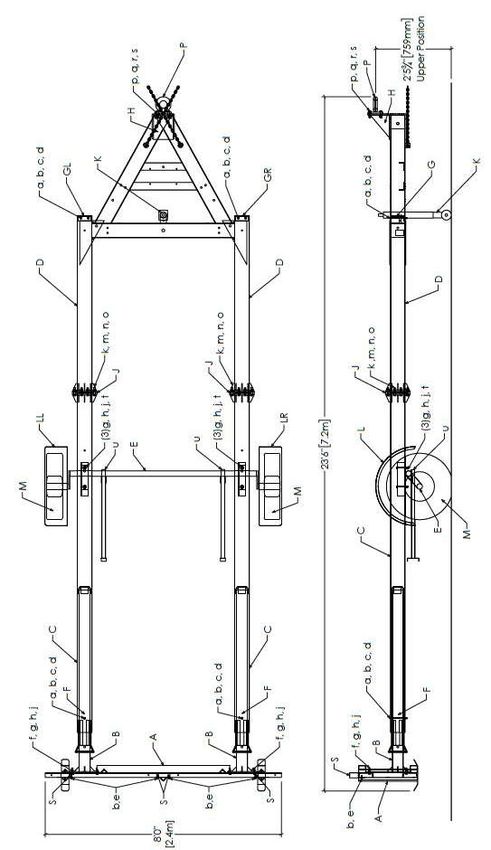
TABLE OF CONTENTS
                                                                                                                                                   Page

FORWARD............................................................................................................................................. i

TTMA-200 DESIGN AND MAJOR COMPONENTS ............................................................... 4-10
   General .............................................................................................................................................. 5
   Trailer and Component Listing .......................................................................................................... 5
   Technical Specifications ................................................................................................................... 6
   Wiring Instructions ....................................................................................................................... 8-10

OPERATIONAL GUIDELINES ................................................................................................ 11-14
   Initial Setup ..................................................................................................................................... 11
   Minimum & Maximum Weight of Tow Vehicle ............................................................................ 12
   Tow Vehicle Roll-Ahead Distances ................................................................................................ 12
   Attachment of TTMA-200 to Tow Vehicle .................................................................................... 12
   Roll-Ahead Distance Charts ............................................................................................................ 13
   Operation of TTMA-200 ................................................................................................................. 14

MAINTENANCE GUIDELINES ............................................................................................... 15-16
   Tire Wear Diagnostic Chart ............................................................................................................ 16

REPAIR GUIDELINES .............................................................................................................. 17-19
   TTMA-200 Repair .......................................................................................................................... 17
   Damage Assessment and Repair Packages ................................................................................ 17-19
       Nuisance Impact - No Apparent Damage to TTMA .................................................................... 17
       Level 1 Impact - Axle Assembly Not Detached ..................................................................... 17-18
       Level 2 Impact - Axle Assembly Detached, but No Damage to Trailer A-Frame .................. 18-19
       Level 3 Impact - Bursting Tube Reaches Trailer A-Frame .......................................................... 19
ARROW BOARD FRAME ........................................................................................................... 20-21
REPLACEMENT PARTS & COMPONENTS ................................................................................... 22
TECHNICAL ASSISTANCE .............................................................................................................. 23
LIMITATIONS AND WARNINGS.................................................................................................... 23
WARRANTY ..................................................................................................................................... 23
USER NOTES .................................................................................................................................... 24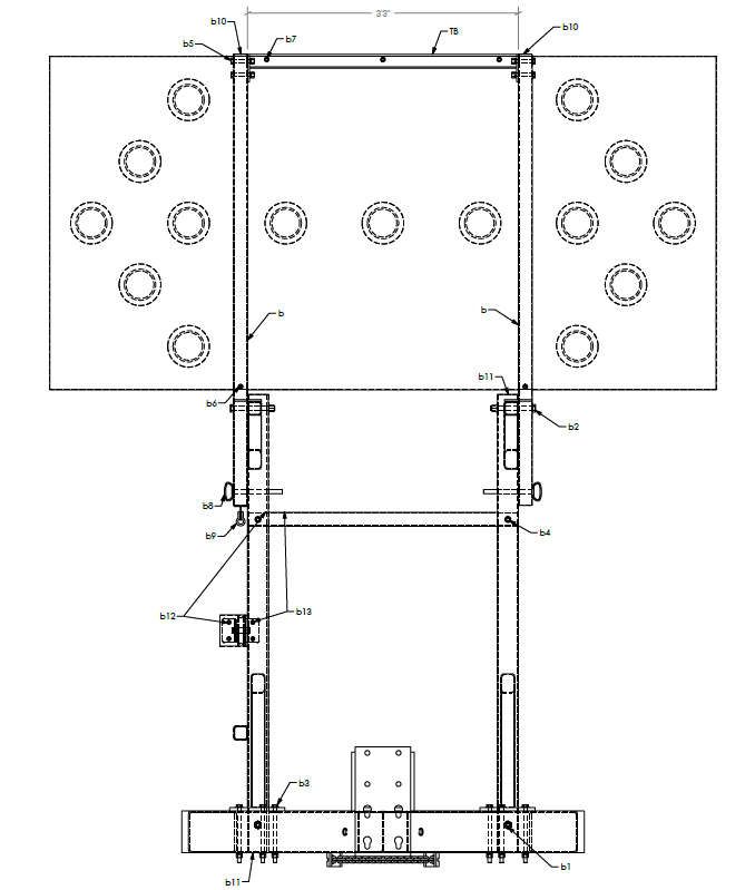
LIST OF FIGURES
  Figure                                                                                                                                   Page

(1) Schematic and Parts Layout of TTMA-200 .................................................................................... 4
(2) Photographs of RV and Heavy Duty Truck Plugs .......................................................................... 8
(3) Standard Wiring Layouts of RV and Heavy Duty Truck Plugs ...................................................... 8
(4) Wiring Junction Box TTMA-200 ..................................................................................................... 8
(5) TTMA-200 Wiring and Light Layout ........................................................................................... 10
(6) Mounting Positions of Lunette Ring ............................................................................................. 11
(7) Bursting of Energy Absorbing Tube ............................................................................................. 18
(8) Damage from Medium Speed Impact ............................................................................................ 18
(9) Arrow Board Frame (travel position) ............................................................................................. 20
(10) Arrow Board Frame (deployed position) ..................................................................................... 21

                                                       LIST OF TABLES
Table                                                                                                                                      Page

(1) Main Components of TTMA-200 ................................................................................................... 5
(2) Hardware Parts List ......................................................................................................................... 5
(3) Technical Specifications .................................................................................................................. 6
(4) Standard Wiring Layouts of RV and Heavy Duty Truck Plugs ...................................................... 9
(5) Torque Detail for Fasteners ........................................................................................................... 11
(6) Calculated Roll-Ahead Distances for Stationary Operation ......................................................... 13
(7) Calculated Roll-Ahead Distances for Mobile Operation (15 mph)................................................ 13
(8) Recommended Maintenance Schedule .......................................................................................... 15
(9) Tire Wear Diagnostic Chart ......................................................................................................... 16
(10) Repair and Replacement Parts ..................................................................................................... 22
TTMA-200 DESIGN AND MAJOR COMPONENTS

      Figure 1. Schematic and Parts Layout of TTMA-200

4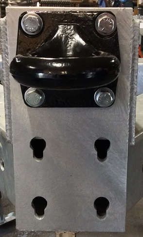
TTMA-200 DESIGN AND MAJOR COMPONENTS
GENERAL

                                            Trailer Components
ITEM            PART #                        QTY                                 DESCRIPTION
  A             T-200A                         1                                    Impact Head
  B              T-200B                        2                                  Bursting Mandrel
  C              T-200C                        2                            First Stage Energy Absorber
  D             T-200D                         1                                   Trailer A-Frame
  E              T-200P                        1                               MASH Axle Assembly
  F             T-NHRC                         2                     Plastic Guide Plates w/Shear Bolt & hdw
  G          T-200F/T-200G                     2                            End Caps (Driver/Passenger)
  H             T-200H                         1                           Hitch Assembly/Lunette Ring
  J              T-200J                        8                                        Spacer
  K             T-200K                         1                              Wheeled Jack Assembly
  L           T-200EF-L/R                      2                                  Fender (left/right)
  M              T-200T                        2                           Spare Tire w/rim (205/75D15)
 For a complete list of repair parts please refer to the index of this manual or contact your local distributor
                                    Table 1. Main Components of TTMA-200

                     Hardware Items (all hardware is Grade 5 Zinc Coated)
ITEM          PART #                QTY                               DESCRIPTION
  a             -                     6                      5/16”-18 x 7” Grade 5 Hex Bolt
  b             -                    12                              5/16” Flat Washer
  c             -                     6                         5/16” Heavy Lock Washer
  d             -                     6                              5/16”-18 Hex Nut
  e             -                    12                              5/16” Tech Screws
  f             -                     8                            1/2"-13 x 2” Hex Bolt
  g             -                    32                               1/2" Flat Washer
  h             -                    16                          1/2" Heavy Lock Washer
  j             -                    16                               1/2"-13 Hex Nuts
  k             -                    16                          9/16”-12 x 3” Hex Bolts
  m             -                    32                           9/16” SAE Flat Washer
  n             -                    16                         9/16” Heavy Lock Washer
  o             -                    16                              9/16”-12 Hex Nuts
  p             -                     4                         5/8”-11 x 2-1/2” Hex Bolts
  q             -                     4                            5/8” USS Flat Washer
  r             -                     4                          5/8” Heavy Lock Washer
  s             -                     4                                 5/8” Hex Nuts
  t             -                     4                  1-3/8” (1-1/2”  OD) Plastic Locking Plugs
  u             -                     2                             Square Tubing Plug
  v             -                     4                         1/2”-13 x 1-1/2” Hex Bolts
  w             -                     4                         1/2"-13 x 4-1/2” Hex Bolts
  x             -                     4                           5/8” SAE Flat Washers
 Hardware items listed for reference only. Hardware items supplied with each repair part as needed.
                                        Table 2. Hardware Parts List
                                                                                                                  5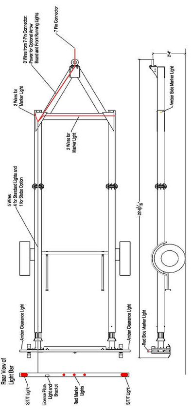
TTMA-200 Technical Specifications
Overall Dimensions
  Length ............................................................................................................................................ 23’ - 6”
  Width ................................................................................................................................................ 8’ - 0”
  Height (to top of impact head) ............................................................................................................. 39”
  Height (to top of light bar) ................................................................................................................... 43”
  Ground Clearance (to bottom of impact head) ...................................................................................... 13”

Capacity
  Trailer Weight .............................................................................................................................1,835 lbs.
  Approximate Tongue Weight (w/ Arrow Board Stand and Arrow Board) ....................................300 lbs.
  Minimum Support Truck Weight ..............................................................................................10,000 lbs.
  Maximum Support Truck Weight .............................................................................................. Unlimited

Pintle Hook
  Hitch ............................................................................... Lunette ring with no other structural attachment
  Capacity Rating (Minimum) .............................................................................................................8 tons
  Mounting Height (3 positions) ............................................................................................... 19.5” – 32.0”
  Hitch Plate (Hitch Mounting Structure) ......................................................................100 klbf (minimum)

Breakaway Axle
  Rating ..........................................................................................................................................2,200 lbs.
  Tire Size ................................................................................................................................... 205/75D15
  Rim Size .......................................................................................................................................... 15x5JJ
  Cold Tire Inflation Pressure ..............................................................................................................50 psi

Lighting
  Lighting ........................................................................................................................Integrated light bar
  Lighting Standard ................................................................................................................... FMVSS 108

Arrow Board Frame
  Arrow Board Frame ............................................................................................... 3" x 3" x 3/16" A500B
  Manual Winch ............................................................................................................................................

Construction
  Frame ..................................................................................................................................... Open design
  All energy absorbing components ....................................................................... 6” x 6” x 3/16" A500 B
  All structural members in impact system ............................................................... Hot-dipped galvanized
  Axle ................................................................................................................... Mid-mounted breakaway
  Fender ..................................................................................................................................... Full-fender

Safety Performance
  MASH 2016 required tests ......................................................................................................... AASHTO
  Support truck weight – MASH 2016 Tests 3-50, 3-51, 3-52, 3-54 ............................................ Unlimited
  Support truck weight – MASH 2016 Test 3-53 .................................................... 10,000 lbs. (minimum)
  Energy Absorbing System ............................................................................... Bursting Tube Technology
  FHWA Letter of Eligibility .............................................................................................................CC-152

Warranty
 Warranty against defects in material and workmanship .............................................................. One year

                                              Table 3. TTMA-200 Technical Specifications
6
TTMA-200 DESIGN AND MAJOR COMPONENTS
Table 3 presents the technical specifications for the TTMA-200, including:
Overall dimensions
Capacity of the TTMA-200
Capacity and mounting height of the Pintle hook
Axle, Tire, and Rim Capacity
Lighting specifications
Arrow Board Frame construction
Construction of the TTMA-200
Safety performance of TTMA-200
Warranty
7
WIRING INSTRUCTIONS
The TTMA-200 comes standard with a 7-pin Heavy Duty Truck Plug for connection to the tow vehicle. It
is necessary to determine the plug on the tow vehicle so the correct plug can be adapted to the TTMA-200.
The TTMA-200 can be adapted to fit an RV Plug as well as a 6-pin Heavy Duty Truck Plug. The shapes of
the plug types are distinguishable as shown Figure 2. The RV plug uses blades and both truck plugs uses
round pins.
RV Plug Heavy Duty Truck Plug (7-pin) Heavy Duty Truck Plug (6-pin)
Figure 2. Photographs of RV and Heavy Duty Truck Plugs
RV Plug Heavy Duty Truck Plug (7-pin) Heavy Duty Truck Plug (6-pin)
Figure 3. Standard Wiring Layouts of RV and Heavy Duty Truck Plugs
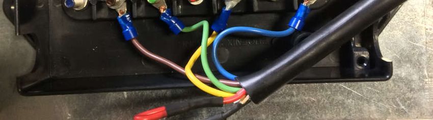
Figure 4. Wiring junction box TTMA-200
8WIRING INSTRUCTIONS (Cont.)
RV Plugs with Separate Brake Wire
Plug Labels
Function Trailer Wire Color Number Color
Common Ground White 1 White
Auxiliary Black 2 Black
Left Turn Yellow 3 Yellow
Brake Light Red 4 Red
Right Turn Green 5 Green
Tail/Marker Lights Brown 6 Brown
12V Power Supply Blue 7 Blue
Heavy Duty Truck Plugs
Plug Labels
Function Trailer Wire Color Number Color
Common Ground White 1 White
Brake Light Red 2 Blue
Tail/Marker Lights Brown 3 Green
12V Power Supply Blue 4 Black
Left Turn Yellow 5 Red
Right Turn Green 6 Brown
Auxiliary Black 7 (center)
Table 4. Standard Wiring Layouts of RV and Heavy Duty Truck Plugs
NOTE: The above wiring patterns represent standard wiring for the tow vehicle. Wiring patterns may need
modified if the tow vehicle does not use standard wiring. Please contact our technical services for assistance
at TTMATechnicalSupport@gregorycorp.com
Figure 3 shows the different standard wiring layouts for the RV plug and the heavy-duty truck plugs.
Figure 4 shows the schematic of the wiring details of the TTMA-200. The TTMA-200 is fully wired at the
time of delivery and this diagram is for reference purposes only. The only item that may require attention of
the user is the wiring of the trailer plug for connection to the tow vehicle.
9Figure 5. TTMA-200 Wiring and Light Layout 10
OPERATION GUIDELINES
INITIAL SETUP
The TTMA-200 should be delivered fully assembled. If there are problems with the delivered trailer, please
contact Gregory Industries, Inc. immediately.
Three items will require your attention prior to utilizing the trailer:
Check to make sure that there are no missing bolts and the bolts are tightened to the specific torque.
The following are the recommended torques to the bolts according to the bolt size:
Bolt Size (in) 5/16” 1/2” 9/16” 5/8”
Torque (ft-lb) 15 60 85 115
Torque (N-m) 20 81 115 156
Table 5. Torque Detail for Fasteners
Check to make sure the wiring of the trailer plug for connection to the tow vehicle is appropriate. As
mentioned on Page 8, there are two distinctly different wire plugs that are not compatible, one is the
RV plug and the other is the heavy-duty truck plug. Make sure that you have the correct type of
plug and that the plug is wired properly. Also, check to confirm that the lights are functioning
properly prior to putting the TTMA-200 into service.
Check to make sure the Pintle hook is mounted properly. Due to the wide variations in the frame
structures of different tow vehicles, there is not a single standard means of mounting the pintle hook
assembly to the frame of the tow vehicle. The major considerations in mounting of the pintle
hook are the strength of the attachment and the mounting height.
The Pintle hook assembly may be welded or bolted to the frame of the tow vehicle. Regardless of
the method of mounting or attachment to the tow vehicle, it is critical to ensure that the strength of
the attachment exceeds the rated capacity of the pintle hook with a wide margin of safety. It is the
obligation of the users to ensure that their particular pintle hook attachment system meets
these strength requirements. Figure 6 below shows the mounting positions of the lunette ring.
Figure 6. Mounting Positions of Lunette Ring
11MINIMUM AND MAXIMUM WEIGHT OF TOW VEHICLE
The minimum recommended weight for the tow vehicle is 10,000 lbs. gross vehicle weight (GVW) was
established during AASHTO MASH 2016 Test 3-53. This test, as specified by AASHTO MASH 2016 did
not use a vehicle blocked against forward movement. There is no specified maximum weight for the tow
vehicle. TTMA-200 crash tests (3-50, 3-51, 3-52) specified under AASHTO MASH 2016 were conducted
with the TTMA-200 attached to a tow vehicle that was blocked against any forward movement. By these
standards, the TTMA-200 can be towed by a vehicle with an unlimited amount of weight.
TOW VEHICLE ROLL AHEAD DISTANCES
One of the major safety concerns is the roll-ahead distance of the shadow vehicle when impacted by an
errant vehicle. When an errant vehicle impacts the tow vehicle with a TTMA-200 attached, it WILL roll
forward. It is therefore important to allow sufficient space between the tow vehicle and the workers so the
roll ahead of the tow vehicle would not pose any safety concern to the workers. Table 6 and Table 7 show
the estimated roll-ahead distances for rolling and stationary tow vehicles, respectively, as a function of
impact speed and weights of the support truck and impacting vehicle. The space between the support
vehicle and the workers should exceed the estimated roll-ahead distance under the prevailing operating
conditions. The following steps are provided to determine appropriate roll-ahead distance.
1. Assess the nature of the operation (i.e., moving or stationary operation). In a moving operation, the
tow vehicle is moving at slow speed, such as 15 mph. In a stationary operation, the shadow vehicle
is stopped with the parking brakes on. Use Table 6 for stationary operations and Table 7 for mobile
operations.
2. Select the weight that best approximates the actual weight of the tow vehicle: 10,000, 15,000,
24,000, 40,000, 60,000 or 80,000 lb. Note the weight of the support truck should include the
weights of items to be carried on the truck during the operation and the weight of the TTMA-200.
3. Select the range of prevailing speed of the traffic at the work zone: 45, 55 or 65 mph.
4. Select the weight of the impact vehicle to be contained: 10,000, 15,000, or 24,000 lb.
5. Select from the appropriate table the expected roll ahead distance
For example: If you are operating a tow vehicle with a gross weight of 15,000 lb as a stopped shadow
vehicle in an area where the operating traffic speed is 45 mph, and there are few if any large trucks in the
mix of traffic. Start with Table 6, select the appropriate values from above, and determine that the
maximum roll-ahead distance would be 11 ft. This is the distance from the front of the tow vehicle to the
work area that should be provided.
ATTACHMENT OF TTMA-200 TO TOW VEHICLE
The TTMA-200 is attached to the tow vehicle via a Pintle hook with a minimum capacity of 8 tons.
Verify the retaining pin for the pintle hook is properly locked to avoid accidental release of the Pintle
hook and lunette ring attachment of the TTMA-200
Make sure the TTMA-200 lights are connected to the tow vehicle and are operating properly
Ensure the safety chains properly secure the TTMA-200 to the tow vehicle.
The mounting structure where the pintle hook attaches should be capable of sustaining 100 klbf
(minimum) force at impact. Consult the hitch plate, vehicles manufacturer or engineer to ensure mount
integrity.
12Traffic Impact Vehicle Weight
Tow Vehicle
Operating
Weight 4500 lbs. 10000 lbs. 15000 lbs. 24000 lbs.
Speed
65 mph 38 ft. 103 ft. 152 ft. 216 ft.
10000 lbs. 55 mph 27 ft. 74 ft. 109 ft. 155 ft.
45 mph 18 ft. 50 ft. 73 ft. 104 ft.
65 mph 22 ft. 68 ft. 108 ft. 166 ft.
15000 lbs. 55 mph 16 ft. 49 ft. 77 ft. 119 ft.
45 mph 11 ft. 33 ft. 52 ft. 80 ft.
65 mph 11 ft. 38 ft. 65 ft. 111 ft.
24000 lbs. 55 mph 8 ft. 27 ft. 47 ft. 80 ft.
45 mph 6 ft. 18 ft. 32 ft. 54 ft.
65 mph 5 ft. 18 ft. 34 ft. 64 ft.
40000 lbs. 55 mph 4 ft. 13 ft. 24 ft. 46 ft.
45 mph 3 ft. 9 ft. 16 ft. 31 ft.
65 mph 3 ft. 10 ft. 19 ft. 38 ft.
60000 lbs. 55 mph 2 ft. 7 ft. 13 ft. 27 ft.
45 mph 2 ft. 5 ft. 9 ft. 18 ft.
65 mph 2 ft. 6 ft. 12 ft. 25 ft.
80000 lbs. 55 mph 1 ft. 5 ft. 9 ft. 18 ft.
45 mph 1 ft. 3 ft. 6 ft. 12 ft.
Table 6. Calculated Roll Ahead Distances for Stationary Operation
Traffic Impact Vehicle Weight
Tow Vehicle
Operating
Weight 4500 lbs. 10000 lbs. 15000 lbs. 24000 lbs.
Speed
65 mph 119 ft. 205 ft. 261 ft. 333 ft.
10000 lbs. 55 mph 97 ft. 158 ft. 198 ft. 247 ft.
45 mph 77 ft. 118 ft. 143 ft. 174 ft.
65 mph 93 ft. 161 ft. 211 ft. 278 ft.
15000 lbs. 55 mph 78 ft. 127 ft. 162 ft. 209 ft.
45 mph 65 ft. 97 ft. 120 ft. 150 ft.
65 mph 71 ft. 118 ft. 157 ft. 215 ft.
24000 lbs. 55 mph 62 ft. 97 ft. 124 ft. 165 ft.
45 mph 54 ft. 77 ft. 96 ft. 122 ft.
65 mph 56 ft. 86 ft. 112 ft. 155 ft.
40000 lbs. 55 mph 50 ft. 73 ft. 92 ft. 123 ft.
45 mph 45 ft. 61 ft. 74 ft. 95 ft.
65 mph 48 ft. 68 ft. 86 ft. 118 ft.
60000 lbs. 55 mph 44 ft. 60 ft. 73 ft. 96 ft.
45 mph 41 ft. 52 ft. 61 ft. 77 ft.
65 mph 44 ft. 59 ft. 73 ft. 97 ft.
80000 lbs. 55 mph 41 ft. 53 ft. 63 ft. 81 ft.
45 mph 39 ft. 47 ft. 54 ft. 67 ft.
Table 7. Calculated Roll Ahead Distances for Moving Operation (15 mph)
13OPERATION OF TTMA-200
Operation of the TTMA-200 is similar to many other trailers. Special attention should be given to the
following issues:
The TTMA-200 when deployed the entire TTMA-200 should be horizontal to the ground with the
impact head clearance to the ground at 13” +/- 1”
The TTMA-200 device does not have brakes. All braking will be dependent on the tow vehicle. Thus,
additional distance should be allowed for in braking and stopping of the tow vehicle.
Do not use the TTMA-200 for hauling. Objects on the trailer create a potential projectile hazard for
vehicles impacting the TTMA-200 and workers in the work zone.
Attachment of the TTMA-200 results in wider turns. Drivers should be aware of this need for wider
turning radius and adjust their driving accordingly.
Attachment of any trailer TMA will result in different handling for the tow vehicle while backing up.
Drivers should be aware of this difference in vehicle handling characteristics and adjust their driving
accordingly.
Tow vehicles should be equipped with headrests, lap belts and shoulder straps to provide proper crash
protection for the driver. Operators should adjust their headrest to contact the center of the head and
should wear seat belt and shoulder strap at all times.
Do not attach any item to the trailer or hitch without explicit approval from the manufacturer.
Contact Gregory Industries Technical Support for any question regarding attachments to the trailer
E-Mail: TTMATechnicalSupport@gregorycorp.com - Phone: (330) 477-4800
Verify that the retaining pin for the Pintle hook is properly locked to avoid accidental release of the
Pintle hook and/or the lunette ring attachment of the TTMA-200.
Make sure that the trailer lights are connected to the tow vehicle and operating properly.
Ensure that the safety chains properly secure the TTMA-200 to the tow vehicle.
This manual does not cover the operation of optional equipment such as arrow boards, variable message
signboards, and other approved hitch mounted equipment. Please see appropriate operating manuals
accompanying those devices for instructions.
14MAINTENANCE GUIDELINES
Proper maintenance of the TTMA-200 is critical to assure continued safe operation and long-term durability of
the device. The outside of the TTMA-200 should be washed periodically, particularly during winter usage, to
eliminate salt and other road contaminants. The inside of the frame should be washed annually. The end caps
(Item G) can be removed to allow rinsing the inside of the frame. Care should be taken with the wiring for the
side marker lights during this process. Note all critical parts of the TTMA-200 are hot-dip galvanized and require
minimal maintenance. The following preventive maintenance schedule is recommended:
Each
Item Function Required Weekly 3 Months 1 Year
Use
Lighting System Test that all lights are operational **
Check capacity and verify the retaining
Pintle Hook **
pins properly inserted
Safety Chains Check they are properly attached **
Mandrel Check the restraining bolts are not
Restraining missing, bent, or broken and tightened to **
Bolts specified torque of 15 lbs.
Check tightness of the 5/8" nuts / bolts to
Lunette Ring **
torque of 115 ft-lbs
Tire Inflation Ensure tires are inflated to 50 psi (Cold) **
Inspect for cuts, wear, bulging, etc.
Tire Condition Table 9 provides guidance of routine wear **
issues.
Inspect for cracks, dents, distortion or
Wheels **
other signs of wear
Inspect retroreflective material & ensure it
Chevrons **
meets requirements for deployment
Check the 9/16” splice bolts are not
Splice Bolts missing, bent, or broken and tightened to **
the specified torque of 85 ft-lbs.
Tighten to manufacturer specified torque
Wheel Nuts **
values
Check the ½” breakaway axle bolts are not
Breakaway
missing, bent, or broken and tightened to **
Axle Bolts
the specified torque of 60 ft-lbs.
Wheel Bearings Inspect for corrosion or wear. Clean and
**
and Cups repack
Check for cracks, call Gregory Industries
Frame Welds **
for instruction if cracks are detected
Torque Chart
Bolt Size (in) 5/16” 1/2” 9/16” 5/8”
Torque (ft-lb) 15 60 85 115
Torque (N-m) 20 81 115 156
TABLE 8. Recommended Maintenance Schedule
15Tire Wear Diagnostic Chart
Wear Pattern Cause Action
Adjust pressure to
Center Wear Over Inflation particular load per tire
catalog
Adjust pressure to
Edge Wear Under Inflation particular load per tire
catalog
Make sure load does not
Loss of camber or
Side Wear exceed axle rating.
overloading
Alignment may be needed
Even Wear Proper wear of tire Replace Tires
Check bearing adjustment
Cupping Out of balance
and balance tires
Wheel lockup & tire Avoid sudden stops when
Flat Spots
skidding possible and adjust brakes
TABLE 9. Tire Wear Diagnostic Chart
16REPAIR GUIDELINES
For impacts requiring repair and replacement of parts on the TTMA-200, Gregory Industries, Inc. offers
different parts packages depending on the extent of damage sustained by the unit. Parts packages are
available through Gregory Industries, Inc. or a TTMA-200 distributor in your area.
DAMAGE ASSESSMENT AND REPAIR PARTS PACKAGES
Inspect the TTMA-200 to assess the extent of the damage and the necessary repairs. Due to the simple
design of the TTMA-200, damages to the trailers are usually very evident. The TTMA-200 should always
be thoroughly inspected to assure everything is in proper working order prior to returning into
service.
The extent of damage to the trailer will vary greatly, depending on the nature and severity of the impact. It
would not possible to cover all situations that could potentially be encountered in real-world crashes. Thus,
the instructions are presented in general terms for the following levels of damage to the trailer.
Nuisance Impact – No apparent damage to TTMA-200 (5 mph impact)
Level 1 Impact - Energy absorbing tubes (Part C) bursted, but axle assembly (Part E) not detached.
Level 2 Impact - Energy absorbing tubes (Part C) bursted and axle assembly (Part E) detached, but
the bursting does not reach the trailer A-frame (Part D).
Level 3 Impact - Bursting reaches trailer A-frame (Part D).
Nuisance Impact - No Apparent Damage to Trailer
Inspect shear bolts (Part a) holding mandrels (Part B) in place with the energy absorbing tubes (Part
C). If the shear bolts are bent or broken, replace the bolts.
Inspect trailer lighting system for damage. If the lighting system sustains only minor damage, such
as a broken lens or light bulb, repair the damaged items, which may be purchased from automotive
supplies stores. Make sure that all the lights are working properly prior to returning the trailer to
service.
The following replacements parts are typically required for repair with this severity of damage
sustained by the trailer. T-NHRC (Shear Bolt, Nut, Washers and Plastic Guide Plates) per side.
The user may conduct replacement of the shear bolts and plastic guide plates for the mandrels and
repair of the lights in the field without involving the distributor or manufacturer.
Level 1 Impact – Energy absorbing tubes (Part C) bursted and axle assembly (Part E) not detached.
Replace energy absorbing tubes (Part C) and shear bolts (Parts a, b, c, d).
o T-200C (includes all hardware)
Inspect trailer lights for damage. If the lighting system sustains only minor damage, such as a
broken lens or light bulb, repair the damaged items, which may be purchased from automotive
supplies stores. Make sure all the lights are working properly prior to returning the TTMA-200 to
service. If the lighting system is severely damaged and no longer functional, replace the entire
lighting system.
17REPAIR GUIDELINES (Cont.)
o T-LIGHTBAR-12V (includes mounting hardware)
Inspect impact head (Part A) and mandrels (Parts B) for damage. For this severity of impact, it is
unusual for either the impact head or the mandrels to be damaged to the extent they are no longer
usable and need replaced. Check to make sure that the impact head and mandrels are not severely
bent and are properly aligned with the energy absorbing tubes. Replace as needed.
o T-200A (includes mounting hardware)
o T-200B (includes all hardware)
Inspect lunette ring and pintle hook for damage. For this severity of impact, it is unusual for either
the lunette ring or the pintle hook to be damaged to the extent they are no longer usable or need to
be replaced. Check to make sure that the lunette ring and the pintle hook are not severely bent and
can be hooked up properly.
o T-200H (includes mounting hardware)
Figure 7 Figure 8
Level 2 Impact - Axle Assembly Detached, but No Damage to Trailer A-Frame.
Replace energy-absorbing tubes (Part C) and shear bolts (Parts a, b, c, d, g and h).
o T-200C (includes all hardware)
Inspect the breakaway axle assembly (Part E) for damage. Replace axle if visibly bent. If the axle
is not damaged, but the push rods are bent, straighten out the push rods. Make sure that the push
rods are attached to the axle properly. If the axle is not damaged, but the fenders are severely bent,
replace only the fenders.
o T-200P (includes mounting hardware)
o T-200EF – (includes mounting hardware, specify left, right or both fenders)
Inspect trailer lights for damage. If the lighting system sustains only minor damage, such as a
broken lens or light bulb, repair the damaged items, which may be purchased from automotive
supplies stores. Make sure all the lights are working properly prior to returning the trailer to service.
If the lighting system is severely damaged and no longer functional, replace the entire lighting
system.
18REPAIR GUIDELINES (Cont.)
o T-LIGHTBAR-12V (includes mounting hardware)
Inspect impact head (Part A) and mandrels (Parts B) for damage. Check to make sure that the
impact head and mandrels are not severely bent and are properly aligned with the energy absorbing
tubes.
o T-200A (includes mounting hardware)
o T-200B (includes all hardware)
Inspect lunette ring and Pintle hook for damage. For this severity of impact, it is unusual for either
the lunette ring or the pintle hook to be damaged to the extent that they are no longer usable and
needs to be replaced. Check to make sure that the lunette ring and the pintle hook are not severely
bent and can be hooked up properly.
o T-200H (includes mounting hardware)
Level 3 Impact - Bursting Reaches Trailer A-Frame
For this high severity of impact, it is not advisable to repair the trailer. It is recommended the user consider
purchasing a new TTMA-200. The cost for the replacement parts would approach the price of a new trailer.
Extensive assembly will be required, which may pose some problems for someone not familiar with the
details of the trailer.
19Arrow Board Frame
The TTMA-200 can be equipped with heavy gauge steel arrow board framework for use with a variety of 4’
x 8’ arrow board panels or variable message boards.
The arrow board framework for the TTMA-200 was used with each successful test during the AASHTO
MASH 2016 testing.
NOTE: In the event an Arrow Board and Arrow Board Frame is not used on the TTMA a pair of ballast
plates must be used in their absence. The ballast plates provide the necessary tongue weight required for the
TTMA-200. Contact the manufacturer or distributor for pricing of ballast plates.
NOTE: Arrow Board/Arrow Board Frame should be moved to the travel position any time the TTMA-200
is being pulled over normal mobile work zone operating speeds. This will extend the life of the arrow-board
stand connections.
Figure 9. Arrow Board Frame (travel position)
20Figure 10. Arrow Board Frame (deployed position)
21Replacement Parts and Components of TTMA-200
Replacement Parts Description Weight (lbs.)
T-200A Impact Head & Hardware 240.00
T-200B Mandrel w/ Hardware (ea.) 120.00
T-200C Bursting Tube w/ Hardware (ea.) 127.00
T-200D Trailer A-Frame 505.00
T-200E Fender Bracket Light (specify driver or passenger side) 1.00
T-200EF-L/T-200EF-R Fender (Left or Right) 23.50
T-200F End Cap (Passenger) 1.75
T-200G End Cap (Driver) 1.75
T-200H Lunette Ring & Hardware 22.00
T-200J Spacer (package of 8) 2.00
T-200K Wheeled Jack Assembly 15.00
T-200K-WHEEL Jack Assembly (Wheel Only) 1.00
T-200L Safety Chains w/Hooks GR 70 (2 chains) – Standard Length 10.00
T-200LX Safety Chains w/Hooks GR 70 (2 chains) – Extended Length 11.00
T-200M 16” Hitch Extension 63.00
T-NHRC Shear Bolt, Nut, Washer & (2) Plastic Guide Plates 1.00
T-200P MASH Axle and 5 Lug Hub Assembly (only) 90.50
T-200R Battery Tray – Replacement/Upgrade 9.00
T-200S Spare Tire Mount w/ Hardware 20.00
T-200T Spare Tire w/ Rim (205/75D15) 37.50
T-200U Radial Tire (205/75D15) – Upgrade 37.50
T-200X T-Pin & Clip for Arrow Board Stand 1.00
T-200Y Wiring Harness (Each) - From Lightbar to Junction Box 9.00
T-200Z Reflective Tape for Bursting Tubes (2 per) 1.00
CHEVRONS Various Chevron Patterns (CALL) 8.00
T-200-LIGHTBAR 12 Volt Light Bar (includes hardware and brackets) 8.50
T-200-LIGHTBAR- MASH Mounting Brackets SS (Package of 4) with hardware 1.00
BRACKETS
TM-ABF Arrow Board Frame MASH 194.00
TM-WINCH Manual Winch for TM-ABF MASH 9.00
Table 10. Repair and Replacement Parts
Table 10 provides a list of parts and part numbers. Please refer to these part numbers and legends for
ordering spare or repair parts. Note this is not a complete parts list. Please inquire with the manufacturer,
distributor, or reseller of the TTMA-200 for a complete parts list and pricing.
22TECHNICAL ASSISTANCE
If you have any questions regarding inspection and assessment of damage to the trailer or required repair parts,
please contact your distributor or Gregory Industries, Inc. by telephone at
Telephone: (866) 994-4929 - Monday to Friday, 8:00 a.m. to 5:00 p.m. Eastern Standard Time.
Fax: (330) 477-0626
Email: TTMATechnicalSupport@gregorycorp.com
TTMASales@gregorycorp.com
Web Site: www.GregoryHighway.com
Mail: Gregory Industries, Inc.
4100 13th Street SW
Canton, Ohio 44710
In order for Technical assistance to better provide assessment of the TTMA-200 or required repair parts, it is
requested photographs be sent via email of the damaged TTMA-200 showing the overall damages, VIN tag and
damages to the specific areas or parts in question.
Limitations and Warnings
The TTMA-200 Trailer Truck Mounted Attenuator has been tested and evaluated per the recommendations of
the American Association of State Highway and Transportation Officials (AASHTO) Manual for Assessing
Safety Hardware (MASH) 2016.
The TTMA-200 Trailer Truck Mounted Attenuator is a Test Level 3 (TL-3) tested device capable of decelerating
and stopping lightweight vehicles (2,425 lbs.) [1100 kg] and heavyweight vehicles (5004 lbs.) [2270 kg] in
accordance with the criteria of MASH Tests 3-50, 3-51, 3-52, 3-53, 3-54 (62.14 mph/100 km/hr). FHWA Letter
of Eligibility CC-152.
Impacts that exceed the design capabilities described in this manual (vehicle weight, speed, impact angle) may
not result in acceptable crash performance as described in AASHTO MASH 2016, relative to structural
adequacy, occupant risk and vehicle trajectory factors.
One Year Limited Warranty
Gregory Industries, Inc. warrants the purchaser against any defects in materials and workmanship of the Trailer
Truck Mounted Attenuator (TTMA-200). Should the TTMA-200 prove to be defective in material and
workmanship during the period of this warranty, Gregory Industries, Inc. will repair and/or replace the defective
product free of charge. The period of the warranty shall commence on the date the purchaser puts the unit into
service and shall remain in effect for a period of ONE YEAR.
This warranty does not cover any failure of the TTMA-200 caused by misuse, abuse or material alteration of the
TTMA-200, or any negligence in connection with the installation, service, or use of this product. For proper
installation, maintenance, or use of this product refer to the User’s Manual, and the maintenance/service
checklist.
23NOTES 24
4100 13th St. S.W.
                     Canton, OH 44710

                     +1 (866) 994-4929
                  www.GregoryHighway.com

DISTRIBUTED BY:
You can also read