Engine power loss and low-speed rejected take-off, involving Airbus A320-232, registered VH-VFF - ATSB Transport Safety Report
←
→
Page content transcription
If your browser does not render page correctly, please read the page content below
Engine power loss and
low-speed rejected take-off,
involving Airbus A320-232,
registered VH-VFF
Brisbane Airport, Queensland, on 23 October 2020

 ATSB Transport Safety Report
 Aviation Occurrence Investigation (Short)
 AO-2020-058
 Final – ## August 2021
Released in accordance with section 25 of the Transport Safety Investigation Act 2003

Publishing information
Published by:            Australian Transport Safety Bureau
Postal address:          PO Box 967, Civic Square ACT 2608
Office:                  62 Northbourne Avenue Canberra, ACT 2601
Telephone:               1800 020 616, from overseas +61 2 6257 2463
                         Accident and incident notification: 1800 011 034 (24 hours)
Email:                   atsbinfo@atsb.gov.au
Website:                 www.atsb.gov.au

© Commonwealth of Australia 2021

Ownership of intellectual property rights in this publication
Unless otherwise noted, copyright (and any other intellectual property rights, if any) in this publication is owned by the
Commonwealth of Australia.

Creative Commons licence
With the exception of the Coat of Arms, ATSB logo, and photos and graphics in which a third party holds copyright,
this publication is licensed under a Creative Commons Attribution 3.0 Australia licence.

Creative Commons Attribution 3.0 Australia Licence is a standard form licence agreement that allows you to copy,
distribute, transmit and adapt this publication provided that you attribute the work.
The ATSB’s preference is that you attribute this publication (and any material sourced from it) using the following
wording: Source: Australian Transport Safety Bureau

Copyright in material obtained from other agencies, private individuals or organisations, belongs to those agencies,
individuals or organisations. Where you want to use their material you will need to contact them directly.

Addendum

    Page                Change                                                                          Date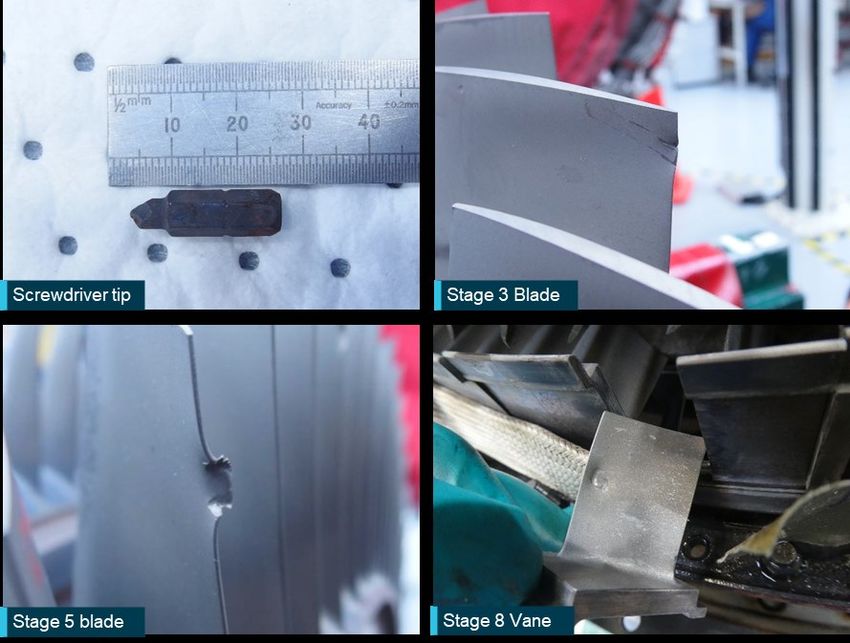
ATSB – AO-2020-058

Safety summary
What happened
On the morning of 23 October 2020, an Airbus A320-232 was being operated by Jetstar Airways
on a flight from Brisbane to Cairns, Queensland. As power was being applied for take-off, the crew
reported feeling a vibration and hearing a ‘popping’ noise that rapidly increased in frequency and
volume. At the same time, the aircraft diverged to the right of the runway centreline despite the
pilot flying applying full left rudder pedal deflection. The captain immediately selected reverse
thrust and brought the aircraft to a stop.
Some passengers onboard, a Brisbane air traffic tower controller, and flight crew of a following
aircraft all reported momentarily seeing flames coming out the right engine. The aircraft was taxied
back to the airport gate. Engineers then reported finding metallic debris in the tailpipe of the right
engine.
On disassembly of the engine, it was discovered the high-pressure compressor (HPC) had
sustained significant damage and a screwdriver tip was found in the combustion section.

What the ATSB found
The screwdriver tip was determined to have been in the engine for over 100 flights. The ATSB
concluded the tool bit had been left in the engine after maintenance and when the engine was
running, it entered the HPC leaving dents and nicks in numerous rotor blades and stator vanes. At
least two of these defects initiated fatigue cracks that resulted in a blade failing during the
occurrence take-off. The liberated blade caused greater damage to the HPC and the engine
surged.

What has been done as a result
As a result of the occurrence Jetstar Airways issued a Safety Alert to their maintenance
engineers, which highlighted the need for all tooling to be accounted for. They also conducted a
risk assessment to better understand the on-going risk.

Safety messages
Tool control is an important part of maintenance processes that ensures they do not lead to
foreign object damage. Small and seemingly insignificant tool components can, and have, caused
significant incidents or accidents. Tool control should extend to pseudo consumable items such as
screwdriver tips and drill bits.
Modern training methods include the use of high-fidelity training devices such as full motion flight
simulators. Their design aims to maximise the realism of an artificial environment. However, there
is a limit to their ability to replicate extreme events. Flight crew should be aware that the noise and
vibration from an actual engine failure may be greater than, or different to, that experienced during
simulator training and this could contribute to the effects of startle.

                                                  ›1 ‹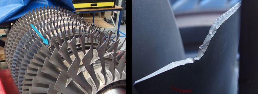
ATSB – AO-2020-058

The investigation
    Decisions regarding whether to conduct an investigation, and the scope of an investigation, are based on
    many factors, including the level of safety benefit likely to be obtained from an investigation. For this
    occurrence, a limited-scope investigation was conducted in order to produce a short investigation report,
    and allow for greater industry awareness of findings that affect safety and potential learning opportunities.

The occurrence
On the morning of 23 October 2020, an Airbus A320-232 was being operated by Jetstar Airways
on a flight from Brisbane to Cairns, Queensland. The first officer was the pilot flying and the
captain was the pilot monitoring. 1
After push back, the first officer taxied the aircraft for a planned take-off on runway 01L. The crew
completed the pre-take-off checks during the taxi in anticipation of a rolling start to the take-off.
After being cleared for take-off on approach to the runway, the aircraft was lined up and, without
stopping, the thrust levers were set for Flex. 2 The crew reported that as both engines spooled up
to the requested power setting, a vibration and ‘popping’ noise could be heard that rapidly
increased in frequency and volume. At the same time, the aircraft diverged to the right of the
runway centreline despite the first officer applying full left rudder pedal deflection. In response, the
captain immediately selected reverse thrust and brought the aircraft to a stop. The aircraft reached
a maximum ground speed of 30 knots.
Upon returning the thrust levers to idle, the vibration subsided and the popping stopped. The
aircraft instrumentation then sounded two master caution alarms and the Electronic Centralised
Aircraft Monitoring (ECAM) system 3 reported two messages for Engine No. 2 (right) ‘STALL’ and
‘EGT LIMIT EXCEEDANCE’. 4 The captain called for the cabin crew to move to stations. 5
The cabin crew relayed to the flight crew that passengers had seen flames coming from the right
engine. Both the airport tower controller and the flight crew of a following aircraft similarly reported
seeing flames coming from the rear of the right engine for a short period of time. The tower
dispatched Airport Rescue and Firefighting services, who observed no apparent abnormalities
with the aircraft.
The captain cancelled the flight and the aircraft was taxied back to the airport gate where both
engines were shut down. Immediately after the passengers had disembarked, engineers reported
finding small balls of metallic debris in the tailpipe of the right engine (Figure 1). A review of
recorded data indicated the right engine had surged.

1
      Pilot Flying (PF) and Pilot Monitoring (PM): procedurally assigned roles with specifically assigned duties at specific
      stages of a flight. The PF does most of the flying, except in defined circumstances. The PM carries out support duties
      and monitors the PF’s actions and the aircraft’s flight path.
2
      Flex is an engine thrust setting used for take-off which is below the maximum rated thrust for an engine. The engine
      thrust requested for a given take-off is calculated based on aircraft weight, flap setting, runway length available and
      ambient temperature, and is used to reduce engine wear.
3
      Electronic Centralised Aircraft Monitoring (ECAM) is a system that monitors aircraft functions and relays their status to
      flight crew. It also produces messages detailing failures.
4
      EGT – Exhaust Gas Temperature
5
      A ‘Call to stations’ is a notification via the public address system from the flight crew to the cabin crew that they are
      assessing an emergency situation and that an evacuation may be necessary. On receipt of this notification, cabin crew
      prepare by undertaking actions such as checking conditions outside their assigned door, maintaining control of
      passengers in the cabin and reporting any abnormal conditions to the flight crew.
                                                              ›2 ‹
ATSB – AO-2020-058

Figure 1: Debris in right engine tailpipe

Source: ATSB

Context
Engine Description
The IAE V2527-A5 engine is a variant of the V2500 family of engines. The two-spool, axial-flow,
high-bypass turbofan comprises low- and high-pressure stages. The low-pressure section consists
of a fan stage and four low-pressure compressor (LPC) stages (labelled booster stages)
connected to five low-pressure turbine (LPT) stages. The high-pressure section consists of ten
high-pressure compressor (HPC) stages (numbered 3 to 12) connected to two high-pressure
turbines (HPT) (Figure 2).

                                              ›3 ‹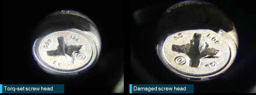
ATSB – AO-2020-058
Figure 2: IAE V2527-A5 engine station and stage numbering diagram
Source: IAE Training Manual.
Note: The low-pressure spool is shown in grey and the high-pressure spool in black.
An engine surge is caused by a loss of air compression on the inlet side of the engine. This can
be caused by disrupted airflow ahead of the engine, ingestion of foreign matter, excessive thrust
changes or an airflow disruption internal to the engine.
Regardless of the cause, the sudden breakdown in compression results in reversal of the flow and
violent expulsion of the previously compressed air out the inlet of the engine. The process is often
cyclic resulting in a vibratory noise. Additionally, disruption to the airflow can allow unburnt fuel to
escape the combustion chamber and ignite in the turbine section or tailpipe.
Post-flight Inspections
On wing inspection
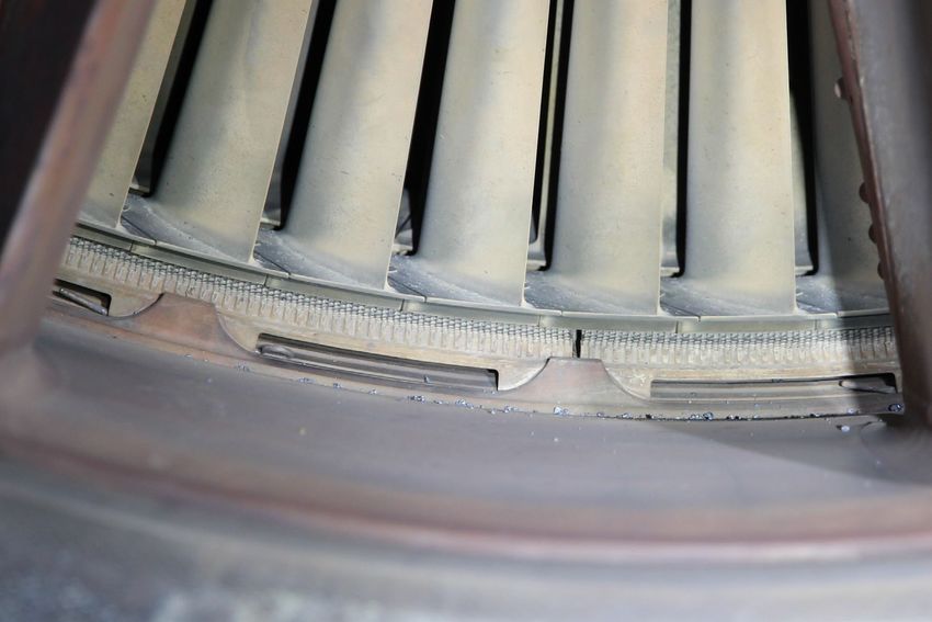
A borescope inspection of the right engine found there was damage to HPC stages 3, 5, 6, 7, 8
and 9 (Figure 3) consistent with foreign object damage (FOD). 6 As the damage was outside
maintenance manual limits, the engine was removed from the aircraft and sent for a teardown
inspection.
6
Foreign Object Damage (FOD) is any article or substance, alien to an aircraft or system, which could potentially cause
damage. The term FOD is used to describe both the foreign objects themselves and any damage attributed to them.
›4 ‹ATSB – AO-2020-058
Figure 3: Borescope image of stage 7 HPC and stage 8 stator vanes
Source: Jetstar
Teardown inspection
Upon disassembly of the engine, the following observations and anomalies were found:
• The fan blades and LPC contained no visible damage.
• The rear fairing to the LPC bleed valve mechanism was in place but had one Torq-set screw
with a damaged head. Although of an incompatible shape, testing showed that due to the
damage, the head would also accept a Phillips screwdriver tip (Figure 4).
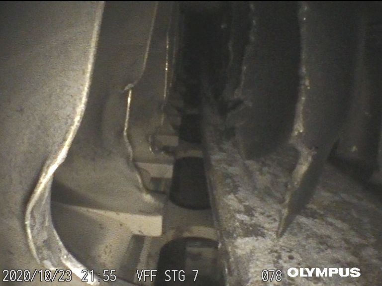
• In the HPC section, rotor blades (blades) and stators (vanes) in stages 3 and 4 contained
dents and minor tears.
• Approximately half of one stage 5 blade (Figure 5) and a whole stage 6 vane (Figure 6) were
missing and had failed due to cyclic fatigue. Some of the remaining stage 5 blades exhibited tip
curl, 7 dents and/or missing material.
• Four stage 7 blades and one stage 8 blade were missing and had failed due to overstress. In
this section all remaining blades and vanes exhibited hard body damage resulting in severe
bending and tearing to both leading and trailing edges. One stage 8 vane contained a
distinctive hexagon shaped dent (Figure 7).
• Damage after stage 8 was limited to minor dents and nicks with minimal damage occurring to
the final stage components.
• Bleed valve screens at stages 7 and 10 contained large amounts of metallic fragments.
7
Tip curl is a signature of compressor or turbine blades making contact with the engine casing.
›5 ‹ATSB – AO-2020-058
• Small metallic debris and a ¼” hexagon drive screwdriver tool bit (screwdriver tip) was found
between the combustion liner and engine case. The screwdriver tip was burnt/discoloured and
the tip eroded due to heat and mechanical damage (Figure 7).
• Nozzle Guide Vane (NGV) cooling passages contained small metallic debris.
• Two stage 1 HPT blades contained leading edge nicks attributed to material impacts.
• Small debris was found throughout the LPT.
Figure 4: Interstage screw heads
Source: Jetstar
Figure 5: Stage 5 blade fatigue failure
Source: Jetstar, annotated by the ATSB
Figure 6: Stage 6 vane fatigue failure
Source: Jetstar, annotated by the ATSB
›6 ‹ATSB – AO-2020-058
Witness marks on many components throughout the HPC matched the shape of the screwdriver
tip found in the combustion section (Figure 7).
Figure 7: Screwdriver tip and witness marks
Source: Jetstar
A failure analysis was conducted by an engine maintenance facility. The fractured stage 5 blade
showed minor leading edge mechanical damage at approximately half span, which initiated a
fatigue crack that propagated through approximately two-thirds of the chord. The remaining third
of the chord failed in material overstress.
The fractured stage 6 vane sustained a tear near the aerofoil root to a depth of approximately
10 per cent chord. This initiated a fatigue crack that ended 2 mm from the trailing edge with the
remaining material exhibiting a material overstress signature.
Both fatigue fracture surfaces displayed fine striations consistent with a high frequency load
spectrum, likely from aerodynamic vibrations. While no fatigue growth rate analysis was
conducted, based on similar occurrences, it was estimated the components took tens of flight
cycles to fail.
Aircraft maintenance program
The aircraft maintenance program required a fairing to be removed in the engine to lubricate the
LPC Bleed Valve Mechanism every 4,000 flight hours. The task was last accomplished 112 flight
cycles prior to the engine surge. This task occurred with many others as part of preparations to
return the aircraft to service after being parked for approximately 4 months.
The LPC Bleed Valve Mechanism task procedures contained specific highlighted caution notes
regarding the loss of any screws or other loose objects down the bleed duct. The note highlighted
that lost articles would progress to the HPC and break blades and vanes. This occurs because
during engine start and idle the bleed valve opens.
›7 ‹ATSB – AO-2020-058
Engine failure during take-off
Both flight crew commented that the event startled them due to its unexpected onset, the volume
of the popping noise and particularly the levels of vibration. Additionally, the pilot flying reported
that, despite the application of full left rudder, the aircraft still diverged to the right of the runway
centreline. Both pilots commented that the noise and vibration was far more severe than what they
had experienced during flight simulator training sessions when practicing for similar types of
events.
Flight crew training includes many different failure scenarios. Being a particularly critical phase of
flight, take-off is trained for extensively including engine failures that involve high-speed rejected
take-offs (RTO) and post V1 flight continuations. 8 One crewmember commented they had never
performed a low-speed RTO with engine failure.
For a high-speed engine failure, crews are trained to recognise the failure and maintain runway
direction through use of the rudder, which is effective at speeds above VMCG. 9 The take-off is then
either continued or rejected. If rejected, the thrust asymmetry is reduced by idling the remaining
engine/s.
Low-speed RTOs are those which occur below VMCG where the aircraft’s rudder is not effective
enough to counter the large thrust asymmetry and thus the aircraft will diverge from the runway
centreline uncontrollably if continued. This situation is countered by differential braking and
promptly returning the engines to idle, thereby reducing or nullifying the thrust asymmetry.
Low-speed RTOs, while considered less dangerous because they occur at lower speeds, involve
a loss of directional control. Lateral divergence from the runway centreline can be larger than for a
high-speed engine failure (>VMCG) and can cause considerable damage if the aircraft departs the
side of the runway.
Related Occurrences
ATSB investigation (199800615)
On 28 February 1998, at a height of about 100 ft after take-off, the crew of a Boeing 767 reported
hearing a series of loud bangs and the right engine exhaust gas temperature indicator rose rapidly
into the red range. The right thrust lever was retarded to idle, resulting in the temperature
indications returning to normal. ATC also observed a series of flashes from the right engine as the
aircraft departed and declared a local emergency. The crew returned the aircraft to the airport and
landed without further incident.
An internal borescope inspection revealed extensive damage to blades of the thirteenth
compressor stage. The engine was subsequently removed for further inspection, resulting in a
replaceable Philips screwdriver tip being found in the core of the engine.
The operator reported that the incident occurred on the first flight after the aircraft had undergone
an 'A' maintenance check. The screwdriver tip probably entered the engine through the variable
bleed valves, which are open when the engine is not operating.
8
V1 is a decision speed where, thereafter, the pilot can continue the take-off safely using the remaining runway on the
remaining engine/s. If a decision to abort the take-off occurs before V1 is achieved, the aircraft has enough distance to
safely come to a stop on the remaining runway available. It can be said that V1 is the ‘commit to fly’ speed. V1 is
calculated for every take-off as it is based on aircraft available thrust, aircraft weight, flap setting, runway length and
slope, wind conditions, and airport density altitude.
9
VMC means the minimum control speed with the critical engine inoperative and the remaining engine/s at maximum
power permitted for the situation. VMC can be further separated into VMCG (ground) and VMCA (airborne) which, while both
involve engine failure, are limited by different factors.
›8 ‹ATSB – AO-2020-058
Safety analysis
The damage to the HPC section and the screwdriver tip found in the cooling cavity were
consistent with the screwdriver tip falling into the LPC bleed duct, passing through the interstage
duct and into the HPC. The lack of damage to the LPC indicated the tip was not FOD from the
runway. The damage to the rear fairing screw meant it was likely the screwdriver tip had been left
in the screw or had fallen into the bleed duct during maintenance. At the next engine start-up, it
then travelled through the HPC section striking various components, in some cases leaving
witness marks, before being held captive adjacent to the combustion chamber.
There was evidence that fatigue cracks initiated from the impact damage in a stage 5 blade and
stage 6 vane. These cracks propagated until one reached a critical size due to aerodynamic
forces and vibrations, and additionally for the blade, centripetal forces. As the engine surge event
occurred during the application of take-off power and acceleration of the engine internal
componentry, it is more likely the blade failed first due to the increase in centripetal acceleration.
Regardless of whether the blade or vane failed first, one likely impacted the other and both then
caused downstream damage, including the failure of a further five compressor blades. The
resulting disruption to aerodynamic flow through the HPC allowed the engine to surge and led to
the loss of engine performance.
Findings
ATSB investigation report findings focus on safety factors (that is, events and conditions that increase risk).
Safety factors include ‘contributing factors’ and ‘other factors that increased risk’ (that is, factors that did not
meet the definition of a contributing factor for this occurrence but were still considered important to include
in the report for the purpose of increasing awareness and enhancing safety). In addition ‘other findings’
may be included to provide important information about topics other than safety factors.
These findings should not be read as apportioning blame or liability to any particular organisation or
individual.
From the evidence available, the following findings are made with respect to the engine power
loss.
Contributing factors
• A screwdriver tip, left in a fairing screw or bleed duct, travelled through the high-pressure
compressor (HPC) section of the right engine before becoming lodged in the combustion
section. This resulted in impact damage to HPC blades and vanes.
• Fatigue cracks initiated at damaged locations in at least one HPC blade and vane, with one
crack propagating to failure. This resulted in secondary damage to the engine and surging on
take-off.
Safety actions
Whether or not the ATSB identifies safety issues in the course of an investigation, relevant organisations
may proactively initiate safety action in order to reduce their safety risk. The ATSB has been advised of the
following proactive safety action in response to this occurrence.
Safety action by Jetstar Airways
As a result of this incident, the operator advised the ATSB:
• the Jetstar Aircraft Maintenance Organisation had issued a Safety Alert to maintenance
engineers, which highlighted the need for all tooling to be accounted for.
• they had conducted a risk assessment to better understand the on-going risk.
›9 ‹ATSB – AO-2020-058
Sources and submissions
Sources of information
The sources of information during the investigation included:
• the flight crew
• VH-VFF direct access recorder
• Jetstar Airways
• Christchurch Engine Centre
Submissions
Under section 26 of the Transport Safety Investigation Act 2003, the ATSB may provide a draft
report, on a confidential basis, to any person whom the ATSB considers appropriate. That section
allows a person receiving a draft report to make submissions to the ATSB about the draft report.
A draft of this report was provided to the following directly involved parties:
• the flight crew
• Jetstar Airways
Submissions were received from:
• Jetstar Airways
The submissions were reviewed and, where considered appropriate, the text of the report was
amended accordingly.
› 10 ‹ATSB – AO-2020-058
General details
Occurrence details
Date and time: 23 October 2020 – 1000 EST
Occurrence category: Incident
Primary occurrence type: Engine failure
Location: Brisbane Airport, Queensland
Latitude: 27º 22.5’ S Longitude: 153º 6.6' E
Aircraft details
Manufacturer and model: Airbus A320-232
Registration: VH-VFF
Operator: Jetstar Airways
Serial number: 5039
Type of operation: Air Transport High Capacity
Activity: Regular public transport
Departure: Brisbane, Queensland
Persons on board: Crew – 6 Passengers – 165
Injuries: Crew – Nil Passengers – Nil
Aircraft damage: Minor
› 11 ‹You can also read