YS S4 Multi rotor Autopilot User Manual - YS-S4 Multi-rotor Autopilot User Manual V1.4
←
→
Page content transcription
If your browser does not render page correctly, please read the page content below
YS-S4 Multi-rotor Autopilot User Manual V1.4

YS‐S4 Multi‐rotor Autopilot
User Manual
V1.4

                         Zero UAV (Beijing) Intelligence Technology Co. Ltd

                                                 1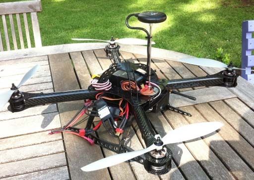
YS-S4 Multi-rotor Autopilot User Manual V1.4

Table of Contents

Table of Contents ....................................................................................................................................................... 2
1. Warning and Disclaimer ......................................................................................................................................... 3
2. In‐the‐Box .............................................................................................................................................................. 4
3. Functions................................................................................................................................................................ 5
4. Installation ............................................................................................................................................................. 6
5. Connections ........................................................................................................................................................... 7
5.1 Assembly .............................................................................................................................................................. 7
5.2 How to connect the modules ............................................................................................................................... 8
6. Configurations Before Flying .................................................................................................................................. 9
6.1 Install Phone GCS ................................................................................................................................................. 9
6.2 Tx Setup.............................................................................................................................................................. 10
6.3 Parameter Setup ................................................................................................................................................ 12
6.3.1 PC Parameter Adjustment ............................................................................................................................... 12
6.3.2 Phone Parameter Adjustment ......................................................................................................................... 14
6.4 Tx Calibration ..................................................................................................................................................... 14
6.4.1 Transmitter channel calibration by PC............................................................................................................. 14
6.4.2 Tx Calibration by Phone .................................................................................................................................. 16
6.5 Fail/Safe Checking .............................................................................................................................................. 17
7. Adjustment Outdoors ........................................................................................................................................... 18
7.1 GPS/Compass Calibration................................................................................................................................... 18
7.1.1 Compass alignment by without Smartphone .................................................................................................. 19
7.1.2 Compass alignment using Smartphone ........................................................................................................... 19
7.2 Motor Arming .................................................................................................................................................... 21
7.3 Motor Mixer Checking........................................................................................................................................ 22
8. Tasks ..................................................................................................................................................................... 23
8.1 Servo Gimbal ...................................................................................................................................................... 23
9. Firmware Upgrade ............................................................................................................................................... 24
Appendix .................................................................................................................................................................. 27
LED Indicator Meanings ........................................................................................................................................... 27
Flight Mode Description ........................................................................................................................................... 28

                                                                                       2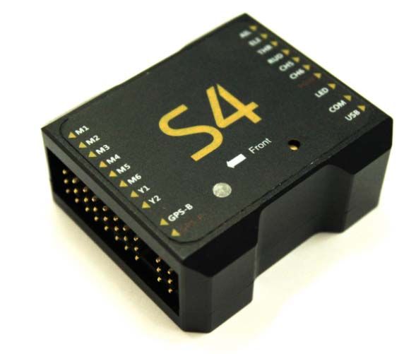
YS-S4 Multi-rotor Autopilot User Manual V1.4
1. Warning and Disclaimer
Thank you for purchasing this ZERO UAV product. The product is an advanced and specifically dedicated control
item. Any misuse may result in damage to property, injury or even death. The user must conform to the law and
use the equipment responsibly. This product is not suitable for people under the age of 18. Please read this
disclaimer carefully before using the product, or visit the YS‐S4 web page at http://www.zerouav.com to refer to
relevant updates or information.
Warning
Please keep the product out of reach of children.
Make sure the aircraft is kept away from people and dangers such as buildings roads and property.
We suggest you fly your aircraft at specially designated areas.
Please do NOT fly this product when affected by drunkenness, tiredness, drugs, dizziness fatigue,
nausea or any other condition that might impair your ability to control the aircraft.
Please strictly follow the user manual when operating the device.
Please make sure all components of the device are connected and work well, otherwise your unit may
be damaged, destroyed or even buried!
Please power off and remove propellers before making any adjustments to the unit such as calibrating,
upgrading firmware or changing parameters. There is an ever present danger of the propellers starting
unexpectedly and causing injury.
Please do NOT fly in unfavorable conditions.
Please do NOT open or modify the autopilot, there are no user serviceable parts inside.
Disclaimer
a. Zero UAV (Beijing) Intelligence Technology Co. Ltd. assumes no liability for damage(s) or injuries
incurred directly or indirectly from the use of this product.
b. The user is responsible for abiding with the law and not behaving contrary to public order or public
safety by using this product.
c. ZERO TECH accepts no liability for damage(s) or injuries directly or indirectly from the use of this
product in the following conditions:
1) Damage(s) or injuries incurred when users are drunk, taking drugs, drug anesthesia, dizziness, fatigue, nausea
and any other conditions no matter physically or mentally that could impair their ability.
2) Damage(s) or injuries caused by intentional operation or accident.
3) Any mental damage compensation caused by intentional operation or accident.
4) Failure to follow the guidance of the manual to assemble or operate.
5) Malfunctions caused by refit or replacement with non‐ZERO TECH accessories and parts.
6) Damage(s) or injuries caused by using third party products or fake ZERO TECH products.
7) Damage(s) or injuries caused by misuse or poor judgment.
8) Damage(s) or injuries caused by mechanical failure due to wear and tear.
9) Damage(s) or injuries caused by continued flying after low voltage protection alarm is triggered.
10) Damage(s) or injuries caused by knowingly flying the aircraft in an abnormal condition (such as water, oil, soil,
sand and other unknown material ingression into the aircraft or if the assembly is not completed, the main
3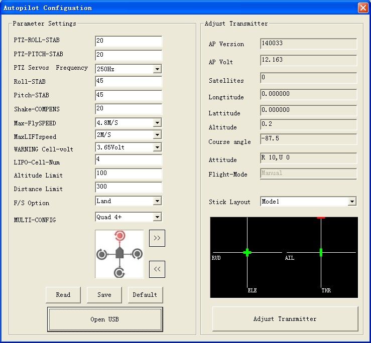
YS-S4 Multi-rotor Autopilot User Manual V1.4

     components have obvious faults, obvious defects or missing accessories).
11) Damage(s) or injuries caused by flying in the following situations: Using the aircraft in a magnetic interference
     area, radio interference area or government regulated no‐fly zones, in bad light, when the pilot has blocked,
     fuzzy or poor eyesight or in any other conditions not suitable for operating.
12) Damage(s) or injuries caused by using in bad weather, including rain, wind (more than a moderate breeze), snow,
     hail, lightning, tornado, hurricane etc.
13) Damage(s) or injuries caused when the aircraft is in the following situations: collision, fire, explosion, flood,
     tsunami, subsidence, ice trapped, avalanche, debris flow, landslide, earthquake, etc.
14) Damage(s) or injuries caused by infringement such as litigation caused by any data, audio or video material
     recorded by the use of aircraft.
15) Damage(s) or injuries caused by the misuse of the battery, protection circuit, RC model and battery chargers.
16) Other losses that are not covered by the scope of ZERO TECH liability.

           2. In the Box
                                                                    ■ Hardware □ Software
       ■ Main controller x1
       The MC (Main Controller) with its integral Inertial Measurement Unit (IMU) combines and communicates
       with the other modules and external electronic devices to carry out its function as a complete autopilot
       system.

       ■GPS+COMPASS         x1
       The GPS/Compass module is for sensing the orientation of the aircraft by reading its
       position and direction

       ■LED x1
       The LED indicates the current flight status of the craft. . The light shows information such as flight mode,
       number of satellites in view and battery used.

                                                               4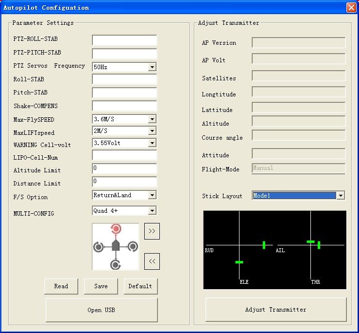
YS-S4 Multi-rotor Autopilot User Manual V1.4

       ■ Power Module x1
       Supplies regulated power for the autopilot

       ■GPS Bracket x1
       The GPS+COMPASS is sensitive to magnetic interference. This bracket is used to mount the GPS module
       where necessary and to keep it far away from EMI sources.
       ■Warranty Information Card X1
       This provides Product Serial No., Purchase Date. Please fill out the relevant information and return to Zero
       UAV to register your product warranty.
       Software available on website for download:
       □ GCS So ware for Android System
       □ GS Software for PC Windows XP/7/SP3 system
       □ Firmware Upgrade So ware on PC.
       □ Firmware updating assistant.

          3. Functions
1)   Supported multirotor layouts:
             Quad X4, Quad +4, Hexa X6, Hexa +6.
2)   Four working modes:
                             i.     Manual flight stabilisation
                            ii.     Manual altitude hold
                            iii.    Auto hover
                            iv.     Return home and land.
3)   Standard safety features when the aircraft loses control :
      Fail safe: auto return‐home and auto‐landing, failsafe: land, failsafe: auto‐hover
4)        The LED indicates the autopilot’s current status. (GPS lock, low voltage alert,
            Attitude error, etc.)
5)   Control method: RC Transmitter
6)   Parameter adjustment by Android Phone, Tablet or PC
7)        Firmware upgrade support: Upgrade firmware via USB cable to COM port.
8)   Receiver support: All PPM receivers
9)   Gimbal support: Servo gimbal

                                                                  5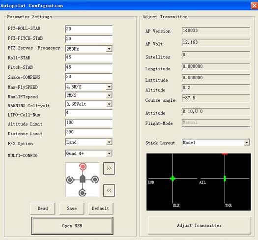
YS-S4 Multi-rotor Autopilot User Manual V1.4

          4. Installation

     4.1 YS‐S4 Module Installation

1)        The YS‐S4 Module should be placed level on the main body of the aircraft.
2)        For best results install at the Center of Gravity (CoG) of the aircraft.
3)        The “ Front Arrow” MUST point towards the head of the aircraft:

                     Towards aircraft nose

     IMPORTANT:
     The YS‐S4 will adapt to most aircraft types without inner dampening. It may not adapt satisfactorily to larger
     aircraft in which case the YS‐S4 should be mounted on the optional dampening structure shown below and
     available from ZeroUAV.

                                            YS‐S4 dampening structure

     4.2 GPS Module Installation

     1)   Ensure that the sticker faces up and the arrow points towards the head of the aircraft. Otherwise the aircraft
          may fly in circles when in auto‐hover mode.

     2)   The GPS module should be installed on a level GPS stand, mounted higher than the electrical components on
          the aircraft. This ensures minimal magnetic field effect from the other on‐board components, such as power
          cables, transmitters, motors, ESCs and camera.

                                                                6
                                                                    Arrow towards
                                                                    aircraft head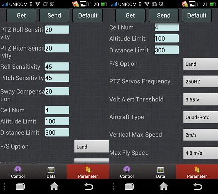
YS-S4 Multi-rotor Autopilot User Manual V1.4

           5. Connections

     5.1 Assembly

     IMPORTANT
a.         Ensure the original factory supplied power module is used. The manufacturer holds no responsibility if the
     S4 is burnt out by using any other power module.

b.         The Power supply module and the WI‐FI module must connect to a 3S‐6S LIPO battery. The voltage range
     would therefore be 10.8V‐25.5V. Normally this would be your main flight battery.

c.         The RC receiver (PPM supported) is powered directly from the MC. DO NOT power the receiver with any
     additional module or the YS‐S4 unit may be burnt out.

d.         Motors and ESCs (Especially when several ESCs are together), can cause serious magnetic interference so
     the GPS module must be as far away from these as possible. A non‐ferric bracket must be used with the arrow on
     the GPS facing forward. Also the battery connection carries a high current and may result in a strong magnetic
     field. Keep the battery wires as far away as possible from the GPS module otherwise your aircraft may fly in
     circles!

e.         If using a servo gimbal, make sure the SERVOs are powered separately.

f.         WHITE core wire is always the signal line, the RED core wire is positive; the BLACK core wire is ground (0v).
                                                              7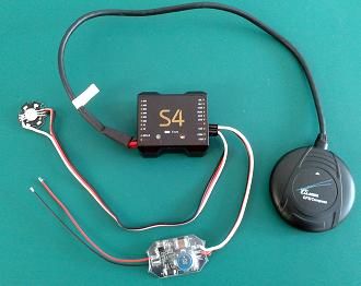
YS-S4 Multi-rotor Autopilot User Manual V1.4
g. Only the USB interface can be used for Parameter Setting and Firmware Upgrade. The COM port is also an
interface to connect to a WI‐FI module.
h. The YS‐S4 DOES NOT support ESC calibration The ESCs should be calibrated independently referring to the
manufacturer supplied ESC manual. It is a good idea to disable the ESC low‐voltage cut out. With most ESCs all
you need do is configure them to NiMH.
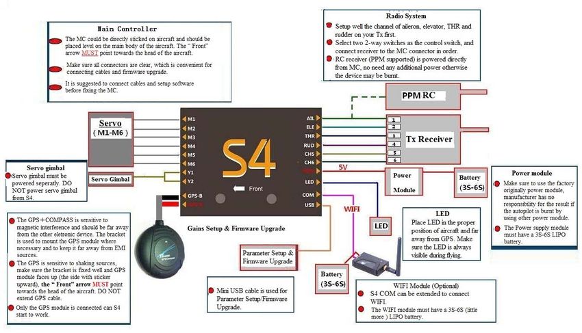
5.2 How to Connect the Modules
1) Connect the power supply module
As shown below, one 3‐core cable is used to connect the S4 to the power unit, the WHITE‐core is up, the
RED‐core is in the middle and the BLACK‐core is below.
The RED and BLACK bare wires should to be soldered to the Positive and Negative pole of the battery pack
connector (3S‐6S Lipo).
2) Connect the LED module
The LED module should be connected to the LED interface of the S4 main controller as shown.
3) Connect the GPS module
The GPS module has red and black ends; the RED end is connected to the S4 GPS‐R interface, and the black end to
the GPS‐B interface. The side of the slot faces up.
4) Connect the receiver
8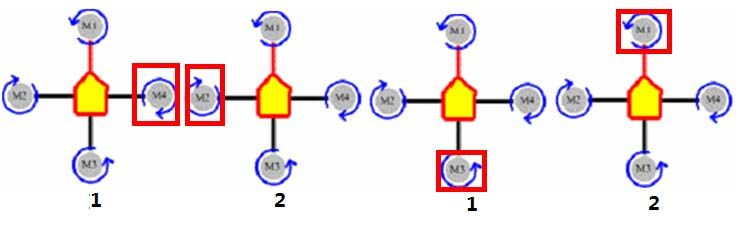
YS-S4 Multi-rotor Autopilot User Manual V1.4

   The receiver should be connected as follows: the WHITE wire (signal) is up, the RED wire (positive) is in the
   middle, and the BLACK wire (ground) is at the bottom. The ESC wires should be connected in the same way but
   NB: If your ESCs have a BEC (supply voltage via a battery equivalence circuit) then you must remove the red wire
   from each. If you are not sure about the BEC, remove the red wire anyway!

   5) Connect the WI‐FI Module (extended connection)
   The WI‐FI data cable is a 3‐core cable, connect the end which has the lock to the WI‐FI module and connect the
   other end to the COM interface on the YS‐S4 (white wire is up, red is in the middle, black is below). The WI‐FI
   module should be powered separately; power supply range is 3s‐6s Lipo.

6. Configuration before Flying

   6.1 Install Phone Ground Control Software (GCS)

         To use the Phone GCS, you must purchase the optional WI‐FI module. Download the “Phone‐GCS

   Software‐YS S4V2” from our official website

   http://www.zerouav.com/en/service/Download/Software/

   The App must be installed to the Mobile‐phone memory card. It can be installed automatically by selecting
   INSTALL on the APK file once in the file manager.

                                                            9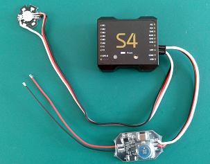
YS-S4 Multi-rotor Autopilot User Manual V1.4

                                                    S4V2‐GCS

Start the GCS; you will see the serial number and firmware version for the autopilot on the interface once the
data has connected.

After connecting your WI‐FI to the GCS successfully, you can also see the real‐time updated data on the "Data"
Page.

   6.2 TX Setup

        1)   Select fixed wing model on your transmitter. Remove any channel mixing.
        2)   FUTABA Radio: All channels should be Normal (not reversed).
        3)   JR, JTm, Spektrum and WFLY Radios: Reverse all channels.

Step 1: Select Two Switches
Ensure your radio has two sets of two‐way switches. Programme CH5 and CH6 to these switches to control the
flight modes:

                                                        10
YS-S4 Multi-rotor Autopilot User Manual V1.4
CH5 Position1—Manual Stabilization Mode
CH6 Position1—Neutral
CH5 Position2—Auto Mode
CH6 Position2 — Return and Land
Adjust your two‐way switch end points to control the flight modes:
CH5 Position CH6 Position GPS Status Working Mode
Position 1 Position 1 X Manual Stabilization
Position 2 Position 1 GPS No Lock Manual Altitude Hold
GPS Lock(above 5 satellites) Auto Hover
X Position 2 GPS Lock(above 5 satellites) Return and Land
IMPORTANT:
Return and Land mode always takes priority. In any mode the autopilot will perform the Return and Land
operation if CH6 is switched to position2.
Step 2 Fail‐Safe Setup (F/S)
There are 2 ways of setting up F/S: default mode and optional mode
1) Default F/S mode
Check with your Radio manual on how to set the Receiver failsafe. Ensure that when you turn OFF your radio,
your failsafe settings are as follows:
CH5 set to position 2
CH6 set to position 2
THR set 50% (mid‐point)
Default F/S only has Return and Land mode which means the YS‐S4 will command the aircraft to Return and Land
automatically if the communication between the TX and the autopilot is disconnected.
2) Optional F/S Setup
IMPORTANT
1) This only applies to FUTABA transmitters.
2) “Optional F/S” is not recommended for beginners because the setting procedure is very complicated.
Ensure that when you turn OFF your radio, your failsafe settings are as follows:
CH5 is set to position 2
CH6 is set to 50% (mid‐point)
11YS-S4 Multi-rotor Autopilot User Manual V1.4
THR is set to 50% (mid‐point)
Check with your Radio manual on how to set the Receiver failsafe.
Here you can choose any of the following F/S modes: Auto RTH and Land; Auto Land and Auto Hover. Now the
YS‐S4 autopilot will control the aircraft according the pre‐programmed F/S mode if the aircraft loses the TX signal.
(set this up on the PC software under “Fail Safe” options)
Please refer to this video for help setting up your TX:
http://www.tudou.com/programs/view/e1ai526Mbt4/
6.3 Parameter Setup
YS‐S4 Parameter setting can be achieved using a mobile phone or tablet (must be connected to WI‐FI) or by using
a PC to adjust the parameters.
6.3.1 PC Parameter Adjustment
Please download the special “PC‐Parameter Setup Software” from the Zero website before parameter
configuration.
IMPORTANT
1) “PC‐Parameter Setup Software” is also the firmware upgrade tool;
2) S4 will choose different working modes if the sequence used in powering‐on is different:
If you power the S4 first and then connect the USB cable you will be in “Parameter Setup” Mode.
If you connect the USB cable first and then power on the S4 then you are in “Firmware Upgrade” Mode.
PLEASE NOTE THE FOLLOWING WHEN SETTING UP AND INSTALLING THE S4:
When the craft is on the ground, power the TX first and then power the S4. Please MAKE SURE propellers are
removed before connecting the battery to prevent injury from the motors starting unexpectedly.
a. Power the YS‐S4 first and then 2 seconds later connect the YS‐S4 module to your PC via the USB
interface. MAKE SURE the THR stick is at the bottom. Connect the mini USB cable.
b. Select and open software “S4‐GCS‐USB.exe”, press “Open USB” and press the ‘Read’ button (If this
fails try several times) to download your YS‐S4 module current aircraft configuration.
c. Press ‘Save’ button (If this fails try several times) to upload the newest parameters to the YS‐S4 if the
parameters have been changed.
d. To restore the default parameters, push THR stick to bottom and press ‘Default’ button.
e. The S4 V2 default parameters are shown below:
12YS-S4 Multi-rotor Autopilot User Manual V1.4
Roll sensitivity and Pitch sensitivity would affect the degree of command response in flight (Default value is 45,
range 0‐255), Motion Compensation can increase stability but would decrease the sensitivity (Default value is 20,
range0‐255).
Roll/Pitch sensitivity is used to adjust the compensation angle of the PTZ
data for your Gimbal. Your can compensate high or low for aircraft
movement within a range from -127 to 127 (Note: You can enter a negative
value to reverse the direction of compensation).
Enter this to match the frequency of your gimbal servos. 50Hz, 250Hz,
333Hz and 400Hz servos are supported.
Set up the maximum flight speed.
Set up the Maximum rate of climb and descent.
Enter the voltage per cell required to activate a low voltage alert, for a
Lipo battery this would be normally be 3.65v。
The autopilot can calculate the low voltage alert according to the number of
cells entered. If your phone vibrates once every 2 seconds it is a reminder
that the power is getting low. When it vibrates continuously it means the
power is getting very low and you should land at once.
13YS-S4 Multi-rotor Autopilot User Manual V1.4
The maximum height and distance allowed can be specified. The
maximum is 1500 meters, min 10 meters.
Set up Fail/Safe mode(Auto RTH and Land, Auto Land and Auto Hover are the
options)
Enter your aircraft type.
6.3.2 Phone Parameter Adjustment
Press the “Parameter” option on the GCS when the WI‐FI module is connected and data is being communicated.
To get the current parameters of the aircraft, click the Get button to get the current parameters (Click several
times if it fails).
After changing any parameter settings away from the current settings you must click the Save button (click several
times if it fails), and the revised parameters to the autopilot will be saved.
6.4 TX Calibration
The remote calibration of the YS‐S4 can be achieved in two ways: mobile phone (must be connected to the WI‐FI)
or PC calibration.
6.4.1 Transmitter channel calibration by PC
Step 1: Select the correct stick layout
14YS-S4 Multi-rotor Autopilot User Manual V1.4
In the PC GCS select the "Stick Layout" drop‐down menu. The “Hand Mode” is your transmitter mode (Mode 1,
Mode 2, Mode 3 etc.)
Select the mode according to your preference and the stick layout of your TX.
Step2: Calibrate the sticks
The ‘Adjust Transmitter’ window will appear on the PC GCS. Click ‘OK’ and move your transmitter stick within 5
Seconds to their maximum positions as shown in the diagram:
Step 3: Check that the stick direction as depicted on the screen matches the actual direction of movement of
your sticks.
15YS-S4 Multi-rotor Autopilot User Manual V1.4
Check that the display of each stick shows that TX is calibrated well. This screen displays the position of the sticks.
On the left is the Rudder and Elevator (Mode 1 depicted). On the right is the aileron and THR stick (Mode 1
depicted).
When both sticks are in the middle position they are shown as GREEN, any other position shows RED except for
when the throttle stick is at the bottom when it shows as YELLOW. When the throttle is in hover position
(normally close to the middle position) it shows GREEN, other flying status shows RED.
6.4.2 TX Calibration by Phone
Step 1 Select the correct stick layout (Mode 1, Mode 2, Mode 3 etc.)
1) Click the menu button on your phone then select "Set” (see below)
2) In the "Set" box which opens select the "Hand Mode" drop‐down menu. The “Hand Mode” is your
transmitter mode (Mode 1, Mode 2, Mode 3 etc.)
16YS-S4 Multi-rotor Autopilot User Manual V1.4
3) Select your own operation style in the hand mode menu. The illustration shows “Japan Hand” which is
Mode 1.
Step 2 Calibrate the sticks
Click the button “Adjust Transmitter” on GCS “Data” and click "OK" in the dialog box. Move both sticks to their
end points in a circular motion within 5 Seconds. The autopilot will store the maximum and minimum end points
and also the mid points of both sticks.
6.5 Fail/Safe Checking
Step 1 Check that Flight Modes change on TX command:
1) Check Flight Modes via the Configuration software ‘Flight Mode’:
Assuming your GPS module is connected; check whether switching between all working modes is working
normally.
For example: Place CH5 at position1 and CH6 at position1, the PC GCS "data" page should show your TX status as
"Manual", Change CH5 to position 2 for Auto Hover and so on. If flight mode does not change when you toggle
the switches please check your hardware connections or RC Transmitter setup.
Step 2: Fail Safe (F/S) Checking
1) How to check default F/S
SWITCH OFF the RC Transmitter whilst the autopilot is still powered on; the ‘Flight‐Mode’ should switch to
display "Return and Land", the throttle stick indicator should be in the middle and displayed in GREEN. If it does
not, please setup the fail‐safe (F/S) again. It is strongly recommended to use the default F/S.
2) How to check optional F/S
17YS-S4 Multi-rotor Autopilot User Manual V1.4
SWITCH OFF the RC Transmitter whilst the autopilot is still powered on, the ‘Flight Mode’ should switch to display
"Return and Land", “Land” or “Auto hover” ( these options are the chosen F/S settings from your PC GCS ) the
throttle stick indicator should be in the middle and displayed in GREEN. If not, please setup the fail‐safe (F/S)
again.
7. Adjustment Outdoors
7.1 GPS/Compass Calibration
When using the S4 V2 autopilot for the first time, the GPS/COMPASS must be calibrated before arming the
motors.
IMPORTANT:
(1)Compass calibration does not need to be done every time you fly but should be done when components are
moved or if the aircraft flies in unexpected ways, like in circles, for example.
(2) ALWAYS carry out this calibration outdoors, far away from metallic objects (cars, radio towers, power lines
etc.).
There are two ways to calibrate the compass: by Smartphone (with WI‐FI module) or by PC. There are 3 steps to
follow:
1. Level calibration
2. Vertical calibration
3. Save GPS/COMPASS data.
18YS-S4 Multi-rotor Autopilot User Manual V1.4
7.1.1 Compass alignment without Smartphone.
Step 1
Move CH5 and CH6 on the transmitter to Position1 and make sure Channel 5 & 6 switches are in position 1
( Manual Mode). Level your multicopter. Flip CH5 switch three times quickly between Position 1 and Position
2( 1 > 2 > 1 > 2 > 1 > 2 > 1) and the LED turns green. You have entered Horizontal Calibration.
Step 2
Rotate the multicopter counter clockwise( or clockwise) three times. ENSURE that the GREEN LED remains ON
during this procedure. If it turns OFF, it means the aircraft is not horizontal. Adjust the position until the GREEN
LED is back ON and continue with the rotation and put the multicopter level again.
Step 3
Flip CH5 switch three times(1 > 2 > 1 > 2 > 1 > 2 > 1) and the LED turns off. You have entered Vertical Calibration.
Hold the multicopter nose down and the LED turns green.
Rotate the multicopter 3 times counter clockwise as shown below, always keeping the aircraft nose down. Ensure
the GREEN LED remains ON during the turn. If the LED turns OFF, adjust the attitude of the multicopter until the
GREEN LED is back ON and continue with the rotation and put the multicopter level again when finished the
rotation. The LED turns off.
Step 4
Flip CH5 switch three times (1 > 2 > 1 > 2 >1 >2 >1)quickly and the LED turns green. Wait until the LED turns off.
That indicates the compass calibration is done.
7.1.2 Compass alignment using Smartphone
Step 1
Click the “Magnetic Compass” button on the Phone GCS "Data" Page:
19YS-S4 Multi-rotor Autopilot User Manual V1.4
Step 2
Select "Horizontal Alignment" in the dialog box, and then click "OK" button to start level calibration. If you don't
want to keep calibrating select "Cancel" and confirm “OK”.
Step 3
Level your aircraft and carefully turn around horizontally three times. ENSURE that the GREEN LED light remains
ON during this procedure. If it turns OFF, that means the aircraft is not horizontal. Adjust the position until the
GREEN LED is back ON and continue with the rotation.
Step 4
Select "Vertical Alignment" in the dialog box, and click "OK" button to start the vertical calibration. If you don't
want to keep on calibrating select "Cancel" and confirm “OK”.
Step 5
Carefully rotate the aircraft 3 times as shown below, always keeping the aircraft nose down. Ensure the GREEN
LED remains ON throughout the turn. If the LED turns OFF, adjust position until the GREEN LED is back ON and
continue with the rotation
20YS-S4 Multi-rotor Autopilot User Manual V1.4
Step 6
Click "Save Alignment" the dialog box, and click "OK".
Step 7
Now the GCS software will automatically switch to the “Control” interface screen and after a period of calculation
will display two circles, a BLUE one and a RED one. The YS‐S4 will enter the magnetic recording and the LED will
now flash GREEN. Calibration will be completed seconds later when the GREEN flash turns OFF.
Excellent OK Failure
The circles are shown in the picture. If the circles are more or less round, this means the
Calibration has been successful. If not, then you need to do the calibration again.
IMPORTANT:
There is no need to do the Compass calibration every time you fly or upgrade the firmware once your flight
controller component installation and compass calibration has been completed, but it should be done when
components are changed or if the GPS is removed.
7.2 Motor Arming
For safety reasons, the S4 locks the motors on landing. They can only be re‐armed to allow them to rotate and
work after carrying out the “arming” procedure.
IMPORTANT:
Motor arming will fail if the GPS module is not connected.
Enable the “Combined‐Stick‐Command” (CSC) for motor arming as shown below:
To arm, push the left‐hand stick to the far left and extreme bottom, the right stick to the far right and to the
bottom.
This is for Japanese and American convention (mode 1 and mode 2) and is called /\ type. For Chinese and
European operation (Mode 3 and Mode 4), you need to apply the \/ type to arm the motors.
21YS-S4 Multi-rotor Autopilot User Manual V1.4
After the CSC operation, push the THR stick slightly up. The motors should begin to turn. You need to apply more
throttle to take off normally.
7.3 Motor Mixer Checking
Before take‐off, you still need to check your motor mix control.
First let’s take the quadcopter + type as an example to simply describe how to check motor mix control (Please
refer to the illustration for other aircraft configurations). You need to arm the motors and check what happens
when you advance the throttle stick, if the four motors rotate at the same speed this means the motor balance is
good.
1. To check the aileron channel, slightly push the aileron stick to the left, motor M4 should rotate immediately
(see 1 on the illustration below), the other three motors should keep still. Push the aileron stick to the right
slightly, motor M2 should rotate immediately (see 2 on the illustration below), the other three motors should
keep still.
2. Check the elevator channel. According to the aircraft symmetry it should be similar to checking the aileron
channel. Push the elevator stick up slightly, motor M3 should start to rotate (see 3 on the illustration below) now
slightly pull the elevator stick down and motor M1 should start to rotate immediately (see 4 on the illustration
below).
Quadcopter X type
22YS-S4 Multi-rotor Autopilot User Manual V1.4
Hexacopter+ type:
Hexacopter X type:
8. Tasks
8.1 Servo Gimbal
Powering the servos when using a gimbal with the S4:
Servo Battery
GND
VCC Gimbal Servo
Signal
Y1/Y2
Connector
Connect Y1 to the gimbal roll servo and Y2 to the gimbal pitch servo. Enter “Roll Sensitivity” and “Pitch
Sensitivity” in the Parameter Section of the GCS to adjust the correction angle and direction of your gimbal.
Gimbal Sensitivity ranges from ‐127 to 127. A negative number reverses the direction of travel and the size of the
number affects the amount of correction.
23YS-S4 Multi-rotor Autopilot User Manual V1.4
You will need a TX with at least 7 channels to use the Gimbal function. Use channel 7 on your transmitter for
gimbal control and assign it to a knob switch, Channel 7 will now adjust your gimbal pitch location and will
continue to stabilize the camera at all angles of pitch. The spare channels may be used for other applications.
Normally roll servos will maintain gimbal stabilization in the middle position. If your gimbal tilts to one side it can
be adjusted it by clicking “Enter Setup” in the Setting section (CH5 must in manual and the throttle set to
minimum) Now the CH7 knob can be used for controlling gimbal roll. The gimbal roll’s balance position may be
fixed and saved by clicking “Quit Setup”. Now CH7 will revert to controlling gimbal pitch.
9. Firmware Upgrade
IMPORTANT:
For safety, please remove all the propellers before upgrading firmware.
You may download the latest firmware and assistant tool from the ZeroUAV website before upgrading the
firmware.
(1) Connect the YS‐S4 to the computer with a Mini USB cable. Power the S4 and put bring the throttle stick to the
bottom.
(2) Open the S4 Setup Software “ S4‐GCS‐USB.exe”, Click “Open USB” button in the “YS‐S4 firmware upgrade”
window.
24YS-S4 Multi-rotor Autopilot User Manual V1.4
3) Click “OK”
4) Click “Select Firmware” button
25YS-S4 Multi-rotor Autopilot User Manual V1.4
5) Click “Open” button, select upgrade procedure file“s4v2‐BiaoZhun‐20140115‐v021.bin”
6) The program will auto‐upgrade when the upgrade procedure is selected.
7) Power‐off the autopilot when it says “upgrade successful”. Quit the firmware upgrade software and power
off the autopilot.
26YS-S4 Multi-rotor Autopilot User Manual V1.4
Appendix
LED Indicator Interpretation:
The working status of the S4 is basically indicated by the GREEN + RED LEDs, see below:
Flight Status LED status Description
Manual(GPS NOT LOCKED) 1 second GREEN and 1 second RED
Manual(GPS LOCKED) 2 seconds Green once per loop
Manual altitude‐hold 2 seconds GREEN and 1 second RED
Auto‐hover 3 seconds GREEN
First stage low voltage alert 2 seconds RED
Final stage urgent low voltage alert 3 seconds RED
Return and Land Continuous RED flashing
Magnetic compass calibration Continuous GREEN flashing
IMU Error Continuous YELLOW flashing
The autopilot can calculate the low voltage alert according to the Cell Number filled in by the user. “Final stage
low voltage alert Number”= (Voltage per cell ‐ 0.05v) * Cell Number
E.g. voltage per cell 3.7 ‐0.05v =3.65 multiplied by cell number = total voltage (14.6v for 4 cells)
When the final low voltage alert is indicated, the craft will land (You can adjust the landing position during
landing but make sure you DO NOT push the THR stick during this operation.)
27YS-S4 Multi-rotor Autopilot User Manual V1.4
Flight Mode Description
IMPORTANT
a. Make sure the TX is on first and the throttle stick is at the bottom.
b. DO NOT push the THR stick to the bottom during flying.
c. DO NOT switch to auto‐fly mode until the craft is stable in manual stabilization mode.
d. Switch to manual stabilization mode if craft meets an emergency situation in auto‐fly mode.
(1) Phone/ Tablet Control
(1) Phone Remote Control Mode
During flight, when the transmitter is switched to “Auto‐hover” in “GPS mode”, the aircraft will enter
auto‐hover mode. Now you can activate control of your aircraft via your cellphone by pressing “Enable Control” in
the “Control” screen of your GCS.
NB: When in phone remote control mode, your transmitter control will not work.
28YS-S4 Multi-rotor Autopilot User Manual V1.4
How to control your multi‐rotor by phone or tablet?
Enable Control User Interface Operations Aircraft Status
Red: GPS not locked
Circle status ‐
Green: GPS locked.
Position Hold No Operation Position hold
Drag finger over screen: 1.move forward/backward
1. up/down 2.move left/right
Level Flight
2. left/right 3.Move left/right top,
3. left/right top, left/right bottom etc. left/right bottom etc.
Click below the area inside the cross
1.over circle 2.under circle
3. Left of circle 4. right of circle
1、Climb
NB:
Climb – Descend 2、Descend
(1) The distance between circle and click point is
‐ Turn 3、Rotate to left
proportional to flight speed. The further the
4、Rotate to right
distance, the faster the flying speed.
(2) Time pressing control circle is proportional to
Aircraft movement time
IMPORTANT
1) If GPS is not located (eg. indoors), Phone/Tablet remote control function is not available.
2) The WI‐FI module must be connected when using Phone/Tablet remote control mode.
(2) Manual Stabilization Mode
In Manual Stabilization Mode (TX CH5 and CH6 in position1), the aircraft will fly normally and is stabilized in 3
axes.
The aircraft may be controlled by TX, but is also controlled by the stabilization signal of the YS‐S4 autopilot. The
final flying state is determined by a combination of manual control and autopilot control.
YS‐S4 flight is characterized by stable calm flights. Do not fly fast, violent maneuvers with large stick inputs when
using this controller.
(3) Manual Altitude Hold
When GPS is not located (when satellites locked are less than 5) and when CH5 is in position2 and CH6 in
position 1, the S4 will enter manual altitude‐hold mode.
29YS-S4 Multi-rotor Autopilot User Manual V1.4
In this mode, craft will hold the altitude but not hold the position. When the THR stick is in its 50% position
the craft will hover in the current altitude but not at its current position (the craft will drift when the GPS is not
locked), but the craft can still be controlled manually. Left/right is controlled by the AILERON Stick, Up/Down
controlled by the ELEVATOR stick, direction is controlled by the RUDDER stick, and height controlled by THR stick.
If the THR stick is 50%, craft will auto‐hover;
If THR stick is more than 50%, craft will fly upward;
If THR stick is less than 50%, craft will descend.
The Craft can fly to any altitude controlled by THR stick, and fly to any position controlled by the other
sticks.
(4) Auto hover
With GPS located (when satellites locked are more than 5) and CH5 is in position2 and CH6 in position1, the
S4 will enter auto‐hover mode.
In this mode, the aircraft will hold its position and altitude. Your TX sticks should all be in the mid position. When
THR stick is around the mid position the craft will hover in its current position, (The craft does not drift because
GPS has locked) and also may controlled manually.
Left/right is controlled by the AILERON Stick, Up/Down controlled by the ELEVATOR stick, direction is
controlled by the RUDDER stick, and height controlled by THR stick.
If the THR stick is 50%, craft will auto‐hover;
If THR stick is more than 50%, craft will fly upward;
If THR stick is less than 50%, craft will descend.
The Craft can fly to any altitude controlled by THR stick, and fly to any position controlled by the other
sticks.
(5) Return and Land (RTL)
With GPS locked (more than 5 satellites locked) and Motor arming done, the craft will record its home position.
a) Push CH6 to position 2 to enter RTL (return and land) mode. In the Return and Land mode, the craft will return
home and land automatically.
b) After activation, you can only change to Stabilization Mode if you want to take over the flight controls. If you
move from RTL to Auto Hover Mode, the aircraft will continue with the Return and Land process.
c) On arrival at ‘Home’, the YS‐S4 V2 will begin to descend. At this time, the autopilot will allow you to take over AIL
and RUD controls to adjust the landing site, but the THR cannot be controlled. The THR control is fully
autonomous for descent and landing.
d) Altitude: If the craft is beyond 25 meters away from home position and below 20 meters altitude, the YS‐S4 V2
will ascend to 20 meters before initiating RTH when it enters RTL mode. If its height is more than 20 meters, the
YS‐S4 V2 will maintain altitude during RTH. If the distance from home position is more than 20 meters, the YS‐S4
30YS-S4 Multi-rotor Autopilot User Manual V1.4
V2 will maintain its previous altitude during RTH.
e) Safety: Since RTH is fully autonomous and you cannot alter the flight path during RTH, to avoid accidents, it is not
advisable to activate RTH too close to you or spectators. Also note to avoid sudden loss in altitude, the THR stick
should be above its mid‐point when you change the mode back from RTH to Stabilized Mode.
Switch CH6 to position1 from position2 to quit RTL mode.
After landing the motors will stop. Move your THR stick to the bottom, 5 seconds later the motors will lock.
Arm the motors to restart flying.
Support
Website:www.zerouav.com
Telephone:0086‐10‐57250711
31You can also read