GATE 3S Fieldbus unit - Operating and Installation Instructions
←
→
Page content transcription
If your browser does not render page correctly, please read the page content below
GB

                            Fieldbus unit
                            GATE 3S

Operating and
Installation Instructions
Fieldbus unit GATE 3S
Contents
1. Introduction
Functions ......................................1-1
4. Operating instructions
General ............................................. 4-1
Technical data ................................1-3
Start-up ............................................. 4-1
Status views, ‘Gen. 3’ and E-2-WEI ... 4-2
2. Installation Status views, microPOS ................... 4-3
Mechanical installation ..................2-1 Bus diagnostics ................................. 4-4
Electrical installation ......................2-1
Network installation .......................2-2
Line termination ............................2-2
5. Communication
Serial communication interface ......... 5-1
Memory mapping in GATE 3S .......... 5-1
3. Set-up
General .........................................3-1
Panel set-up ..................................3-1
6. Troubleshooting
General ............................................. 6-1
Parameters ....................................3-6
Appendices
Set-up list for GATE 3S .................Appendix 1
Profibus-DP ...................................Appendix 2
Ethernet, Modbus-TCP .................Appendix 3
INTERBUS ....................................Appendix 4
DeviceNet .....................................Appendix 5
Modbus Plus .................................Appendix 6
CANopen ......................................Appendix 7
ControlNet .....................................Appendix 8
Declaration of Conformity ..............Appendix 9Operating and Installation Instructions
Fieldbus unit GATE 3S

1. Introduction
Fieldbus unit GATE 3S is developed to enable integration into fieldbus systems
of instruments and servo units from Nobel Weighing Systems. They connect to
GATE 3S through a serial communication port.
For the fieldbus connection, internal adapters for a number of common fieldbus
types are available. These adapters include dual port memories that can be
written and read from the fieldbus, and also from the slave units connected to
the serial communication port.
Data transmission is performed by groups of bytes at high speed, allowing
connection of several slave units to a fieldbus through one GATE 3S.
GATE 3S has a front panel with four function keys and a display, used for
supervision of status and output signals in the network. The display can
also be used in bus diagnostics to study the actual contents of any part of
the dual port memory.
Configuration of GATE 3S is easily performed, using the display and function
keys to set a few operation parameters for the actual installation.
GATE 3S is quickly snap-mounted on a DIN-rail or screw-mounted on a flat surface.

Functions
Master in a network for measurement or control.
GATE 3S has one serial port for communication by the Modbus RTU protocol and
RS-485/RS-422 on 2-wires or 4-wires. To this serial port, several units for weight or
force measurement, or servo units for position control, can be connected to make up
a network with GATE 3S as master.
GATE 3S constantly sends requests for measurement values and status messages
to all units in the network, and collects the received reply data in the dual port memory
where it can be read by the fieldbus.
Over the fieldbus, commands and setpoint values are entered in the dual port memory,
and are distributed by the serial communication port of GATE 3S to the intended
network unit.
High transmission speed gives very short transfer times in GATE 3S.

 GATE 3S supports the following types of units from Nobel Weighing Systems obel:
• AST 3 from programme name A001A130, TAD 3, and WEI 3 for weight and force
   measurement.
   These instruments are here referred to as ‘Generation 3’.
• E-2-WEI, programme name W107A204, for weight and force measurement.
• microPOS servo units, from programme name M003A300, for position control.

                                                                                      1-1
Operating and Installation Instructions
Slave unit in a fieldbus system.
Connection of GATE 3S to the fieldbus system is done through an internal adapter unit.
Adapters, type AnyBus-S from HMS Industrial Networks (www.hms-networks.com) are
available for several common fieldbus types. Communication parameters for the fieldbus
system must be set from the fieldbus master or by switches at the adapter unit in
GATE 3S. For connection, setting of possible adapter switches, and understanding of
possible indicators, refer to an appendix according to the summary below.
Appendix 2: Profibus-DP (standard)
Appendix 3: Ethernet, Modbus-TCP
Appendix 4: INTERBUS
Appendix 5: DeviceNet
Appendix 6: Modbus Plus
Appendix 7: CANopen
Appendix 8: ControlNet
Supervision.
By normal operation GATE 3S is in ‘Operation’ mode, and the panel display is used
to show operating status, OK ( = 1), WRONG ( = 0), or INACTIVATED ( = *) for all
connected units in the measurement or control network. By the function keys it is
also possible to select display of output and status for just one of the connected
units at a time.
Diagnostics.
The diagnostics function, described in section 4. Operating instructions, can be used
for troubleshooting. It allows reading of input and output data from the internal
GATE 3S memory for any network unit.
Parameter set-up.
GATE 3S operation and network characteristics are controlled by parameters.
All parameter values can be set with GATE 3S in Set-up mode, using the function keys
and the panel display.
Parameter setting is described in section 3. Set-up.
GATE 3S
AST 3 RS-485 Modbus Fieldbus Fieldbus
RTU master.
TAD 3 Local network Fieldbus
master. adapter.
Figure 1. GATE 3S acts as intermediary for information between the fieldbus
master and the units in the weighing or control network.
1-2Fieldbus unit GATE 3S
Technical data
Measurement and control port
Serial communication RS-485 / RS-422 2-wires or 4-wires.
Baud rate max. 460 kbaud.
Protocol Modbus RTU (multidrop).
Units that can be connected:
Generation 3 units AST 3B / P / IS, Progr. name A001A130 or later.
TAD 3. WEI 3.
Fast mapping 6 byte in: control commands (zero, tare, etc.).
6 byte out: weight, weight status.
number of units 1 – 16. *)
total transfer time 4 ms / unit (at 115 kbaud).
General mapping 20 byte in: control (zero, tare, etc.), setpoints,
write to any register.
20 byte out: weight, status info,
read from any register.
number of units 1 – 16. *)
total transfer time 6 ms / unit (at 115 kbaud).
Weight transmitter units E-2-WEI, Progr. name W107A204.
Mapping 20 byte in: control (zero, tare, etc.), setpoints.
20 byte out: weight, status info.
number of units 1 – 16. *)
total transfer time 60 ms / unit (at 9.6 kbaud).
Positioning servo units microPOS, progr. name M003A300 or later.
Mapping 6 byte in: setpoint positions.
6 byte out: feedback positions, in position.
number of units 1 – 16. *)
total transfer time 10 ms / unit (at 115 kbaud).
*) Max. number of units can be lower for some fieldbus types.
The number of units may also be limited by the master capacity.
Transfer in the fieldbus is not included in the above transfer time data. These times
are normally shorter, but depend on the fieldbus configuration and speed.
1-3Operating and Installation Instructions
Fieldbus interface
Anyone of the following fieldbus types can be used:
Profibus-DP (standard).
Ethernet, Modbus-TCP.
INTERBUS.
DeviceNet.
Modbus Plus.
CANopen.
ControlNet.
Power supply
Supply voltage 24 VDC ±20 %.
Consumption 4 W.
Environmental
Temperature
operation -10 to +50 °C.
CE conformity EMC, industrial for process control.
Mechanical data
Dimensions 75 x 100 x 110 mm.
At least 10 mm between adjacent units.
Mounting rail DIN 46 277 or DIN EN 50022 (35 mm).
Dust / moisture IP 20.
Front panel
Display 2 x 16 character LCD display.
Keys 4 keys for control and parameter set-up.
30
110
5
7
35 100
75
Mounting holes, The snap fastener for
60 2 x 4 mm dia. DIN rail can be opened
with a fine screw driver.
85
Figure 2. Mechanical dimensions for GATE 3S.
1-4Fieldbus unit GATE 3S
2. Installation
Mechanical installation
Figure 2.
Each fieldbus unit GATE 3S contains circuit boards for the local network and one
adapter unit for the fieldbus, all built into a protective plastic housing.
GATE 3S can be snap-mounted on a 35 mm wide DIN rail or screw-mounted on
a flat surface.
Leave a gap of at least 10 mm between adjacent units.
Electrical installation
GATE 3S is connected both to a fieldbus and to a local network with slave units like
instruments for weighing / force measurement or servo control units.
All electrical connections to GATE 3S are made through plug-in terminals and/or
connectors. Shielded cables are needed, except for the power supply, and the cables
should be routed so that electromagnetical interference is avoided.
In GATE 3S the local network and the fieldbus are galvanically separated.
Cable connection for power supply and serial communication is shown below.
Fieldbus connection is described in an appendix for each fieldbus type.
Serial communication
Terminals 1 – 5.
A transmission line with RS-485 / RS-422, on 2-wires 4-wires
or 4-wires with common signal ground (COM), is used 1 TXD–
to connect instruments or servo units to the serial port
2 TXD+
at GATE 3S. Shielded cable with twisted pairs should
be used. The cable shield should be connected to 3 RXD–
ground, preferably to a ground terminal on the mounting 4 RXD+
rail. 5 COM.
ON ON
SW2
The transmission line must be terminated at both ends SW1
(see figure 3 on next page).
For GATE 3S, see ‘Line termination’ on next page.
2-wires
For other units, refer to the ‘line termination’ section in 1 TXD–
the installation instructions. 2 TXD+
3 RXD–
Power supply 4 RXD+
5 COM.
Terminals 6 - 8.
ON ON
GATE 3S is powered with 24 VDC, see also Technical SW2
data. Connect terminal 8 to a ground terminal on the SW1
mounting rail. Rail mounted power supplies, intended
for operation of 24 V units, are available from
Nobel Weighing Systems. + 6 +
24 V DC 24V
Please observe power requirements for the units. – 7
8 PE
2-1Operating and Installation Instructions
Network installation
Figure 3.
GATE 3S is an interface unit between a fieldbus system and a network with
instruments or servo units. In the network all slave units are connected in
parallel to a transmission line of 2-wires or 4-wires with common signal ground.
Shielded cable with twisted pairs should be used, and the cable shield should
be connected to a ground terminal at all slave units.
In case of 4-wires connection the transmit terminals (TXD+ and TXD-) in
the network must be connected to the receive terminals (RXD+ and RXD-)
at the serial communication port of GATE 3S.
In case of 2-wires connection both transmit and receive terminals must be
connected to the transmission line at the network units and at GATE 3S,
as indicated on previous page.
In all slave units in the network, ‘baud rate’ and ‘data format’ must be set equal to
the values in GATE 3S. For ‘Generation 3’ units, parameter ‘Serial port mode’
should be set to ‘Modbus auto’ to give automatic setting of these parameters.
For other units, ‘baud rate’ and ‘data format’ must be set manually.
All slave units in the network must have unique addresses. In GATE 3S the slave
addresses are used in parameters ‘Address, slave 1’, 'Address, slave 2’ etc. If any of
these parameters is set to ‘0’, the corresponding slave is taken out of operation.
Arrange for line termination only at the units at the ends of the transmission line,
following the installation instructions for these units.
Line termination
GATE 3S has two switches, SW1 and SW2 close to the serial port terminals, that
control the line termination at the fieldbus unit.
If GATE 3S is not at the end of the line: SW1 = (OFF), SW2 = (OFF).
If GATE 3S is at the end of a 2-wire line: SW1 = (OFF), SW2 = ON.
If GATE 3S is at the end of a 4-wire line: SW1 = ON, SW2 = ON.
4-wires
TXD
RXD
COM. Fieldbus
SW2 = ON
RXD TXD COM. RXD TXD COM. RXD TXD COM. SW1 = ON
TAD 3 AST 3 AST 3 GATE 3S
Addr. 21 Addr. 12 Addr. 11
Slave 4 Slave 2 Slave 1
Line termination. 24 VDC Fieldbus
master.
RXD TXD COM. RXD TXD COM.
TAD 3 AST 3
Addr. 22 Addr. 13
Slave 5 Slave 3
Figure 3. Example of a network with five slave units from ‘Generation 3’, a group of AST 3
units, and a group of TAD 3 units, all connected to GATE 3S by 4-wires transmission.
Note that RXD at the slave units is connected to TXD at GATE 3S, and vice versa.
2-2Fieldbus unit GATE 3S
3. Set-up
General
All operating functions in GATE 3S are controlled by parameters. The parameter
values are permanently saved in the memory, so the settings will not be lost if
the power is turned off.
At delivery the parameters are factory set to default values, giving certain standard
functions at first start-up. These default values are indicated in the parameter
descriptions on page 3-7 to 3-12 and in the set-up list, appendix 1.
At installation, some parameter values must probably be edited to suit
the conditions of the actual installation.
Panel set-up
Normally the panel display is used to supervise the operating status of all slave units in
the local network. But the display and function keys can also be used to view and edit
the parameters that control the GATE 3S operation.
Before front panel editing can be performed, GATE 3S must be switched over
from the normal ‘Operating’ mode to ‘Set-up’ mode.
This is accomplished by pressing the key ↑ for at least 2 seconds.
Figure 4. Before parameter editing can start, GATE 3S must be
switched over to Set-up mode, indicated by this menu.
3-1Operating and Installation Instructions
Operating mode
Start up/Reset
Operating status Profibus-DP
11
for 2 seconds
Enter password: Shown only if
(Wrong) (Correct) 'Security lock' is On.
Set-up mode,
Set-up Menu Menu
GATE 3S set-up Exit set-up
Shown only if
Language Save changes? any changes
English No Esc. Yes have been done.
Display contrast
4
Security lock
Off
Password
Shown only if 'Security lock' is See previous column.
set to 'On'. ****
GATE 3S mode IP-address (1)
Generation 3 6b 192.168
Shown only if 'Gate 3S mode' is Weight format IP-address (2)
set to 'Generation 3 20b' or
'Generation 3 6b'. Integer 000.001
Not shown if 'Gate 3S mode' is Number of slaves Subnet mask (1)
set to 'Slave'. 2 255.255
Not shown if 'Gate 3S mode' is Address,slave 1 Subnet mask (2)
set to 'Slave'. 1 255.000
Not shown if 'Gate 3S mode' is Address,slave 2 Gateway addr.(1)
set to 'Slave'. 7 000.000
Not shown if 'Gate 3S mode' is Baudrate Gateway addr.(2)
set to 'Slave'. 115200 000.000
Not shown if 'Gate 3S mode' is Data format GATE 3S address Shown only if 'Gate 3S mode'
set to 'Slave'. 8-none-1 1 is set to 'Slave'.
See next column.
Figure 5. Parameter values for GATE 3S can be viewed,
and edited by the front panel keys.
3-2Fieldbus unit GATE 3S
Start set-up
Figure 5.
Switching GATE 3S from Operating mode to Set-up mode is performed by pressing the
key ↑ for 2 seconds.
In Set-up mode the display shows: ‘Menu GATE 3S set-up’, possibly after entry of
correct code in the ‘Enter password’ menu.
As Set-up mode starts, the panel keys get the following functions:
–/+ Change main menu.
↑ No function.
↵ Go to parameter viewing/sub menu.
Only two main menus are available: ‘GATE 3S set-up’ and ’Exit set-up’.
To edit a parameter value, parameter viewing must be used to find the parameter.
Parameter viewing
Figure 5.
Press ↵ as ‘Menu GATE 3S set-up’ is displayed.
The name and actual value of the first parameter, ‘Language’, will be displayed. Now it
is possible to step through the parameter menus, using the panel keys
+ and – . Note that the display of some parameters depends on the setting of other
parameters.
Panel key functions during parameter viewing:
– View previous parameter.
+ View next parameter.
↑ Cancel the parameter viewing, go to ‘Menu Exit set-up’
↵ Start editing the value of the displayed parameter.
3-3Operating and Installation Instructions
Parameter editing
As a certain parameter has been found by the parameter viewing, described on
previous page, editing of the parameter value can be started by pressing key ↵ .
A cursor appears at the first character of the parameter value, indicating that
editing can be performed.
The parameter can have a ‘numerical value’ or a ‘choice value’:
A ‘numerical value’ is made up of digits that can be edited individually.
A ‘choice value’ is one value from a list of alternative values for the parameter.
Panel key functions during parameter editing:
– Decrease the digit at the cursor, or
Go to the previous alternative.
+ Increase the digit at the cursor, or
Go to next alternative.
↑ Cancel parameter editing.
(The parameter will be shown with its previous value, without cursor).
↵ Brief: Accept the digit value at the cursor and
move the cursor one step to the right.
2 seconds: Accept the displayed parameter value.
(The parameter will be shown with its new value, without cursor).
After the parameter value is accepted, GATE 3S returns to ‘parameter viewing’ and
another parameter can be selected for editing.
Exit ‘Set-up’
Figure 5.
As the parameter editing is finished, the Set-up mode must be cancelled and
the new parameter values saved in the permanent memory. This is performed in ‘Menu
‘Exit set-up’ and its sub-menu ‘Save changes?’.
Go to ‘Menu Exit set-up’, by pressing ↑ as any parameter is displayed without a
cursor, or as ‘Menu GATE 3S set-up’ is displayed.
Exit the Set-up mode by pressing ↵ as ‘Menu Exit set-up’ is displayed.
If no parameter values have been edited, this finishes Set-up mode and
GATE 3S switches over to Operating mode.
If any parameter value has been edited, sub menu ‘Save changes? No Esc. Yes’
is displayed and answers can be given by the panel keys:
↑ = Esc. Set-up mode is not finished. All edited parameters keep their
edited values.
In this case GATE 3S stays in Set-up mode.
– = No. All parameters resume the values they had before the parameter
editing was started.
↵ = Yes. All edited parameter values are saved in the permanent memory.
In these two cases GATE 3S switches over to Operating mode.
3-4Fieldbus unit GATE 3S
Editing procedure
Editing must start by switching GATE 3S to Set-up mode:
Press ↑ for 2 seconds.
‘Menu GATE 3S set-up’ is displayed.
Editing can always be cancelled by pressing ↑ . See ‘Press ↑ ‘ below.
Press ↵ .
The first parameter with its actual value is displayed.
Press + (or – ).
Next parameter (or previous parameter) is displayed.
Press ↵ .
A cursor appears at the displayed parameter value, indicating that
the parameter value can be edited.
The value can be made up by digits that can be edited individually
or it can be a value from a list of alternatives.
Press (short) ↵ .
If the value is made up by digits, the cursor moves one step to the right.
Move the cursor to a digit to edit.
If the value is an alternative from a list, nothing happens.
Press + (or – ).
The digit at the cursor increases (or decreases),
or
Next (or previous) alternative from the list is displayed.
As editing is done and a correct value for the parameter is displayed, with cursor:
Press ↵ for 2 seconds.
This makes the new parameter value active and the parameter
will be displayed with its new value, without cursor.
Continue viewing , and possibly editing, other parameter values.
As all editing is done, GATE 3S must leave the Set-up mode:
Press ↑ .
‘Menu Exit set-up’ is displayed.
(Pressing – takes you back to ‘Menu GATE 3S set-up’)
Press ↵ .
If no editing has been done, GATE 3S is switched over to Operating mode
If any editing has been done, menu ‘Save changes? No Esc. Yes’ is displayed.
(Press ↑ if you don’t want to exit from Set-up mode now.)
Save the changes:
Press ↵ . The new parameter values are saved and GATE 3S is switched
over to Operating mode, displaying Operating status.
Cancel the changes:
Press – . All edited values are cancelled and the parameters resume
the values they had before the editing was started. GATE 3S is switched
over to Operating mode.
3-5Operating and Installation Instructions Parameters GATE 3S uses a number of set-up parameters to define the function of the fieldbus unit and the characteristics of the measurement and control network. At delivery these parameters have default values, but these values can be edited by the front panel keys with GATE 3S in ‘Set-up mode’. All set-up parameters in GATE 3S are described on the following pages, but for some parameters displaying is conditional and depends on the setting of other parameters. First the parameter name is given with bold types. Then the parameter value range, or the list of value alternatives, is given. Finally the parameter default value is given, within < >. To the right there is a short explanation of the parameter and, in italics, the result for the different value alternatives. 3-6
Fieldbus unit GATE 3S

 Range/Alternatives    Explanation and
        result of alternatives.
‘Menu GATE 3S set-up
Language
   Svenska            Defines the language to be used                Menu
                                                                                      To
   English            on the display.                           GATE 3S set-up
                                                                                    'Menu
                                                                                   Exit set-up'
   Deutsch
   Français                                                     Language
                                                       English

                                                                Display contrast
Display contrast                                                4

   0                  Defines the contrast to be used
   1                  on the display.                           Security lock
                                                                Off
   2                  Low value giving paler text but
   3                  better readability on slanted
   4                  panel.                                    Password
                                                                ****
   5                  High value giving sharper text
   6                  but poorer readability on slanted
   7                  panel.

Security lock
   Off                Defines the security lock function and also turns display
   On                 of ‘Password’ off and on.
                 Off: Security lock not active,
                            ‘Password’ is not displayed.
                      On: Security lock active, preventing unauthorised
                            entry in ‘Set-up mode’. The valid entry code
                            can be changed in parameter ‘Password’.

Password
   Range:             Defines the password for entry in the Set-up mode.
   0001 – 9999        The password code is represented by four asterisks
                until editing is started.
                      This parameter is shown only if ‘Security lock’
                      is set to ‘On’.

                                                                                     3-7
Operating and Installation Instructions
Range/Alternatives Explanation and
result of alternatives.
GATE 3S mode
Generation 3 20b Defines instrument type and mapping in the network where
Generation 3 6b GATE 3S is the master,
E2WEI or that GATE 3S acts as a slave, for example by programme
microPOS loading.
DigAmp 20b Safe Generation 3 20b: A network of ‘Generation 3’ instruments
DigAmp 20b Fast (AST 3, TAD 3, WEI 3) with 20 byte memory mapping.
DigAmp 6b Generation 3 6b: A network of ‘ Generation 3’ instruments
Slave (AST 3,TAD 3, WEI 3) with 6 byte memory mapping.
E2WEI: A network of E-2-WEI instruments with 20 byte
memory mapping.
microPOS: A network of microPOS servo units with 6 byte
memory mapping.
DigAmp 20b Safe: Not used.
DigAmp 20b Fast: Not used.
DigAmp 6b: Not used.
Slave: GATE 3S is used as slave unit.
Weight format
Float Defines the format used for transmission of weight values
Integer on the fieldbus.
Float: The weight values are exchanged as 32 bit floating point
values in accordance with IEEE standard.
Integer: The weight values are exchanged as integer values
on the fieldbus. Use this format if floating point values
are not supported in Your master system.
This parameter is shown only if parameter ‘GATE 3S mode’
is set to ‘Generation 3 20b’ or ‘Generation 3 6b’.
Number of slaves
Range: Defines the number of slave units in the network.
1 to 16 Suitable memory areas (6 bytes or 20 bytes)
for the slave units are assigned automatically in GATE 3S.
The maximum number of slave units can be lower for some
fieldbus types.
This parameter is not shown if ‘GATE 3S mode’ is set to ‘Slave’.
3-8Fieldbus unit GATE 3S
Range/Alternatives Explanation and
result of alternatives.
Address, slave 1
Range: Defines the address for To
0 to 247 slave unit number 1. 'Menu
Exit set-up'
If this parameter is set to
‘0’, slave unit 1 is taken out
of operation. GATE 3S mode
Generation 3 6b
This parameter is not
shown if ‘GATE 3S mode’
is set to Slave’. Weight format
Integer
Address, slave 2 Number of slaves
Address, slave 3 1
Address, slave 4
Address, slave 5 Address,slave 1
Address, slave 6 1
Address, slave 7
Address, slave 8 Address,slave 2
Address, slave 9 7
Address, slave 10
Address, slave 11
Address, slave 12
Address, slave 13
Address, slave 14
Address, slave 15
Address, slave 16
Range: Defines the address for the indicated slave unit.
0 to 247 Each slave unit must have a unique address, but the addresses
must not be consecutive.
If any of these parameters is set to ‘0’, the corresponding
slave unit is taken out of operation.
These parameters are shown only for the number of slave units
defined by parameter ‘Number of slaves’.
These parameters are not shown if ‘GATE 3S mode’ is set to
Slave’.
3-9Operating and Installation Instructions
Range/Alternatives Explanation and
result of alternatives.
Baudrate
300 Defines the baud rate for the serial communication.
600 The value must be equal for GATE 3S and all slave units
1200 in the network.
2400 This parameter is not shown if ‘GATE 3S mode’ is set
4800 to ‘Slave’, because then the baud rate is automatically
9600 set to the baud rate of the master unit.
19200
38400
57600
115200
230400
460800
Data format
8-none-1 Defines the data format for the network.
8-none-2 The value must be equal for GATE 3S and all slave units
8-even-1 in the network.
8-odd-1 This parameter is not shown if parameter ‘GATE 3S mode’
is set to ‘Slave’, because then the data format is automatically set
to ‘8-none-1’.
IP-address (1)
Range: Defines the first part of the IP-address (192.168.xxx.xxx).
000.000 to This parameter is only used if the installed fieldbus adapter
255.255 is of Ethernet type.
IP-address (2)
Range: Defines the second part of the IP-address (xxx.xxx.000.001).
000.001 to This parameter is only used if the installed fieldbus adapter
255.255 is of Ethernet type.
3-10Fieldbus unit GATE 3S
Range/Alternatives Explanation and
result of alternatives.
Subnet mask (1)
Range: Defines the first part of the Subnet To
'Menu
000.000 to mask (255.255.xxx.xxx). Exit set-up'
255.255 This parameter is only used
if the installed fieldbus adapter
Baudrate
is of Ethernet type. 115200
Subnet mask (2) Data format
8-none-1
Range: Defines the second part of the
000.000 to Subnet mask (xxx.xxx.255.000).
255.255 IP-address (1)
This parameter is only used 192.168
if the installed fieldbus adapter
is of Ethernet type.
IP-address (2)
000.001
Gateway addr.(1)
Subnet mask (1)
Range: Defines the first part of the Gateway 255.255
000.000 to address (000.000.xxx.xxx).
255.255 This parameter is only used Subnet mask (2)
if the installed fieldbus adapter 255.000
is of Ethernet type.
Gateway addr.(1)
000.000
Gateway addr.(2)
Range: Defines the second part of the Gateway addr.(2)
000.000 to Gateway address (xxx.xxx.000.000) 000.000
255.255 This parameter is only used
if the installed fieldbus adapter GATE 3S address
is of Ethernet type. 1
GATE 3S address
Range: Defines the unit address for GATE
1 to 247 3S as slave unit.
This parameter is displayed only if
parameter ‘GATE 3S mode’ is set
to ‘Slave’.
3-11Operating and Installation Instructions
Range/Alternatives Explanation and
result of alternatives.
‘Menu Exit set-up’
Save changes?
Range: To finish the parameter set-up,
No, press ↵ as ‘Menu Exit set-up’
Esc. is displayed. If any parameter value Menu
Exit set-up
Yes has been changed, GATE 3S will
switch over to the sub menu
‘Save changes? No Esc. Yes’. Save changes?
No Esc. Yes
(Press Esc. If you do not wish to exit
from the ‘Set-up’ mode now.)
No: All edited values are cancelled and Operating mode
the parameters resume the values that
were saved before ‘Set-up’ mode was
started.
Yes: All new parameter values are stored
permanently in GATE 3S.
No and Yes finishes the ‘Set-up’ mode
and GATE 3S automatically switches
over to ‘Operating’ mode, displaying
Operating status.
3-12Fieldbus unit GATE 3S
4. Operating instructions
General
GATE 3S offers the possibility to connect a number of measurement instruments and
servo units from Nobel Weighing Systems to several types of fieldbusses. The Modbus
protocol and RS-485 / RS-422 on 2-wires or 4-wires is used for communication in the
measurement and control network.
Connection to the fieldbus is provided through an internal adapter with assigned
memory areas for output and input messages.
Adapters for several common fieldbus types are available. See appendices 2 to 8.
During normal operation, the display and keys on the front panel can be used to
supervise the network operation, or to read data for a selected unit in the network.
Start-up
As the power supply is connected to GATE 3S, the programme name and the serial
number of the unit are shown on the display for a few seconds.
After that, the module is automatically switched over to Operating mode.
If an error occurs the start-up stops and an error message is displayed.
See section Troubleshooting for information about error codes and error correction.
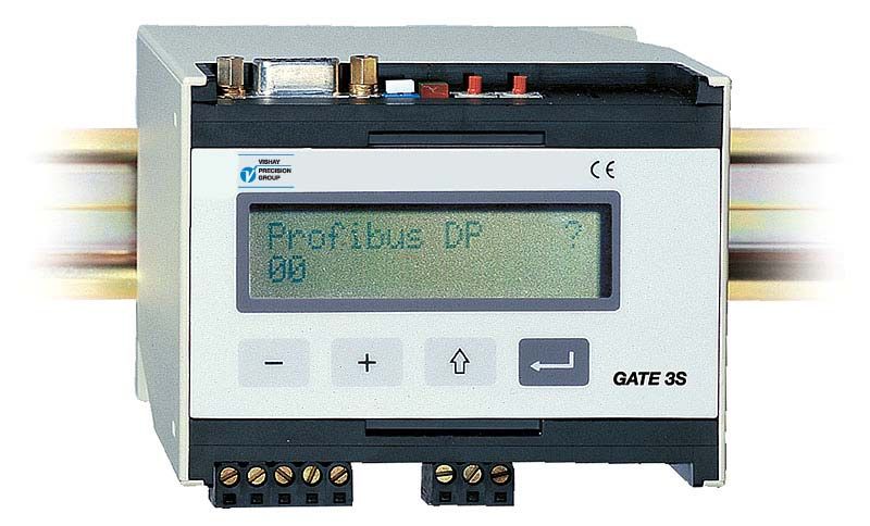
As GATE 3S is in Operating mode the fieldbus type and the operating status
of all network units will be displayed.
Figure 6. GATE 3S front panel during start-up.
4-1Operating and Installation Instructions
Status views, ‘Generation 3’ and E-2-WEI
Figure 7.
During normal operation, the upper line of the first status view shows the type of
fieldbus used for communication with the master. If the fieldbus goes out of operation,
this is indicated by a question mark to the right on the line.
The lower line shows the communication status for the connected slave units.
Each unit, starting with slave 1 to the left, is represented by a symbol:
‘1’ is displayed for a slave unit with correct communication.
‘0’ is displayed for a slave unit with communication error.
’*’ is displayed for a slave unit that is inactivated (the address set to 0).
In operating mode the panel keys have the following functions:
– Switch to previous status view.
+ Switch to next status view.
↑ Brief: Switch to the first status view.
2 seconds Go to ‘Set-up’ mode. (Password may be required.)
↵ 2 seconds: Go to ‘Bus diagnostics’. See page 4-4.
Press + (or – ) to get a status view for one of the measurement instruments
(E-2-WEI or ‘Generation 3’) at a time.
These views contain:
On the upper line, slave number and measurement value or a possible error code.
On the lower line, unit address and weight status for the slave unit.
Briefly press ↑ to switch GATE 3S back to the first status view.
If ↵ is pressed for 2 seconds, ‘Bus diagnostics’ starts (see page 4-4).
Return to normal operation by pressing the key ↑ .
Start up/Reset
Fieldbus information Profibus-DP Note Note. A question mark ( ? ) here
means that the communication
Network status 1*01 between GATE 3S and the
fieldbus master is erroneous.
2 sec.
Slave no.: Weight 01: -12345.600
Address Weight status 011 Net Motion
2 sec.
Slave no.: Slave status 02: Not in use
2 sec.
Slave no.: Comm.error
for unit 03 03: Error: 255
Address 021
2 sec.
Slave no.: Weight 04: 34567.800
Address Weight status 022 Gross
2 sec.
To 'Bus diagnostics'
Figure 7. Example of display views in GATE 3S with four connected
measurement instruments, ‘Generation 3’ or E-2-WEI.
4-2Fieldbus unit GATE 3S
Status views, microPOS
Figure 8.
During normal operation, the upper line of the first status view shows the type of
fieldbus used for communication with the master. If the fieldbus goes out of operation,
this is indicated by a question mark to the right on the line.
The lower line shows the communication status for connected microPOS units.
Each unit, starting with slave unit 1 to the left, is represented by a symbol:
‘1’ is displayed for a unit with correct communication.
‘0’ is displayed for a unit with communication error.
’*’ is displayed for a slave unit that is inactivated (the address set to 0).
In operating mode the panel keys have the following functions:
– Switch to previous status view.
+ Switch to next status view.
↑ Brief: Switch to the first status view.
2 seconds Go to ‘Set-up’ mode. (Password may be required.)
↵ 2 seconds: Go to ‘Bus diagnostics’. See page 4-4.
Press + (or – ) to get a status view for one of the microPOS units at a time.
The upper line shows: slave number, setpoint value 1, a question mark
if writing is not enabled, setpoint value 2.
By communication error each setpoint value is replaced by ‘- - - - - -’.
The lower line shows: status indicators for servo 1 and servo 2, feedback
value 1, feedback value 2. The status indicators may be:
‘+’ = in position, (blank = not in pos.), ‘?’ = not controlled.
By communication error each feedback value is replaced by ‘- - - - - -’.
Briefly press ↑ to switch GATE 3S back to the first status view.
If ↵ is pressed for 2 seconds, ‘Bus diagnostics’ starts (see page 4-4).
Return to normal operation by pressing the key ↑ .
Start up /Reset
Note. A question mark ( ? ) here
Note means that the communication
Fieldbus information Profibus-DP between GATE 3S and the
Communication status for connected 1*01 fieldbus master is erroneous.
microPOS units Setpoint values in the status
2 sec. views for all microPOS units are
replaced by '- - - - - - - - - - - -'.
Slave number: setpoint 1 ,setpoint 2 01:655.35 655.35
1 in pos, 2 in pos, feedback1, feedback 2 ++ 655.35 655.35
2 sec.
Slave number: Slave status 02: Not in use
Slave number: setpoint 1, writing not 2 sec.
possible, setpoint 2 03:655.35?655.35
Communication error for slave 03 ?? ------ ------
2 sec.
Slave number: setpoint 1, setpoint 2 04:218.00 218.00
1 in pos, 2 not controlled, feedback 1 +? 218.00
2 sec.
To 'Bus diagnostics'
Figure 8. Example of status views in GATE 3S with four microPOS servo units.
4-3Operating and Installation Instructions
Bus diagnostics
Bus diagnostics gives the possibility to study the byte contents of a selected
part of the GATE 3S memory during normal operation. This function is very useful for
specialist troubleshooting in case of communication problems.
(Press ↑ to return to normal status views.)
To activate ‘Bus diagnostics’, press ↵ for 2 seconds as the status view
for a selected slave unit is shown.
Output memory byte values, in hexadecimal form, starting with the first bytes
for the selected slave unit, are presented on the two display lines.
Each line starting with ‘o’ for output and the number of the first byte on the line.
Use the panel keys + and – to step forwards and backwards in the memory.
Press ↵ to switch over to input bytes.
Input memory byte values, in hexadecimal form, starting with the first bytes
for the selected slave unit, are presented on the two display lines.
Each line starting with ‘i’ for input and the number of the first byte on the line.
Use the panel keys + and – to step forwards and backwards in the memory.
Now ↵ can be used to switch between display of the latest view
of output memory bytes and input memory bytes respectively.
Press ↑ to finish the ‘Bus diagnostics’ and get back to the status view for one unit.
Profibus-DP
11101
2: -12345.600
Net Motion
o006 00 0D EF ED o014 EF ED 0F FD
o010 0D EF FD DD o018 0F FD EF 00
i006 FE DE F0 DF i014 EF ED 0F FD
i010 F0 DF FE 00 i018 0F FD EF 00
Figure 9. Example showing how ‘Bus diagnostics’ is used to study
output and input bytes for slave unit number two in the network.
4-4Fieldbus unit GATE 3S
5. Communication
GATE 3S connects to a network of measurement instruments or servo units
through a serial communication port.
For the fieldbus communication GATE 3S uses an internal transfer module.
Transfer modules for several common fieldbus types are available.
Serial communication interface
The serial communication utilises RS-485 / RS-422 on 2-wires or 4-wires for
transmission via Modbus RTU. RS-485 / RS-422 is an interface working with
differential voltages, giving a noise resistant transmission in networks with
several slave units and long distances.
To ensure good communication, correct termination of the transmission line
at both ends is required.
See section 2. Installation.
Memory mapping in GATE 3S
Data transmission in GATE 3S is performed by messages that are written into
a memory, where they can be read from another unit.
The messages can be either 6 bytes or 20 bytes long, depending on the setting
of parameter ‘GATE 3S mode’.
6 byte mapping is used for microPOS servo units and for ‘Generation 3’ units
(AST 3, TAD 3, WEI 3) when high transmission speed is needed.
20 byte mapping is used for E-2-WEI transmitters and for ‘Generation 3’ units
when transmission of large amounts of data is needed.
Data representation
All data in GATE 3S is stored with the most significant byte on the lower memory
address (Motorola format).
If the fieldbus master uses data with the most significant byte on the higher memory
address (Intel format), the bytes need to be swapped in the master.
Examples:
Used in GATE 3S.
Value Bytes (Motorola) Bytes (Intel)
1234.9 (floating point) 44 9A 5C CD CD 5C 9A 44
123456789 (32 bit) 07 5B CD 15 15 CD 5B 07
12345 (16 bit) 30 39 39 30
As you can see the byte order is swapped in the two implementations.
You can use the Bus diagnostics to study the byte sequence.
5-1Operating and Installation Instructions
‘Generation 3’ (AST 3, TAD 3, WEI 3), 6 byte mapping
In GATE 3S, 6 bytes of memory is assigned for each slave unit in the network, as
shown in the table to the left below.
Slave 1 uses the bytes 00 through 05 (and slave 9 uses the bytes 48 through 53)
according to the tables in the middle below.
The first byte to the fieldbus (00 or 48 in the tables below) is used for a status report.
In the table to the right the meaning of each status bit is explained.
Status, byte 00 (48)
Memory Slave 1 to fieldbus
From To Meaning
Bytes Slave Byte fieldbus fieldbus Bit of bit = 1
00 - 05 1 00 Command */ Status 0 Good zero ***/
06 - 11 2 01 – Instr. error **/ 1 Net mode ***/
MSB
12 - 17 3 02 – Displ.weight 2 Motion ***/
18 - 23 4 03 – -”- 3 Relay 1 activated
24 - 29 5 04 – -”- 4 Relay 2 activated
30 - 35 6 05 – -”- 5 Power failure
36 - 41 7 6 Above level 1
42 - 47 8 Slave 9 7 Above level 2
48 - 53 9 48 Command */ Status
54 - 59 10 49 – Instr. error **/
MSB
60 - 65 11 50 – Displ.weight
66 - 71 12 51 – -”-
72 - 77 13 52 – -”-
78 - 83 14 53 – -”-
84 - 89 15
90 - 95 16
*/ See section Communication, Command register, in the manual for the unit.
**/ Error code 255 means communication error between the slave and GATE 3S.
For other error codes, see section Troubleshooting in the manual for the slave.
***/ For AST 3 the function is not supported, the bit is always ‘0’.
If a power failure has occurred, bit 5 in the ‘Status’ byte is set to 1.
Sending Command 202 to the unit will set this bit to 0.
NOTE! An action is activated only as the command value is changed.
Thus, activation of a certain action one more time, must be
preceded by a different command, for example 00, ‘No action’.
5-2Fieldbus unit GATE 3S
Weight value representation for ‘Generation 3’, 6 byte mapping
A weight value is stored in GATE 3S as integer values or as a floating point value,
depending on the setting of parameter ‘Weight format’:
• Integer The first data word (16 bit) is the integer part of the value, and
the second data word is the decimal part of the value, times 1000 to make it
an integer.
The words are signed integers, so they can represent both positive and
negative values.
• Float The weight is represented as a 32 bit floating point value ,
according to IEEE standard.
NOTE: Fieldbus masters using ‘Intel format’ will need to swap the bytes.
Examples:
Integer representation of weight values from slave unit 1:
Value Address Data Bytes Bits
123.5 02 03 123 00 7B ( 0000 0000 0111 1011 )
04 05 0.5 * 1000 = 500 01 F4 ( 0000 0001 1111 0100 )
123.456 02 03 123 00 7B ( 0000 0000 0111 1011 )
04 05 0.456 * 1000 = 456 01 C8 ( 0000 0001 1100 1000 )
12345.6 02 03 12345 30 39 ( 0011 0000 0011 1001 )
04 05 0.6 * 1000 = 600 02 58 ( 0000 0010 0101 1000 )
-123.4 02 03 -123 (2’s compl.) FF 85 ( 1111 1111 1000 0101 )
04 05 -0.4 * 1000 = -400 FE 70 ( 1111 1110 0111 0000 )
Range for the values will be -32768 to +32767 (with 0 to 3 decimals added).
A correct complete value is accomplished in the master computer by dividing
the second word value by 1000 and adding the result to the first word value.
Float representation of weight value from slave unit 1:
Value Address Bytes
123.5 02 03 42 F7
04 05 00 00
5-3Operating and Installation Instructions
‘Generation 3’ (AST 3, TAD 3, WEI 3), 20 byte mapping
In GATE 3S, 20 bytes of memory is assigned for each slave unit in the network, as
shown in the table to the left. To the right, the byte use for slave 1 is shown.
‘Generation 3’ (AST 3, TAD 3, WEI 3), 20 byte mapping
Memory Unit 1
Bytes Slave Byte From fieldbus To fieldbus
00 - 19 1 00 Command */ Command ack.
20 - 39 2 01 Nbr of registers to write Instrument error **/
MSB
40 - 59 3 02 Read/Write start address Displ.weight, 32 bit
60 - 79 4 03 Read/Write start address -”-
MSB
80 - 99 5 04 Write register 1 -”-
100 - 119 6 05 Write register 1 -”-
MSB MSB
120 - 139 7 06 Write register 2 No. of decimals
140 - 159 8 07 Write register 2 -”-
MSB
160 - 179 9 08 Write register 3 Status register 1 ***/
180 - 199 10 09 Write register 3 Status register 1 ***/
MSB
200 - 219 11 10 Write register 4 Status register 2 ***/
220 - 239 12 11 Write register 4 Status register 2 ***/
MSB MSB
240 - 259 13 12 Write register 5 Read start address
260 - 279 14 13 Write register 5 Read start address
MSB MSB
280 - 299 15 14 Write register 6 Read register 1
300 - 319 16 15 Write register 6 Read register 1
MSB MSB
16 Write register 7 Read register 2
17 Write register 7 Read register 2
MSB MSB
18 Write register 8 Read register 3
19 Write register 8 Read register 3
*/ See section Communication, Command register, in the manual for the slave.
**/ Error code 255 means communication error between the slave and GATE 3S.
For other error codes, see section Troubleshooting in the manual for the slave.
***/ See section Communication, Status register 1 and 2, in the manual for the slave.
Three special commands are possible to use by 20 byte mapping of ‘Generation 3’:
Command 200. Command to write. The following bytes should contain the number
of write registers, the address where the writing should start, and finally up to 8
registers that will be written to the slave unit.
Command 201. Command to select a ‘read window’, three registers wide that will
be included in the messages from the slave unit. The bytes 02 and 03 in the table
above should contain the address of the first register in the read window.
Command 202. If a power failure has occurred, bit 4 in ‘Status register 2’
is set to 1. Sending Command 202 to the slave unit will reset this bit to 0.
NOTE! An action is activated only as the command value is changed. Thus, activation
of a certain action one more time, must be preceded by a different command,
for example 00, ‘No action’. Reading and writing of set-up parameters in AST 3
through GATE 3S is not possible. Only process parameters are available.
The command acknowledgement (byte 00) is either the code of the performed command,
or an error code, 250 through 255, if the command is not performed.
5-4Fieldbus unit GATE 3S
Weight value representation for ‘Generation 3’, 20 byte mapping
A weight value (byte 02 – 07 for slave 1) is stored in GATE 3S as an integer value or
as a floating point value, depending on the setting of parameter ‘Weight format’.
• Integer: Byte 02 – 05 for slave 1 are used as one 4-byte integer value (with sign),
and byte 06 and 07 for slave 1 define the number of decimals in the value.
• Float: The weight (byte 02 – 05 for slave 1) is represented as a 32 bit floating point
value, according to IEEE standard. Byte 06 and 07 for slave 1 define the number of
significant decimals.
NOTE: Fieldbus masters using ‘Intel format’ will need to swap the bytes.
Examples:
Integer representation of a weight value from slave unit 1:
Value Address Bytes
12345.678 02 03 04 05 00 BC 61 4E (12345678)
Number of decimals 06 07 00 03 (3)
Calculations in decimal numbers:
First multiply the most significant word (byte 02 03) by 216 (65536) and
add the least significant word (byte 04 05) to that value.
188 (00 BC) * 216 + 24910 (61 4E) = 12345678
Then divide by 1000, as the number of decimals is 3.
12345678 / 1000 = 12345.678
Float representation of a weight value from slave unit 1:
Value Address Bytes
123.5 02 03 42 F7
04 05 00 00
Messages for ‘Generation 3’, 20 byte mapping
In the message from the fieldbus the first byte (00 for slave unit 1) is a command
to the slave. The remaining bytes are explained in the following examples.
Ex.: Set ‘Level 1 value’ to 123.5 for AST 3, slave unit 1. (Float value)
Command 200 is used for this type of message. Make sure the previous command was
not command 200. Prepare the message and finish by setting byte 00 to 200.
1. Use byte 01 to define the number of registers (2).
2. Use byte 02 and 03 to define the start address, 40234, for the writing.
See AST 3 Technical Manual, Register description.
3. Use the following four bytes to set the value to 123.5.
4. Finally set byte 00 to the command number, 200.
Byte (slave 1) Description Dec Hex
00 Command 200 C8
01 Number of registers to write 2 02
02 03 Start address 40234 9D 2A
04 05 06 07 Write register 1 and 2 123.5 42 F7 00 00
5-5Operating and Installation Instructions
Ex.: Set ‘Level 1 value’ to 20.0 for AST 3, slave unit 1. (Integer value)
Command 200 is used for this type of messages. Make sure the previous command
was not command 200. Prepare the message and finish by setting byte 00 to 200.
1. Use byte 01 to define the number of registers (3).
2. Use byte 02 and 03 to define the start address, 40031, for the writing.
See AST 3 Technical Manual, Register description.
3. Use the following six bytes to set the value to 20.0, i.e. 200 and one decimal.
4. Finally set byte 00 to the command number, 200.
Byte (slave 1) Description Dec Hex
00 Command 200 C8
01 Number of registers to write 3 03
02 03 Start address 40031 9C 5F
04 05 06 07 Write register 1 and 2 200 00 00 00 C8
08 09 Write register 3 1 00 01
Ex.: Set a read window to start at 40031 in AST 3, slave unit 1.
Command 201 is used to set a read window. Make sure the previous command
was not command 201. Prepare the message and finish by setting byte 00 to 201.
The number of registers to read is always three and cannot be changed,
so the contents of byte 01 have no influence.
1. Use byte 02 and 03 to define the start address, 40031, for the reading .
2. Finally set byte 00 to the command number, 201.
Byte (slave 1) Description Dec Hex
00 Command 201 C9
01 (Number of registers to read) – –
02 03 Start address 40031 9C 5F
In the message to the fieldbus (the fieldbus master)
– the first byte (00) is a command acknowledgement,
either the code of the command that is performed or
an error code, 250 through 255, if the command is not performed.
– the second byte (01) is an explanation of a possible error in slave unit 1,
using the error codes described in the manual for the unit.
– the third through eighth bytes (02 through 07) contain the weight value.
– the following four bytes (08 through 11) contain the Status register 1
and Status register 2 for slave unit 1.
– the last eight bytes (12 through 19) contain the start address of the read window
and three registers that are read from slave unit 1.
5-6Fieldbus unit GATE 3S
20 byte mapping for E-2-WEI
In GATE 3S, 20 bytes of memory is assigned for each slave E-2-WEI in the network, as
shown in the table to the left below.
Slave 1 uses the bytes 00 through 19 as shown in the table to the right.
Bytes 00 through 09 from the fieldbus are not used. Byte 10 and 11 are used
for a command and bytes 12 through 19 are used for two setpoint values.
Bytes 00 through 03 to the fieldbus are used for error and status information, bytes
04 through 19 are used for gross weight, net weight, and setpoint values.
Commands, weight status, weight error codes, and data representation
are explained on the following pages.
Memory Unit 1
Bytes Slave Byte From fieldbus To fieldbus
MSB
00 - 19 1 00 – Weight error code
20 - 39 2 01 – Weight error code
MSB
40 - 59 3 02 – Weight status
60 - 79 4 03 – Weight status
MSB
80 - 99 5 04 – Gross Weight Integer
100 - 119 6 05 – Gross Weight Integer
MSB
120 - 139 7 06 – Gross Weight Decimal
140 - 159 8 07 – Gross Weight Decimal
MSB
160 - 179 9 08 – Net Weight Integer
180 - 199 10 09 – Net Weight Integer
MSB MSB
200 - 219 11 10 Command Net Weight Decimal
220 - 239 12 11 Command Net Weight Decimal
MSB MSB
240 - 259 13 12 Setpoint 1 Integer Setpoint 1 Integer
260 - 279 14 13 Setpoint 1 Integer Setpoint 1 Integer
MSB MSB
280 - 299 15 14 Setpoint 1 Decimal Setpoint 1 Decimal
300 - 319 16 15 Setpoint 1 Decimal Setpoint 1 Decimal
MSB MSB
16 Setpoint 2 Integer Setpoint 2 Integer
17 Setpoint 2 Integer Setpoint 2 Integer
MSB MSB
18 Setpoint 2 Decimal Setpoint 2 Decimal
19 Setpoint 2 Decimal Setpoint 2 Decimal
5-7Operating and Installation Instructions
Commands for E-2-WEI
By the Command register (byte 10 and 11 from the fieldbus to E-2-WEI slave 1)
a number of actions in E-2-WEI can be activated. The meaning of each register value
for Command is explained in the table below.
Command value
Dec Hex Action activated in E-2-WEI
0 00 00 No action is activated.
1 00 01 Activate setpoint relay 1.
2 00 02 Deactivate setpoint relay 1.
3 00 03 Activate setpoint relay 2.
4 00 04 Deactivate setpoint relay 2.
5 00 05 Activate setpoint relay 1 and 2.
6 00 06 Deactivate setpoint relay 1 and 2.
7 00 07 Auto tare.
8 00 08 Set to zero.
9 00 09 Select gross mode.
10 00 0A Select net mode.
11 00 0B Select normal weight.
12 00 0C Select calibration value.
13 00 0D
– 65535 – FF FF No action is activated.
NOTE! An action in E-2-WEI is activated only as the command value is changed.
Thus, activation of a certain action one more time, must be preceded by
a different command, for example ‘No action is activated’ (0).
Weight status for E-2-WEI
Weight status indication for E-2-WEI is transmitted in bytes two and three
to the fieldbus (bytes 02 and 03 for slave 1), bit 15 being the most significant bit.
In these two bytes, bits 0 – 5 and 8 – 11 are valid only by valid weight,
i.e. as the error code, the first two bytes to the fieldbus, is = 00.
Byte 02 + 03 to the fieldbus for slave 1
Bit Meaning of bit = 1 Bit Meaning of bit = 1
0 Gross weight negative. 8 Relay 1 active.
1 Net weight negative. 9 Relay 2 active.
2 Motion. 10 Relay 1 cycle done.
3 Good zero, current weight. 11 Relay 2 cycle done.
4 Net mode. (Bit = 0, Gross mode.) 12 Not used.
5 Calibration resistor connected. 13 Good zero, gross weight.
6 Overload/Underload. 14 Good zero, net weight.
7 Overrange/Underrange. 15 Not used, always zero.
A ‘relay cycle done’ bit is cleared when the relay is not active
and a new setpoint value is entered.
5-8Fieldbus unit GATE 3S
Weight error codes for E-2-WEI
Possible weight error information is transmitted to the fieldbus as
an error code in the two first bytes (00 and 01 for E-2-WEI slave 1).
During shunt calibration, error code 19 is transmitted and the calibration value
replaces the gross weight (bytes 04 through 07 for E-2-WEI slave 1).
By all other weight error codes, except code 00 ‘no error’, the weight values
(bytes 04 through 11 for E-2-WEI slave 1) are set to zero.
Error code Explanation
00 Valid ‘normal’ weight (no error).
10 Excitation short-circuit.
11 Sense voltage error.
12 Transducer signal error.
13 Transducer signal out of range.
14 Invalid A/D signal.
16 Underload or underrange. See also Weight status, bit 06 and 07.
17 Overload or overrange. See also Weight status, bit 06 and 07.
18 Integer part of weight value, gross or net weight, too high (>32767).
19 Calibration resistor connected.
The calibration value is found in the gross weight register.
255 Communication error.
Data representation
All data values are stored in GATE 3S as integer values.
NOTE: Fieldbus masters using ‘Intel format’ will need to swap the bytes.
Examples:
Integer value representation of gross weight values to the fieldbus from slave 1:
Value Address Data words Bytes Bits
123.5 04 05 123 00 7B ( 0000 0000 0111 1011 )
06 07 0.5 * 1000 = 500 01 F4 ( 0000 0001 1111 0100 )
123.456 04 05 123 00 7B ( 0000 0000 0111 1011 )
06 07 0.456 * 1000 = 456 01 C8 ( 0000 0001 1100 1000 )
12345.6 04 05 12345 30 39 ( 0011 0000 0011 1001 )
06 07 0.6 * 1000 = 600 02 58 ( 0000 0010 0101 1000 )
-123.4 04 05 -123 (2’s compl.) FF 85 ( 1111 1111 1000 0101 )
06 07 -0.4 * 1000 = -400 FE 70 ( 1111 1110 0111 0000 )
Range for the values will be -32768 to +32767 (with 0 to 3 decimals added).
A correct complete value is accomplished in the master computer by dividing
the second word value by 1000 and adding the result to the first word value.
5-9Operating and Installation Instructions
6 byte mapping for microPOS
In GATE 3S, 6 bytes of memory is assigned for each slave unit in the network,
as shown in the table below to the left.
Unit 1 uses the bytes 00 through 05 as shown in the table in the middle.
The two last bytes to the fieldbus (04 and 05 in the example) are used for a status
report, the meaning of the status bits is shown in the table to the right.
Status
Memory Slave unit 1 Byte 04 + 05 to fieldbus
Slave From To Meaning
Bytes unit Byte fieldbus fieldbus Bit of bit = 1
00 - 05 1 00 S1, setpoint MSB S1, feedback MSB
0 Servo 1 controlled
06 - 11 2 01 S1, setpoint S1, feedback 1 Servo 1 in position
12 - 17 3 02 S2, setpoint MSB S2, feedback MSB
2 Servo 2 controlled
18 - 23 4 03 S2, setpoint S2, feedback 3 Servo 2 in position
MSB
24 - 29 5 04 Slave control. Status 4 Dig. inp.1 high
30 - 35 6 05 – Status 5 Dig. inp.2 high
36 - 41 7 6 Dig. inp.3 high
42 - 47 8 Meaning 7 Dig. inp.4 high
48 - 53 9 Bit of bit = 1 8 Dig. inp.5 high
54 - 59 10 0 – 9 –
60 - 65 11 1 – 10 –
66 - 71 12 2 – 11 –
72 - 77 13 3 – 12 –
78 - 83 14 4 – 13 –
84 - 89 15 5 – 14 –
90 - 95 16 6 – 15 –
7 Write */
enable
*/ Writing of new values to the slave unit microPOS is possible only as bit 7
in byte 04 from the fieldbus is set to 1.
This gives a protection, preventing GATE 3S from changing the setpoint values if,
as a consequence of a power interruption, the fieldbus master sets all bytes to 00.
If bit 7 is not = 1, this is indicated in the status view. See figure 8.
Data representation
Example:
Representation of feedback value from servo 1 in microPOS slave unit 1:
Value Data Bytes Bits
123.50 12350 30 3E ( 0011 0000 0011 1110 )
A correct complete value is accomplished in the master computer by dividing
the data by 100.
Range for the values: 0.00 to 655.35
5-10Fieldbus unit GATE 3S
6. Troubleshooting
General
GATE 3S has an automatic error checking facility. This serves to facilitate
troubleshooting and to ensure that the instrument will function in the best
possible manner. If an error occurs, an error code and a short message
describing the error will be displayed.
Below some hints are given on how to correct errors and faults.
Start-up errors
These error codes can only appear during start-up.
Error Explanation
code
080 Invalid set-up version.
This error usually occurs at first start-up after a program upgrade.
The actual settings have been replaced by default values.
Enter set-up mode, perform the necessary editing and
save the new parameter settings.
081 Invalid set-up data.
Indicates faulty parameter checksum.
The actual settings have been replaced by default values.
Enter set-up mode, perform the necessary editing and
save the new parameter settings.
097 RAM error.
RAM memory error is a fatal error. It indicates equipment failure that
requires trained service personnel. The distributor must be contacted.
098 FLASH error.
Flash memory error is a fatal error. It indicates equipment failure that
requires trained service personnel. The distributor must be contacted.
099 Watchdog error.
If a watchdog error appears the system will be reinitialised. The operator
must then power the instrument off and on, to achieve normal operation.
The program regularly sends impulses to a special watchdog circuit to
ensure that the circuits and the program operate correctly.
However, if these impulses for any reason are omitted the watchdog
error indication will result.
6-1You can also read