MAGIC THIPPRO INTERCOM - CONFIGURATION GUIDE - AVT - AUDIO VIDEO TECHNOLOGIES GMBH
←
→
Page content transcription
If your browser does not render page correctly, please read the page content below

MAGIC THipPro
          Intercom
                  Configuration Guide

                  Version 3.020 (19 February 2019)
       © 2019, AVT Audio Video Technologies GmbH
MAGIC THipPro
        Intercom
          Hardware &
           Interfaces

                        2
Five Status-LEDs
▪ POWER, SYNC, ALARM, INFO 1, INFO 2
Illuminated graphic display with 160 x 32 pixels & front keypad
▪ For basic settings and status displays, but not for operation.
Front View
3
Two independent LAN interfaces for control and 2 x analogue Audio input/output
VoIP applications. ▪ Je 2 x XLR (female/male)
Word clock input/output 4 x AES Audio input/output
Programmable GPIO interface ▪ 8 x digital audio cable (2 x Sub-D 15-polig)
▪ 8 x TTL input/output 2 x Slot for DANTE/LAN modules
▪ 8 x Relays (8 x normally open contact)
Rear view without modules
4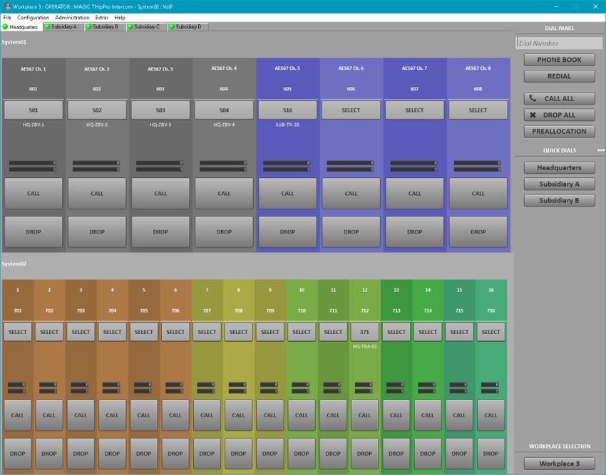
Slot 1: LAN 3/4 Slot 2: DANTE
▪ 2 additional Ethernet interfaces ▪ 32 channels
▪ Flexible use e.g. for control, VoIP, ▪ 2 Ethernet interfaces
Ember+, DHD Set Logic, SNMP ▪ The classic audio interfaces can still be
used.
Available modules
5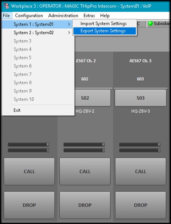
19” housing x 1 U DHD Set Logic
▪ 96 inputs/outputs
Without fan for silent operation
Ember+ provider
Low power consumption of typ. 15 W
▪ 96 inputs and 96 outputs
Two system variants ▪ Keypad, phone number, name
▪ 8 caller lines, expandable to 16 caller lines
Ember+ Consumer
▪ 16 caller lines
▪ Connection to 2 Ember+ providers
12 audio interfaces ▪ 20 functions per consumer
▪ 2 x analogue input/output
DTMF generator for the transmission of DTMF tones
▪ 8 x digital input/output (4 x AES)
▪ 2 x handset/headset VLAN support
Digital signal processing for each line QoS support
▪ Echo canceller to eliminate echoes with a runtime of up to 120
ms (Echo Tail Time)
integrated SIP monitor
▪ AGC Automatic Gain Control Audio test panel with signal generator
▪ Expander for noise suppression
Programmable GPIO for mixing console control and external
signalling
Features
6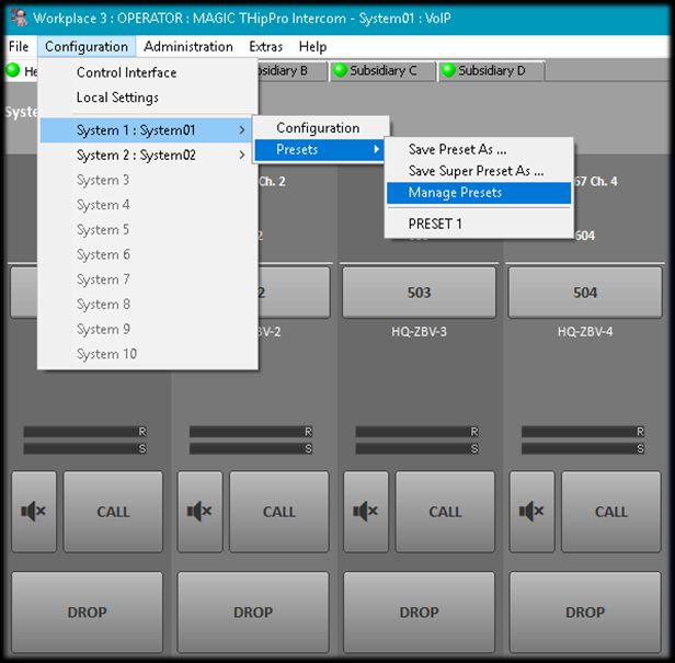
MAGIC THipPro Intercom PC ▪ 6 workplace configurations
Software 8 or 16 VoIP lines
▪ Single user license (1 licence
included, optionally up to 20 per HD Voice
system). ▪ Significantly better voice quality with
▪ Up to 10 systems with 160 lines can G.722 codec.
be displayed simultaneously.
Pretalk via USB Headset
▪ Grouping of the systems on up to 10
pages. AES67
▪ Resolution independent design. ▪ Audio over IP
▪ Supported operating systems ▪ 8 Channels (in addition to hardware
Windows 7, Windows 8.1, Windows 10 audio interfaces).
32/64 Bit
▪ Free colour design
Available options
7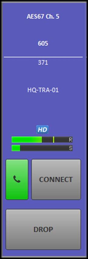
MAGIC THipPro
        Intercom
         PC Software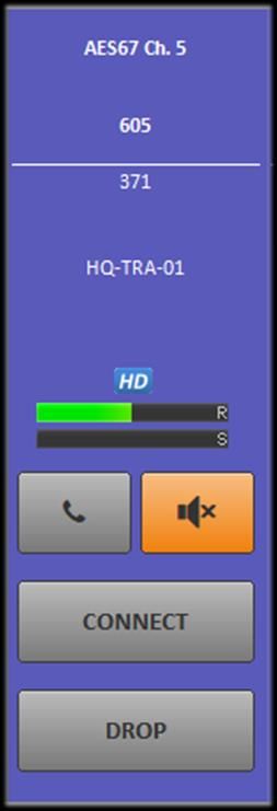
Install the MAGIC THipPro Intercom Software from
the USB stick with administrator rights on your PC
and then start the software with administrator
rights.
▪ From Windows 7 and higher via the context menu "Run
as administrator", even if you are currently logged on
as administrator.
Under MENU → CONFIGURATION → CONTROL
INTERFACE, enter the systems to be controlled.
Add systems by double-clicking a line or use the
ADD/EDIT key.
Remove a system using DELETE.
DELETE ALL removes all entries from the list.
The order of the entries can be changed via UP
and DOWN. The sequence determines the order
of the systems in the main window.
Starting the PC Software
9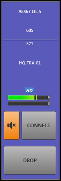
INTERFACE: The connection can only be
established via the LAN interface (UDP).
PARAMETERS:
▪ INTERFACE: If the PC has several network interfaces,
specify here which of them is to be used.
▪ IP ADDRESS: IP address of the THipPro Intercom
device.
▪ PORT: UDP port of the control connection on the
THipPro Intercom device. The default value is 10 000.
Press the right telephone key on the device twice
to display the currently assigned IP address of the
system,.
The network settings can be adjusted on the
device under MENU → SYSTEM SETTINGS →
LAN SETTINGS.
Connection parameters
10 The software can connect to up to 10 THipPro Intercom
systems simultaneously.
The THipPro Intercom systems can be distributed over up to
10 pages.
The pages are selected via the tabs () below the menu
bar.
Depending on the screen resolution, up to 10 THipPro
Intercom systems with 160 lines can be displayed
simultaneously on one page.
On the right-hand side you will find:
▪ () Telephone book, Redial list and the input field for the
telephone number.
▪ () Keys for the Preallocation of lines.
▪ () Quick dial keys and last calls list. Click on the list title to
switch between the two views.
▪ () The WORKPLACE SELECTION key to switch the view
to an alternative workplace configuration.
Main Window
11 A telephone connection can be established in
various ways:
▪ Enter the phone number in the phone number field ()
and press the CALL key () on the desired line.
▪ Select a phone book entry (). The phone number is
then transferred to the phone number field. Press the
CALL key () on the desired line.
▪ Select a redial number () and press the CALL key ()
on the desired line.
▪ Select a number from the LAST CALLS list () and
press the CALL key () on the desired line.
▪ Press the CALL key () on the desired line. A dialling
window opens where you can select a directory entry or
enter a telephone number.
▪ Select a quick dial key () and press the CALL key ()
on the desired line.
Call set-up
12 A click on the level indicator () opens
the send level booster.
The level of the outgoing signal can be
increased in three steps.
The individual levels are configurable
(SYSTEM CONFIGURATION →
SIGNAL PROCESSING → SEND
LEVEL BOOSTER).
The currently set gain is highlighted in
yellow.
The gain is reset after a connection is
terminated.
Level booster
13 A key () for local
communication with the
subscriber can be displayed for
all lines (activate under
CONFIGURATION → LOCAL
SETTINGS → PRETALK
STREAMING).
This pretalk is conducted via the
PC's sound card.
The audio data streams are
transferred between the PC and
the THipPro Intercom System via
LAN.
Pretalk
14 A key () to hold the connection can be displayed
for all lines (activate under SYSTEM
CONFIGURATION → INTRO / HOLD SIGNAL).
The position of the key depends on whether the
pretalk function is activated.
The received audio signal will no longer be output
to the audio interface.
The following signals may be played to the caller:
▪ Intro: A short announcement, individual for each line
stored on the THipPro Intercom system.
▪ External: A signal fed via a separate audio interface.
▪ Line: The signal from the audio interface assigned to
the telephone line.
Hold
15 An R key () can be displayed for all lines
to transfer calls to up to 10 predefined
destinations () (enable under
CONFIGURATION → LOCAL SETTINGS
→ QUICK DIALS / CALL TRANSFER).
In the CONNECT () state, the connection
is transferred directly (blind call transfer).
In the PRETALK () state, the desired party
is notified (attended call transfer).
▪ The symbol of the R key changes to an arrow
(). The call can be retrieved.
▪ The DROP key () completes the call transfer.
Call Transfer
16 A telephone connection can also be prepared and
established at a later time.
The SELECT () key opens the phone book:
▪ An entry can be searched for () and selected () here and
the preallocation can be completed by pressing the SELECT
key ().
▪ If several numbers are stored for an entry, the
preallocation is completed by clicking on the desired
number ().
▪ If the desired number is not yet stored in the phone
book, a new entry must be created using the NEW ()
key.
▪ The CLEAR key () deletes the preallocation on this
line.
Preallocation is also possible without a database:
▪ The SELECT () key opens a keypad.
▪ Here you can enter a number and complete the
preallocation by pressing the SELECT key.
▪ The CLEAR key () deletes the preallocation on this
line.
Preallocation of lines (1)
17 The CALL ALL () key is
used to establish telephone
connections on all
preassigned lines of all
THipPro Intercom systems.
The DROP ALL () key
terminates all active
telephone connections on
all THipPro Intercom
systems.
Preallocation of lines (2)
18 The preallocation of all lines of all THipPro
Intercom systems can be stored in a preallocation
record in the database.
Each THipPro Intercom system must be assigned
an individual system index under SYSTEM
CONFIGURATION → GENERAL → SYSTEM →
INDEX.
Preallocation records are managed via the
PREALLOCATION key ():
▪ CLEAR ALL () clears the preallocations of all THipPro
Intercom systems.
▪ LOAD () displays all preallocation records stored in
the database.
▪ SAVE () stores the lines currently preallocated on the
THipPro Intercom systems as preallocation records in
the database. Select under SAVE AS to create
a new record. Select an existing record under SAVE
AS to overwrite it.
▪ Individual preallocation records can be deleted from the
database using DELETE ().
Preallocation of lines (3)
19MAGIC THipPro
Intercom
Local Settings
Settings stored on the PC.
20 All Settings under CONFIGURATION → LOCAL SETTINGS
are stored on the PC.
On page APPLICATION PARAMETER you can specify:
▪ MAIN WINDOW PRESENTATION: The size of the program
window in pixels.
▪ LAYOUT: Arrangement of the THipPro Intercom systems on
the main window:
COLUMNS: Number of systems next to each other.
ROWS: Number of systems on top of each other.
HIDE UNITS WITHOUT CONFIGURED IP ADDRESS: Gaps in
the list of systems under CONTROL INTERFACE can
optionally be skipped.
▪ SYSTEM APPEARANCE: Arrangement of the caller lines of
the individual THipPro Intercom devices:
LINES PER SYSTEM: One or two line display of a THipPro
intercom system.
CALLER LINES PER LINE: Number of caller lines of a THipPro
Intercom System per line.
◦ UNIFORM WIDTH: All lines have the same width.
◦ MIN X: At least X caller lines per line.
◦ 16: 16 caller lines per line
▪ SIDE BAR SIZE: Width of the sidebar of the main window in
pixels.
Application Parameters (1)
21 PAGE LABELS: Labelling of the tabs in the main window.
PLAY WAVE FILE: The PC software can play audio files in WAVE
format to signal the following events:
▪ ON INCOMING CALL: Activates the playback of an audio file when a call
arrives on a line of the THipPro Intercom system.
▪ ON REMOTE DROP: Activates the playback of an audio file when the
telephone connection has been terminated by the remote side.
▪ ON LOCAL DROP: Enables playback of an audio file when the telephone
connection has been disconnected from the local side.
▪ A file name can be specified for incoming and outgoing calls respectively. If
the file name or path contains the symbol "%d", a separate audio file will be
played for each line. In the example, Warning_%d.wav expands to
Warning_1.wav for line 1,
Warning_2.wav for line 2, and so on
LOGFILE: A log file is saved on the PC for each day of the month.
After one month the files are overwritten.
▪ LOGFILE FOLDER: The storage path of the log files can be selected via
BROWSE.
▪ OPEN opens the current log file.
▪ FILE NAME FORMAT: The PC name can be included in the file name of the
log file, e.g. if all log files are stored in a central location.
Application Parameters (2)
22 Up to 20 quick dial entries can be
configured.
▪ NAME: Labelling of the quick dial key.
▪ NUMBER: Telephone number.
▪ The quick dial keys are displayed in the
sidebar of the main window.
Calls can be transferred to up to 10
different numbers.
▪ ENABLE CALL TRANSFER: This activates
the call transfer function. An R key is
displayed on each line in the main window.
▪ NAME: You can optionally specify a name
for a transfer destination.
▪ NUMBER: Telephone number.
Quick Dials / Call Transfer
23 The PC software allows the user to speak directly to the
remote station (software option PRETALK STREAMING
required).
This pretalk is conducted via the PC's sound card.
The audio data streams are transferred between the PC and
the THipPro Intercom System via LAN.
Configure the function on the PRETALK STREAMING
page:
▪ ENABLE PRETALK STREAMING: A pretalk key is displayed
on all lines.
▪ AUDIO INPUT: Select an audio recording device from the
PC.
▪ STREAM TEST SIGNAL TO MAGIC THIPPRO: Sends a test
signal to the remote terminal to check the network connection
to the THipPro intercom system. A telephone connection
must be established in PRETALK mode.
▪ AUDIO OUTPUT: Select an audio output device from the PC.
▪ PLAY TEST SIGNAL ON AUDIO OUTPUT: Plays a test
signal on the PC's audio output device to check the network
connection from the THipPro Intercom system. A telephone
connection must be established in PRETALK mode.
Pretalk Streaming
24 Determine how the settings are stored on
the local PC on page SETTINGS FOLDER:
▪ FOR CURRENT USER: Each user has
separate settings and can change them
themselves.
▪ FOR ALL USERS: All users of the PC use
identical settings. Administrator rights are
needed to change them.
▪ IN THIS FOLDER: The settings are saved to a
file in the specified location.
SAVE SETTINGS ENCRYPTED: The local
settings are stored encrypted.
If you want to create a backup of the local
settings, the command showprofilepath
under ADMINISTRATION → SYSTEM
PANEL shows where the file can be found.
Settings Folder
25MAGIC THipPro
Intercom
System configuration
26 The settings can be found in the CONFIGRATION menu. There is
a submenu for each connected THipPro Intercom device.
CONFIGURATION opens the settings of the respective system:
▪ These settings are stored on the device.
▪ All settings in the OPERATION SETTINGS branch can be saved as
PRESET.
▪ A SUPER PRESET contains all settings under OPERATION SETTINGS
and SYSTEM SETTINGS.
PRESETS and SUPER PRESETS are stored on the device and
can be managed and loaded via CONFIGURATION → SYSTEM X
→ PRESETS.
General
27 Presets are managed via CONFIGURATION →
SYSTEM X → PRESETS:
▪ SAVE PRESET AS: The current configuration of the
OPERATION SETTINGS branch is saved as a Preset.
The name is freely selectable (max. 16 characters).
▪ SAVE SUPER PRESET AS: The entire current system
configuration is saved as a super Preset. The name is
freely selectable (max. 16 characters).
▪ MANAGE PRESETS: Displays a list of all stored
Presets and offers additional management functions:
NEW PRESET: Creates a new Preset based on the
current configuration.
NEW SUPER PRESET: Creates a new super Preset
based on the current configuration.
EDIT: Opens the selected Preset for editing.
SELECT: Activates the selected Preset.
IMPORT: Imports a Preset stored on the PC.
EXPORT: Saves a selected Preset to the PC.
EXPORT ALL: Saves all Presets to the PC.
▪ List of Presets: The menu also displays all available
Presets. Click on a Preset to activate it.
Presets
28 The system configuration can be
stored in a file under FILE → SYSTEM
X → EXPORT SYSTEM SETTINGS.
To restore a backup, open the file
using FILE → SYSTEM X → IMPORT
SYSTEM SETTINGS.
It is also recommended to recreate the
backup file after a firmware update, as
it cannot be guaranteed that old
backups are compatible with the latest
firmware.
▪ In such a case, the device would first have
to be downgraded to the software version
with which the backup file was created.
Backup and restore
29 The local settings are automatically
protected when working under a user
account while FOR ALL USERS is selected
under CONFIGURATION → LOCAL
SETTINGS → SETTINGS LOCATION.
To also protect the system settings, a
password must be set under LOGIN.
Two levels are available:
▪ ADMINISTRATOR: Log in with this password
to access all functions and settings.
▪ USER: Log in with this password to load
presets and switch between workplaces.
Note: If you have forgotten the administrator
password, the device can only be unlocked
by resetting to factory settings.
Login
30MAGIC THipPro
Intercom
Global Settings
Settings that are identical for all connected systems. Optionally, up to 20 PCs can connect
to a THipPro Intercom system.
If the INTERCOM CLIENTS list on the
CLIENTS/SECURITY page is empty,
any PC can connect to the system.
As soon as an entry exists, access
protection is active.
▪ All PCs in the list can connect directly to
the system
▪ On all other PCs, the administrator
password must be entered when
establishing a connection.
Clients / Security
32 Settings made on the GENERAL
page, apply to all systems
simultaneously.
Each workplace configuration can be
assigned a name and a background
colour of the main window.
Customize the buttons off the main
window under BUTTON LABELS.
If BLOCK CALLS FROM NUMBERS
OTHER THAN THE PREALLOCATED
NUMBER is activated the THipPro
Intercom Systems only accept calls
from the respective preallocated
number.
General
33 On the CLIENT
WORKPLACE
ASSIGNMENT page, the
WORKPLACE ACCESS
column specifies which
workplace configurations
the respective clients can
access.
Client Workplace Assignment
34 The phone book is configured on the DATABASE
page.
The phonebook is provided via a Microsoft SQL
database.
▪ Information on installing a free Microsoft SQLExpress
database can be found in the download area of our
website under QUICK GUIDES in the document SQL
SERVER 2012 INSTALLATION.
Enable the DATABASE and enter the following
information:
▪ SQL SERVER: IP address or computer name of the PC
on which the SQL Server is installed and - if available -
the SQL Server instance.
▪ DATABASE: Name of the database
▪ USER
▪ PASSWORD
▪ NETWORK LIBRARY: Default
▪ You can test the database connection via TEST/OPEN
CONNECTION.
Database (1)
35 Under TELEPHONE BOOK you can define the
PHONE NUMBER TYPES that shall be available
in the telephone book, e.g. private, mobile, office,
etc.
If you make a change, save the data with SAVE
To enable automatic area code evaluation, enter
your location information (LOCATION DETAILS):
▪ The import of a valid area code database is required
(see document SQL SERVER 2012 INSTALLATION).
▪ Select your COUNTRY.
▪ Enter your CITY.
▪ Please check that your COUNTRY CODE and AREA
CODE are correct.
▪ Specify a LABEL FOR IN-HOUSE CALLS.
▪ If you have problems with number formatting, choose
DISABLE NUMBER FORMATTING.
Only applicable if area code database is used.
Database (2)
36MAGIC THipPro
Intercom
System Settings
Settings that cannot be loaded using a PRESET. The language for the front display can
be set under DISPLAY LANGUAGE.
KEY TONE activates the key click on
the front keypad.
Backlight and contrast of the front
display are set under DISPLAY.
Under NAME you can enter a device
name, which is also displayed on the
main window.
Assign an individual INDEX to every
THipPro Intercom system to be able to
save preallocation records.
General
38 LINE MODE: THipPro intercom systems are only available with VoIP interface.
DROP NOT ANSWERED CALLS AFTER 90 SECONDS terminates a connection
if it is not established after 90 seconds at the latest.
On the LINE INTERFACE page, in the INHOUSE LINES line, mark all lines which
are connect to a PBX.
ANONYMOUS CALLING suppresses the own phone number for outgoing calls.
Attention: Some SIP servers then refuse registration.
Under PBX/EXCHANGE LINE CONFIGURATION, automatic outside line access
is configured:
▪ INTERNATIONAL PREFIX is the prefix for international calls.
▪ NATIONAL PREFIX is the prefix for calls to other national prefix areas.
▪ LENGTH OF EXTENSION is the number length of internal extensions.
▪ OUTGOING LINE PREFIX is the prefix for external calls.
▪ PBX NUMBER is the local number of the PBX.
▪ SKIP OUTGOING LINE PREFIX ON INCOMING CALL: Activate this function if the
PBX signals numbers of incoming calls including the prefix for external calls.
▪ ENTER OUTGOING LINE PREFIX ON MANUAL CALLS prompts the user to enter the
prefix for external calls when dialling manually.
▪ ANONYMOUS CALL SIGNALLING: Character string used by your PBX to signal
anonymous calls.
▪ IGNORE SIP DISPLAY NAME OF CALLER discards the caller's supplied display
name.
Line Interface
39 Under CALLER LINE
GROUPING lines can be
combined into groups.
▪ Up to 10 line groups can be set up
per system.
▪ All unassigned lines remain in the
standard UNASSIGNED line pool.
▪ You can assign a NAME to a line
group, which is available under
LINE LABELS.
In the COLOUR column, each
group can be assigned an
individual colour.
Caller Line Grouping
40 On the VOIP (LAN/SIP) page the access data of
the VoIP lines are configured, please also refer to
the tips & tricks at the end of this document.
The following parameters are available for each
line:
▪ LAN: Network interface to be used.
▪ SIP SERVER: IP address or URL of the SIP server,
DNS-SRV is also supported.
▪ LAN: Network interface to be used for the redundant
SIP server.
▪ BACKUP SERVER: IP address of the redundant SIP
server. This parameter is ignored for DNS-SRV.
▪ TCP: Switching between UDP and TCP as SIP
transport protocol.
▪ STUN, USER NAME, USER AUTHENTICATION,
PASSWORD: SIP account credentials.
▪ AUDIO PORT: Local UDP port for RTP audio
transmission.
▪ DISPLAYED NAME: Any text transmitted to and
displayed by the other party.
VoIP (LAN/SIP) (1)
41 A low PAYLOAD TIME reduces the audio
delay, but increases the gross data rate a
little.
A-LAW/U-LAW SIGNALLING ON
INCOMING G.722 CALLS / USE FIRST
CODEC OF SDP AUDIO CODEC LIST AS
DEFAULT: Functions to avoid errors in the
implementations of some SIP servers.
Normally disabled.
Under REGISTRATION the registration on
the SIP server can be controlled:
▪ DELAY BETWEEN SIP LINES: Some SIP
servers refuse registration if all lines of the
THipPro intercom system log in at the same
time. Here you can set a time interval between
the lines.
▪ TIMEOUT: Time until the line is re-registered.
VoIP (LAN/SIP) (2)
42 On the AUDIO INTERFACE page,
the clock source for the digital
audio outputs is set under
AES/EBU INTERFACE.
If DANTE is used, the digital
outputs always run synchronously
to the DANTE clock.
Under MAIN NOMINAL LEVEL OF
ANALOGUE (XLR) the nominal
level of the analogue audio
interface is set.
Input and output gain can be set
separately for both HANDSETS.
Audio Interface
43 On the PRETALK STREAMING
page, the UDP audio ports are
configured for transferring audio
data between THipPro Intercom and
PC.
Pretalk Streaming
44 The AES67 page is used to configure the
transmission of audio data streams over the
network (software option AES67 required).
ACTIVATE AES67 STREAMING turns the function
on.
▪ When activated for the first time, existing AES67 streams are
automatically searched for. The process may take some
time.
AES67 streams are distributed via multicast. So
that systems do not receive all multicast streams
in the network, the switches must support IGMP
snooping.
▪ The RX data rate in the system monitor shows you quickly
whether IGMP is working correctly: RXRate ≈ 1.4 Mbit/s x
Channels (at L24 and 48 kHz)
LAN INTERFACE: Network interface used for
AES67.
CHANNELS: Number of channels needed.
AES67 (1)
45 TRANSMISSION: Configuration of
the TX audio data streams:
▪ SAP STREAM NAME: Name of the stream
identifying it in the network.
▪ RTP UDP PORT
▪ AUDIO MODE: L16/L24
▪ SAMPLING RATE: 32 kHz / 48 kHz
▪ ADDRESS MODE: Select whether the
multicast IP address should be assigned
automatically or set manually.
▪ IP ADDRESS: Multicast IP address
AES67 (2)
46 RECEPTION: Selection of the RX
audio data streams:
▪ Filling the list may take some time.
▪ The list can be updated using UPDATE RX
STREAMS.
QUALITY OF SERVICE
(DIFFSERV)
▪ The values for RTP and PTP must be
identical throughout the AES67 network.
AES67 (3)
47 Configure the network interfaces on the LAN
INTERFACE page. The Device has two LAN
interfaces, which can be extended to four via LAN
3/4 module.
You can assign two additional IP addresses per
interface for utilisation in VLANs.
Configure the STUN server if it is required by the
VoIP provider. Check which LAN interface the
VoIP line is assigned to.
Under QUALITY OF SERVICE the DiffServ
parameters of the network can be configured.
For safety reasons, the PC access to the system
should be restricted to one interface under
ACCESSIBLE FROM in the CONTROL/PRETALK
STREAMING section. You can set it on the front
display under MENU → SYSTEM SETTINGS →
LAN SETTINGS → CTRL LAN INTERFACE as
well.
LAN Interfaces
48 Enable the VLAN functionality on the
VLAN page.
To assign a service to a VLAN select
802.1QTAG in the TPID column.
Select NONE to disable VLAN for this
service.
Select the desired priority. 6 (VOICE)
is the default for VoIP.
ENTER VLAN ID in the VID column.
The IP address of the device in the
VLAN is selected on the configuration
page of the respective service (VoIP,
SNMP, DHD, …).
VLAN
49 On the DHD AUDIO MATRIX page, control
and signalling via DHD Set Logic is
activated.
Under LAN INTERFACE, select the LAN
interface of the THipPro Intercom used for
the connection to the DHD core.
Enter the IP address of the DHD core under
TCP/IP ADDRESS.
The functions and signals are configured on
the GPIO → DHD → SET LOGIC page.
More detailed information can be found in
the download area of our website under
QUICK GUIDES in the section EMBER+ &
DHD SET LOGIC.
DHD Audio Matrix
50 On the EMBER+ page, control and signalling via Ember+ is
configured. The THipPro Intercom can provide the roles
PROVIDER and CONSUMER.
ACTIVATE EMBER+ PROVIDER: Enables the Ember+ provider
role:
▪ Select the LAN INTERFACE of the THipPro Intercom, via which the Ember+
consumers establish a connection to the system.
▪ Enter EMBER+ TCP PORTS (default ports: 9000 - 9007) for up to eight
Ember+ consumers.
▪ The functions and signals are configured on the GPIO → EMBER+ →
INPUT / OUTPUT pages.
ACTIVATE EMBER+ CONSUMER: Enables the Ember+
consumer role:
▪ Select the LAN INTERFACE of the THipPro Intercom, used for connecting
to Ember+ providers.
▪ PROVIDER: IP address and TCP port of up to two Ember+ providers.
▪ The functions and signals are configured on the page GPIO → EMBER+ →
CONSUMER FUNCTIONS.
More detailed information can be found in the download area of
our website under QUICK GUIDES in the section EMBER+ &
DHD SET LOGIC.
Ember+
51 SNMP must be activated to integrate
the THipPro Intercom into a network
management system.
Up to four destinations can be
configured.
The desired ALARM TRAPS can be
selected individually, or four categories
can be assigned in order to minimise
the number of messages in the control
centre.
The necessary MIBs can be found in
the installation directory of the
THipPro Intercom PC software.
SNMP
52MAGIC THipPro
Intercom
Operation Settings
Settings that can be loaded using a PRESET. On the WORKPLACE
DEFINITION page, the
system’s lines can be
distributed across six
workplaces.
Each line can be assigned
to several workplaces.
Workplace Definition
54 On the AUDIO LINE page the
audio interfaces are assigned
to the telephone lines.
It is possible to use the
device audio interfaces and
DANTE at the same time.
However, DANTE and AES67
cannot be mixed.
If an AES interface is only
used as an output, the INPUT
ALARM can be deactivated.
Audio Line
55 After starting the DANTE
CONTROLLER software,
NETWORK VIEW -
ROUTING automatically
displays all devices that
support the Dante protocol.
The inputs and outputs of
the systems can be
assigned to each other via
the matrix.
Audio Line / DANTE (1)
56 In the DANTE CONTROLLER software, the
Ethernet interfaces can be configured in the
DEVICE VIEW under NETWORK CONFIG,
if necessary.
▪ Assign IP address automatically (default
setting)
▪ Manual adjustment
It is also essential to correctly configure the
maximum expected latency in the network,
which should be identical for all Dante
devices.
Attention: After a REBOOT MAGIC THipPro
may have to be switched off/on if a DSP
alarm appears in the display.
Audio Line / DANTE (2)
57 If AES67 audio data streams are
used, the AES67 TX channels
must be assigned to the lines in
the AUDIO INTERFACE column.
In the AES67 RX column, the
AES67 RX channels are
assigned to the lines.
It is possible to use device audio
interfaces (analogue and digital)
and AES67 simultaneously.
However, DANTE and AES67
cannot be mixed.
Audio Line (AES67)
58 Automatic announcements and the HOLD function are
configured on the Intro / HOLD Signal page.
In the HOLD SIGNAL area, SIGNAL SOURCE defines what
the caller hears when the line is held.
▪ NOT USED: The hold function is not available. The
corresponding key in the main window is not displayed.
▪ INTRO LOOP: The announcement is played in an endless
loop.
▪ ASSOCIATED LINE: The caller hears the signal of the audio
interface assigned to the telephone line.
▪ : The caller hears a signal which is
fed to a separate audio interface (to be set under AUDIO
LINE).
PLAY INTRO WHEN SWITCHING TO HOLD: If a call is
switched to HOLD, the announcement starts playing.
NUMBER OF ANNOUNCEMENTS: Number of repetitions
of the announcement (1...4).
PAUSE TIME AFTER ANNOUNCEMENT: Pause after each
announcement (0...7 seconds).
Intro / HOLD Signal (1)
59 PLAY INTRO AFTER CONNECTION ESTABLISHED: The device
plays an announcement to the caller after the connection has been
established:
▪ NUMBER OF ANNOUNCEMENTS: Number of repetitions of the
announcement (1...4).
▪ PAUSE TIME AFTER ANNOUNCEMENT: Pause after each announcement
(0...7 seconds).
▪ STORED INTROS: A separate announcement can be stored on the device
for each line.
#: Number of the line.
INFO: Info on the currently stored greeting. This text can be automatically
converted into an audio file via speech synthesis (SPEECH SYNTHESIS).
LENGTH: Length of the announcement.
IMPORT: A pre-produced announcement can be imported in the formats wav or
mp3.REC/PLAY/DEL: Opens a window to record, play and delete
announcements.
▪ SPEECH SYNTHESIS: The announcements can be created automatically
by the voice synthesis function contained in the Windows operating system.
GENERATE INTROS FROM INTRO INFO: The text in the INFO column is
converted into an audio file for each line and stored on the system.
GENERATE INTROS FROM LINE LABELS: The text defined on the LINE
LABELS page for each line is converted into an audio file and stored on the
system.
Intro / HOLD Signal (2)
60 The REC/PLAY/DEL key opens a window in which the
announcement of a line can be recorded, played back, saved or
deleted.
NAME: About the announcement.
SIGNAL DURATION: Length of the announcement.
RECORD SOURCE: Audio interface of the THipPro intercom
system from which recording is being made. This interface is also
used to listen to the recording.
Progress bar: An announcement can be a maximum of 16
seconds long.
HOLD SIGNAL RECORDING:
▪ Level display.
▪ Record button: Starts recording.
▪ STOP: Stops the recording.
▪ SAVE: Saves the announcement in the device.
TEST RECORDED HOLD SIGNAL:
▪ PLAY: Starts playback of the greeting.
▪ STOP: Stops the playback of the greeting.
▪ DELETE FILE: Deletes the announcement from the system.
Intro / HOLD Signal (3)
61 Audio processing is configured on the SIGNAL
PROCESSING page.
AGC (AUTOMATIC GAIN CONTROL) equalises the volume
of the received audio signal.
The EXPANDER is enabled to eliminate background noise.
You can use THRESHOLD, LEVEL and SPEED to adjust
the behaviour of AGC and expander.
VOLUME CONTROL DEFAULT VALUE raises or lowers
the level of the audio signal received from all telephone
lines.
The ECHO CANCELLER circuit eliminates received line
echoes.
▪ Configure an additional LINE BASIS DELAY for very high
delays (>120 ms), which can occur especially with VoIP.
SEND LEVEL BOOSTER defines three amplifications that
are available in the main window after clicking on the level
meter to increase the level of the outgoing signal.
Signal Processing
62 On the LINE LABELS page, the headings of
the lines on the main window are defined.
The following placeholders are available:
▪ {index}: consecutive line number
▪ {lineid}:SIP User
▪ {grp}: Line group name
▪ {sipsrv}: SIP Server
▪ {sipsrv#}: Index of the active SIP Servers
(1=Main; 2=Backup)
▪ {sipaut}: SIP Authentication
▪ {sipdisp}: SIP display name of the line
▪ {airai}: Audio interface used
▪ {sysname}: System name
▪ The length of the label can be restricted:
:-# Only the first # characters are displayed.
:# Only the last # characters are displayed.
Line Labels
63 The Auto Answer mode can be
activated for all lines or only for
selected lines on the AUTO
ANSWER page.
ANSWER CALL ON determines
how the call is accepted:
▪ ASSOCIATED LINE: The call is
switched through directly.
▪ HOLD: The connection is put in
hold.
Set the delay with which the call
is automatically accepted under
AUTO ANSWER DELAY.
Auto Answer
64 Under GPIO, functions for controlling the
device and signals for displaying the system
status can be configured.
Functions and signals are available via
TTL/Relay contacts as well as via “DHD Set
Logic” and “Ember+”.
The list shows an overview of the
configured functions and signals.
Double-clicking on a line opens the
configuration of the GPIO.
More detailed information can be found in
the download area of our website under
QUICK GUIDES in the section EMBER+ &
DHD SET LOGIC. (These documents also
describe all TTL/Relay functions and
signals.)
GPIO
65 If an external keypad is to be used via
Ember+, a corresponding DIAL PAD GPIO
IDENTIFIER must be defined.
▪ The functions required to implement a keypad
are already predefined and do not have to be
created individually.
▪ The individual dial keys are implemented as
GPI functions.
For further GPIO functions three GPIO
blocks with 32 input and 32 output functions
each are available.
EMBER+ CONSUMER TO CLIENT
ASSIGNMENT: Assign client PCs to a
provider to display a phone number entered
via Ember+ in the PC software.
Ember+
66MAGIC THipPro
Intercom
Extras The appropriate firmware is supplied with each PC
software version and is stored in the installation
directory of the application during installation.
If the firmware version of a device does not match
the PC software, a request to update the firmware
appears when establishing a connection with this
device.
Via ADMINISTRATION → SYSTEM X →
FIRMWARE DOWNLOAD the appropriate
firmware can be loaded onto the THipPro Intercom
System.
A list of all connected systems is displayed. Check
all devices to be updated.
These devices will be updated after pressing the
START button without further user interaction.
Firmware Update
68 The detailed system status is
displayed via EXTRAS → SYSTEM X
→ SYSTEM MONITOR:
▪ Green LED: OK
▪ Yellow LED: Warning
▪ Red LED: Alarm
For each alarm LED, an error counter
provides information on the frequency
of the error.
▪ Use ALARM COUNTER RESET to reset
the error counters.
In addition, other important system
information such as system
temperature, processor load, network
load, etc. is displayed.
System Monitor
69 Open the SIP STATE MONITOR by pressing the
corresponding key in the SYSTEM MONITOR
window.
Here the SIP registration of all VoIP lines can be
checked and tested.
SIP communication can be recorded via RECORD
SIP LOGFILE:
▪ SIP USER FILTER is used to restrict logging to SIP
packets containing the filter string (e.g. a phone number
or the SIP USER NAME).
▪ START LOGGING.
▪ STOP LOGGING.
▪ VIEW LOGFILE loads the log file from the device and
displays it in an editor.
▪ SAVE LOGFILE saves the file on the PC.
▪ If you want to investigate problems with the SIP
registration, press the START SIP REGISTERING key
after starting the logging.
SIP Status Monitor
70 Open the AUDIO INTERFACE
MONITOR by pressing the
corresponding key in the SYSTEM
MONITOR window.
All audio interfaces can be monitored
here:
▪ The input/output levels of all configured
audio interfaces are displayed.
▪ To display the audio levels of the currently
unused audio interfaces, activate SHOW
ALSO LEVEL INFO FOR DISABLED
CHANNELS.
▪ To output a test tone, select the desired
audio interface under TEST TONE
GENERATOR.
Audio Interface Monitor
71 Via ADMINISTRATION → SYSTEM X
→ REGISTRATION you can check
which SOFTWARE OPTIONS are
available in your system.
To activate optional system
functionality, your you will be provided
with a password key.
▪ This key is calculated on the basis of the
device FACTORY-NUMBER, which you
need to send us together with the order.
▪ Click ENTER PASSWORD to enter the key.
▪ The option will then be marked as available
in the list.
▪ Restart the system to make sure the new
functionality is fully operative.
Registration
72 HELP → About MAGIC
THipPro Intercom displays
the versions of the PC
software and the firmware
versions of the devices.
Version Information
73 Command line interface under ADMINISTRATION → SYSTEM PANEL:
▪ Reset the system:
reset
▪ PING using the desired network interface
ping [-i] [-n] [-v]
◦ LAN-IF: 1, 2, 3, 4 for LAN1, LAN2, LAN3, LAN4; Default: 1
◦ IP-NETWORK: local IP address, 1:Primary, 2:Second, 3:Third; Default: 1
◦ VLAN-ID: 0…4096; Default: 0
SIP configuration:
▪ A non-standard SIP port is entered by appending the port to the SIP server with ‘:’.
▪ If the SIP provider requires the specification of a proxy server, it can be placed in front of the SIP server using
‘@’:
▪ Example:
Proxy server fs1.ims.swisscom.ch
SIP server / Domain / Realm swisscom.ch
SIP port 5070
→ Configure under SIP Server fs1.ims.swisscom.ch@swisscom.ch:5070
Tips & Tricks
74Web: www.avt-nbg.de
Email: support@avt-nbg.de
Phone: +49 911 5271-110
Support
75You can also read