Instruction Manual WI-SOS 480 4G Gateway - Edge & Cloud
←
→
Page content transcription
If your browser does not render page correctly, please read the page content below
V1.0 May 2021

Instruction Manual
WI-SOS 480 4G Gateway – Edge & Cloud
V1.0 May 2021

Contents
Document Information                             1

Contents                                         1

Confidentiality Agreement                        3

Purpose                                          3

Gateway models                                   5

Gateway specifications                           6
    Equipment                                    6
    Gateway detail                               7
    Specifications and ratings                   8
          Power consumption                      8
    Communications                              10
          Internet access specifications        10
          Radio specifications                  12
    Embedded software                           14

Gateway deployment                              16
    Gateway deployment procedure                16
    Powering the Gateway                        17
          AC Source: PoE injector               17
          DC Source                             18
              Solar panel                       18
    Local access                                19
    Network configuration                       20
          Ethernet interface connection         21
          4G (SIM card interface) connection    22
          Radio configuration                   23
              WI-SOS 480 CMT Edge               23
              WI-SOS 480 CMT Cloud              25
    Remote access                               26

Gateway installation                            27

Gateway upgrade                                 31

F.A.Q. & Troubleshooting                        32

Certifications                                  33

2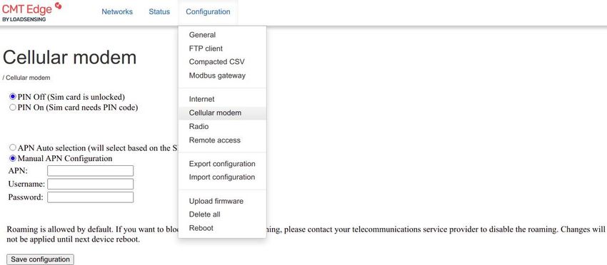
V1.0 May 2021

Gateway models
As well as with the previous gateway model, 3 different gateway versions are available, for different
geographical areas. Each country/area defines a specific regulation for the radio to be used, which may vary
in the used frequencies and other features.

Each gateway version is optimized to use a specific range of frequencies. As countries or areas define the
frequencies to be used, available radio models may be shared by different gateway versions.

868 GATEWAY

This gateway is optimized to work in frequencies around 868 MHz (863-874.4MHz). Initially designed for the
European region. Two models available:

    ●   CMT Edge model
    ●   CMT Cloud model

915 GATEWAY

This gateway is optimized to work in frequencies around 915 MHz (902-928MHz). Initially designed for the
North American region. Two models available:

    ● CMT Edge model
    ● CMT Cloud model
    ●
923 GATEWAY

This gateway is optimized to work in frequencies around 923 MHz (915-928MHz). Initially designed for the
Asian region, but due to local regulations related to radio settings, also available for the LATAM area, as
some CMT Edge radio configurations for this area are deployed on it. Two models available:

    ●   CMT Edge model
    ●   CMT Cloud model

3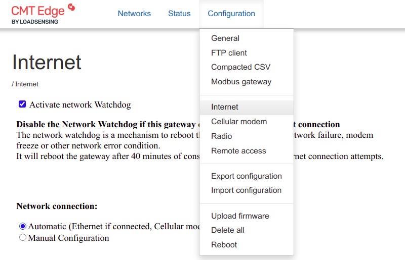
V1.0 May 2021

Gateway specifications
Equipment
The WI-SOS 480 rugged 4G Gateway is shipped with the following accessories:
    ● Gateway with internal antenna
    ● Installation plate with fixing bolt
    ● Grounding cable
    ● Ethernet cable gland and other interfaces covers and caps.
    ● PoE injector + Mains cable
    ● USB type C to Ethernet adapter (for local connection)
    ● External antenna adapter and vulcanized tape

Documentation:

    ●   Gateway information sheet (access credentials and radio settings for Edge version)
    ●   Gateway acceptance test document
    ●   Quick Start Guide

Not provided:

    ●   Metallic flanges or bolts for fixing the plate to a wall/pole
    ●   Tools required for mounting the device
    ●   Ethernet cables
    ●   SIM Card
    ●   External omnidirectional antenna kit (available under request)
    ●   PoE and external antenna surge protection (available under request)
    ●   Other peripheral devices

4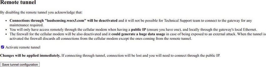
V1.0 May 2021

Gateway detail

    1.   RJ-45 Ethernet connector (with specific provided cable-gland)
    2.   Reset Button & Status lLEDs
    3.   USB-C connector (local interface)
    4.   SIM card slot (Mini Sim)
    5.   External Antenna connector (N) (antenna adapter required in case of using an external antenna)
    6.   Earthing cable
    7.   Waterproof air vent valve
    8.   Template fixing bolts
    9.   Internal antenna

5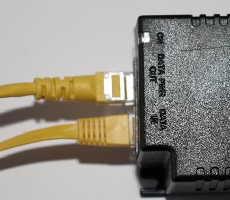
V1.0 May 2021

Specifications and ratings

The WI-SOS 480 rugged 4G gateway is made of Aluminium Alloy (case) with a high-impact resistant
polycarbonate cover, engineered to withstand harsh industrial and outdoor environments.

Flammability rating (UL94-V0), as well as good UV and chemical resistance
Impact resistance rate: IK07 (for the cover)
Ingress protection rate: IP67
Temperature: It may operate in an industrial temperature range, between -40°C and +60°C.
Altitude max. < 2000m / hygrometry 95% non-condensing
Dimensions: 265 x 165 x 100 mm (without external LoRa
antenna)
Weight: 1,4kg (mounting kit included)

6
V1.0 May 2021

Power consumption

The WI-SOS 480 4G Rugged gateway is powered by the Ethernet port. It requires being powered according to
the IEEE 802.3af Power over Ethernet protocol.
This means that the device must be powered using a PoE injector, provided by Worldsensing with the device.
If the PoE must be replaced, a new one can be requested to Worldsensing, or alternatively, acquire a new
one locally. This one must comply with IEEE 802.3af protocol.

The power consumption of the device has been tested in different scenarios to define different profiles
depending on the usage.
It has been tested powering the device to 50VDC (PoE injector uses a nominal 48 VDC voltage input, which
varies between 42 and 57 VDC), and tested with both Ethernet and mobile communications, with different
message load (2msg/min and 50 msg/min)

                      Supply Voltage    Current Avg.    Current Max.      Power Avg.      Power Max.

    Test 1 (ETH)           50V            0.086A           0.117A            4.3W            5.9W
    2 msgs/min

    Test 2 (GPRS)          50V            0.088A            0.16A            4.4W             8W
     2 msgs/min

    Test 3 (GPRS)          50V            0.096A           0.124A            4.8W            6.2W
    50 msgs/min

According to the tests, the device consumes a mean power consumption of 4.5 Watt (5 Watt to be on the
safe side). This means a 120 Wh daily consumption for a gateway working 24/7.

This information should be used to define any autonomous power system, such as solar panels, wind
turbines or any other external system.

Check the Annex “Solar power system used to power WI-SOS 480 4G gateways” available on the Knowledge
base for more information regarding external power sources.

https://worldsensing.zendesk.com/hc/en-us/articles/360017607599-LS-GW-G6-4G-USER-GUIDES

7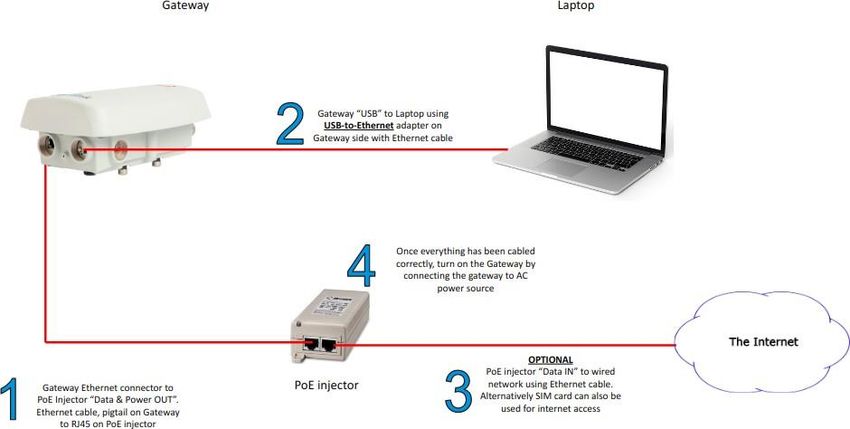
V1.0 May 2021

Communications

Internet access specifications
This gateway model allows two different ways to connect to the Internet: Using a SIM card or via Ethernet.

Ethernet:

The gateway has a built-in Ethernet port. A RJ45 cable can be directly connected to it to communicate with a
LAN network or the Internet.
This port is also used to power the gateway. This means a 48VDC PoE is required to power the gateway,
which can also provide Ethernet connectivity to the device, or use it just for powering the device and use the
Mobile connectivity for Internet connection.
The gateway is compliant with PoE IEEE 802.3af standard. This means the PoE injector (provided with the
device) should meet this specification.
The ethernet connection allows connecting the device to other devices such as External Mobile routers and
modems, Wi-Fi access points and any other devices with an Ethernet input, extending the range of
communications methods to comply with the project requirements.

Mobile connectivity:

Using a SIM card the gateway can be connected to the Internet all around the world, thanks to a 4G
Worldwide module with 3G/2G fallback.
The gateway uses the SIM card on its MINI-SIM format. A plastic adapter may be used to fit a nano/micro SIM
card into the mini SIM card slot.
The system is ready to connect easily (plug&play) a SIM card from any operator thanks to an internal APN
database with most of the APN settings of the most relevant carriers all around the world, as well as the
possibility of using the SIM card without PIN number.
APN settings, and the PIN number set on the SIM card can be set on the gateway by accessing locally if
required.

Note: Some Internet service providers (ISP) require the device being certified by them to make them work
with their SIM cards. This is the specific case of Verizon. WI-SOS 480 4G Rugged gateway is not yet certified,
so Verizon SIM cards may not work with this device. Worldsensing recommends using a different provider to
ensure Internet connectivity. For more information please contact our support team at
https://worldsensing.com/support

8
V1.0 May 2021

This table shows the frequency bands the gateway is able to use for each technology (4G, with 3G and 2G
fallback)

    LTE                            Band 1 (2100)                      LTE FDD:
                                   Band 2 (1900 PCS)                  - Max 150Mbps (DL)
                                   Band 3 (1800+)                     - Max 50Mbps (UL)
                                   Band 4 (1700/2100 AWS-1)
                                   Band 5 (850)                       LTE TDD:
                                   Band 7 (2600)                      - Max 130Mbps (DL)
                                   Band 8 (900)                       - Max 35Mbps (UL)
                                   Band 12 (700 ac)
                                   Band 13 (700 c)
                                   Band 18 (800 lower)
                                   Band 19 (800 upper)
                                   Band 20 (800 DD)
                                   Band 25 (1900+)
                                   Band 26 (850+)
                                   Band 28 (700 APT)
                                   Band 38 (TD 2600)
                                   Band 39 (TD 1900+)
                                   Band 40 (TD 2300)
                                   Band 41 (TD 2600+

    WCDMA                          Band 1 (2100)                      DC-HSDPA: Max 42Mbps
                                   Band 2 (1900 PCS)                  (DL) HSUPA: Max 5.7Mbps
                                   Band 4 (1700/2100 AWS-1)           (UL) WCDMA:
                                   Band 5 (850)                       - Max 384Mbps (DL)
                                   Band 6 (850 Japan)                 - Max 384Mbps (UL)
                                   Band 8 (900)
                                   Band 19 (800 upper)

    GSM                            B2 (1900 PCS)                      EDGE:
                                   B3 (1800 dcs)                      - Max 296Mbps (DL)
                                   B5 (850)                           - Max 236.8Mbps (UL)
                                   B8 (900)
                                                                      GPRS:
                                                                      - Max 107Mbps (DL)
                                                                      - Max 85.6Mbps (UL)

9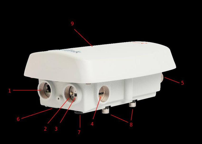
V1.0 May 2021

Radio specifications

WI-SOS 480 Rugged 4G Gateway may work with both WI-SOS 480 LoRa (CMT Edge) or WI-SOS 480 LoRaWAN
(CMT Cloud) networks. The type of available radios varies depending on the Gateway model and firmware
version selected.
More radio types may be deployed under request, if the existing ones do not fit with the local regulations for
a specific project, to be uploaded to the gateway using the firmware upgrade feature.

868 GATEWAY

This gateway is optimized to work in frequencies around 868 MHz (863-874.4MHz). Initially designed for the
European region, it supports these radio models:

LS-G6-KIO-EU for CMT Edge

     ●   868EU, designed for Europe according to ETSI regulations
     ●   866I radios, specifically designed to be used at India

LS-M6-KIO-EU for CMT CLoud

     ●   868EU, designed for Europe according to ETSI regulations

915 GATEWAY

This gateway is optimized to work in frequencies around 915 MHz (902-928MHz). Initially designed for the
American region, it supports these radio models:

LS-G6-KIO-915 for CMT Edge

     ●   FCC to be used at USA & Canada, according to FCC regulations (8 channel groups available)

LS-M6-KIO-915 for CMT CLoud

     ●   FCC to be used at USA & Canada, according to FCC regulations

10
V1.0 May 2021
923 GATEWAY
This gateway is optimized to work in frequencies around 923 MHz (915-928MHz). Initially designed for the
Asian region, it supports these radio models:
LS-G6-KIO-923 for CMT Edge
● 923A to be used at Australia
● 922S to be used at Singapore
● 922K to be used at Korea
● 923M to be used at Malaysia (2 channel groups available)
● 923P to be used at Peru
● 926C to be used at Chile
● 922B to be used at Brazil (8 channel groups available)
● 923T to be used at Taiwan (2 channel groups available)
LS-M6-KIO-923 for CMT CLoud
● 923A to be used at Australia, Brazil and Chile.
● 922S to be used at Singapore
The gateway is ready to work without setting any antenna as it already has an internal embedded one, which
permits a maximum of 2.1 dBi.
Anyway, an external antenna can be installed to provide a better radio coverage, as long as they comply with
the local radio regulations.
The internal antenna may provide a coverage near 75%-90% of the coverage an external antenna can
provide, if the gateway aims to the nodes (it is not an omnidirectional internal antenna) according to the
tests realized by Worldsensing.
It is recommended using an external antenna for those installations where nodes surround the gateway from
all directions, and those projects where distance from node to gateway is higher than 2 Km (wide area to
cover by a gateway). Also for linear projects where the gateway is not installed at one of the ends of the
sensor line.
These antennas and antenna kits bypass the internal ones (using the antenna adapter provided with the
gateway), and are provided by Worldsensing under request:
● LS-ACC-ANTGW-01 Vertical omni-directional outdoor antenna, 3 dBi, 868 MHz, 30 cm length.
Direct connection on the 4G rugged gateway.
● LS-ACC-ANTGW-03 Vertical omni-directional outdoor antenna, 3 dBi, 915/923 MHz, 30 cm
length. Direct connection on the 4G rugged gateway.
11V1.0 May 2021
● LS-ACC-SUPGW-01 Vertical omni-directional outdoor antenna kit, 3 dBi, 868 MHz, 30 cm length.
Antenna + 1m cable + support included.
● LS-ACC-SUPGW-03 Vertical omni-directional outdoor antenna kit, 3 dBi, 915/923 MHz, 30 cm
length. Antenna + 1m cable + support included.
● LS-ACC-SUPGW-02 Vertical omni-directional outdoor antenna kit, 6dBi, 915/923 MHz, 110 cm
length. Antenna + 1m cable + support included
Note: LS-ACC-ANTGW-01 and LS-ACC-ANTGW-03 are equipped with a N-male connector to allow the direct
connection on the 4G gateway (using the antenna adapter provided with the gateway).
12V1.0 May 2021 Embedded software The Rugged 4G Gateway has a different software depending on the model, CMT Edge or Cloud. CMT Cloud version has a basic piece of software -it could also be called firmware- which will allow configuring the Internet connectivity and WI-SOS 480 network connection. On the other side, CMT Edge version, contains a more complex software, as it stores data locally. This piece of software allows network configuration, Data storage on CSV Files, engineering units configuration, different Data output methods to connect WI-SOS 480 CMT Edge with third party monitoring software platforms, etc… In both cases, this software allows accessing the gateway in different interfaces; A local interface for initial setup and troubleshooting purposes, and the normal Internet connection interface, both via IP address (useful for Local area environments) or bridging the access through Worldsensing platform, via https://WI- SOS 480.wocs3.com/GATEWAY_ID, specially useful for accessing Internet connected gateways, specially when this connection is done via SIM card. Specific documents are available on our knowledge base which explains this software in detail, available at https://worldsensing.com/support, for both CMT Edge and CMT Cloud systems. The CMT Edge software embedded in the WI-SOS 480 rugged 4G gateway can be manually upgraded without Internet connection requirement when new developments are published. This is done by upgrading the gateway using a specific firmware upgrade file provided by Worldsensing. For more information please refer to the Gateway upgrade paragraph. Worldsensing support department strongly recommends subscribing to our mail list to be informed about the new updates and developments at https://info.worldsensing.com/subscribe_WI-SOS 480_maillist 13
V1.0 May 2021

Gateway deployment
Gateway deployment procedure
We recommend setting up and configuring the gateway in an office environment rather than going through
the startup procedure in an outdoor or industrial environment.
The gateway connection for the initial deployment requires these 4 steps:

Step 1: Connect the gateway to the PoE injector (Data & Power Out port)
Step 2: Connect the gateway to a laptop through the USB-C port using the provided USB-C adapter.
Step 3: Connect the gateway to the Internet. Two options available:
    - Wired mode: Adding an Ethernet cable from the Data IN port of the PoE to the network
    - Wireless mode: Inserting a Mini SIM card on the SIM slot
Step 4: Power on the gateway, connecting the PoE injector to mains. Gateway will completely boot when the
green status led is fixed, once the red blinking led (booting process) stops .

When the device is powered, it will start the booting process and try to connect automatically; Initially it will
try to connect to the Internet via Wired interface (using DHCP). If not possible (no wired connection, etc…)
will try to connect using the SIM card, using one of the predefined APN settings, and ignoring any PIN
number on the sim card.

14
V1.0 May 2021 In case of not connecting to the Internet, the gateway will remain disconnected, and local interface will be required to access the gateway locally and configure it accordingly Powering the Gateway The gateway has a unique input port to be powered; the Ethernet port. This port allows powering the device using an Ethernet cable with an RJ-45 connector. Different alternatives can be used to power the rugged 4G gateway, depending on the deployment of the gateway in the specific project. AC Source: PoE injector To power the gateway using this method, a standard Ethernet cable with RJ45 connectors must be connected to the gateway on one side, and to the DATA & Power OUT port of the PoE injector. Using a PoE injector is the most common way to power the device. Is the best option to power the gateway in those projects where a stable mains source is available near the gateway location, and when a wired Internet connection is required, as this device is able to provide both power and connectivity. A PoE injector is provided with every WI-SOS 480 rugged 4G gateway. Alternatively, any PoE injector available on the market can be used, if it complies with IEEE 802.3 af standard. The PoE injector must provide an output power between 44 and 57VDC voltage (48VDC nominal output voltage). PoE switches and other networking devices can also be used. Worldsensing recommends using the provided PoE injector, as it has been tested and complies with all the requirements of the gateway. The length of this cable can be up to 100 meter long; this allows installing the gateway in the top of a tower, pole etc… and installing the gateway in the basement to power it using mains . 15
V1.0 May 2021

The provided PoE injector is not rated to be used outdoors, in case of installing it outdoors, it should be
protected as required.

DC Source
The Loadsensig rugged 4G gateway can also be powered using a 42 to 57VDC input, using the same wiring;
the Ethernet RJ45 connector. The power supply must be isolated.
This method allows using a customized power supply, using a DIN Rail RJ45 to terminal block adapter for the
power output.

Solar panel
In case of using a standalone power system, such like solar panels, a specific device (charge controller) should
be used to provide the required output voltage (42 to 57 VDC) with the correct terminal (RJ45 male
connector)
Worldsensing recommends using the LS-ACC-SC1248 device, designed to manage the solar panel + battery
kit, and gives a PoE output to power the device. It also has an alternative 12VDC output.

16
V1.0 May 2021

More information about powering the gateway using standalone systems (solar panels, wind turbines and
hybrid systems can be found at our knowledge base HERE.

Local access
The gateway is always ready to be accessible using the local interface, by connecting a laptop to the gateway
using the USB-C to Ethernet adapter.
This interface allows securely accessing the gateway if required for the initial deployment, internet
connectivity modifications or troubleshooting, when other interfaces are not available.

The steps to access the gateway are:

     -   Connect the USB-C to Ethernet adapter on the USB-C slot
     -   Connect an ethernet cable on the adapter side
     -   Connect the other side of the cable in the laptop
     -   Check the Ethernet interface of the computer is configured to receive an automatic IP address (DHCP
         mode)
     -   In case the gateway is not powered, power it and wait until it is booted (Green led ON, Red led OFF)
     -   Once the connection is available, open a web browser and access to:
                  https://169.254.0.1
     -   A self-signed security certificate must be accepted to access the gateway
     -   Introduce the admin credentials provided by Worldsensing (Available on the Gateway Information
         Sheet)

17
V1.0 May 2021
Network configuration
The gateway is pre-configured in automatic mode to make it communicate with the Internet as soon as it is
powered and booted. This means, as soon as the gateway is booted, it will follow these steps automatically
to connect to a network/Internet:
1. Checks if there is connectivity on the Ethernet port. If exists, will try to connect to the Ethernet via
Ethernet looking for a dynamic IP address receiving it via DHCP.
Note: Connectivity on this interface means the gateway is connected to a managed network via
Ethernet or to an external networking device, such as an external modem, satellite modem.. In case
of powering the Gateway using PoE injector it will require a second cable connected from the Data In
port of the PoE to the network
2. If this connectivity does not exist or fails, the gateway will switch to the SIM card interface. If it exists
(a SIM card is inserted on the miniSIM slot), it will try to connect to the mobile network using one of
the APN settings preconfigured on the gateways internal database, and using no PIN Number.
3. If both systems fail, the gateway will remain disconnected, working on standalone mode (Radio only),
and will require local access for the initial deployment.
In any case, it is strongly recommended selecting the appropriate interface during the initial setup. This is
done on the CONFIGURATION / INTERNET Tab for the LS CMT Edge Gateway, and in the INTERNET
CONFIGURATION tab for LS CMT Cloud Gateway. This configuration may avoid any connectivity issues in case
of reboot.
18V1.0 May 2021
Ethernet interface connection
Ethernet configuration allows connecting the gateway using a wired interface. It will require connecting a
cable from the DATA IN port of the PoE injector to the wired managed network, or device which will provide
the LAN/WAN connectivity ( external router, etc…)
When setting the Manual configuration, two different Ethernet options can be selected:
Ethernet with DHCP, where the gateway receives a dynamic IP address from a DHCP server installed on the
network. This is the most common configuration for a gateway connected to a managed network, as usually
all those networks, routers, etc… have a DHCP server already configured.
Ethernet with static IP: This mode is selected when a fixed and known IP address must be set. It may be
required if some ports have to be open on the firewall to allow the gateway access to the internet. Also if it
works in a LAN network, but will act as a server where users will login to access the data.
In this case it is necessary to know all the networking parameters, usually provided by the IT team:
- IP address
- Subnet mask
- Default gateway
- DNS server address
“Save Configuration” button must be clicked to apply changes. A reboot is required to apply changes.
Note: In case of configuring the gateway in a LAN environment, or having ICMP traffic blocked, the Network
watchdog should be disabled to avoid gateway reboots due to the trigger activated. Disabling the Remote
access should also be required to avoid the same behaviour, at CONFIGURATION / REMOTE ACCESS for edge
gateway. Bear in mind disabling the remote access will disable the firewall in case of using SIM card
connection, allowing incoming connections from any IP, which may increase the data consumption
19V1.0 May 2021 4G (SIM card interface) connection This mode will automatically try to connect the gateway using the SIM card inserted in the gateway. The gateway has a list of predefined APNs in the internal database, and is pre configured with the PIN number disabled; this means the gateway could connect using this interface without any configuration if the PIN number is disabled previously (a mobile phone is required for this step) and the used ISP is on the database. “Save Configuration” button must be clicked to apply changes once this interface is selected. A reboot may be required to apply changes. Alternatively, these parameters should be configured on the device to make it work correctly. This is done on the CELLULAR CONFIGURATION tab for the Cloud gateway, and on CONFIGURATION / CELLULAR MODEM on edge gateway. Save Configuration button must be clicked to apply changes. A reboot may be required to apply changes. NOTE: Roaming is enabled on the gateway to be compatible with global SIMs. Ask the ISP to disable it on the SIM card if not required, to avoid increasing the cost of the mobile connectivity. 20
V1.0 May 2021
Radio configuration
WI-SOS 480 rugged 4G Gateway is delivered with preconfigured radio settings, for both CMT Edge and CMT
Cloud solutions. This configuration may be modified according to the project requirements, such as:
- Gateway replacement
- Default radio does not comply with local regulations (Edge & Cloud)
- Default network services not associated with the project (Cloud)
The procedure of modifying this differs on both Edge and CLoud solutions.
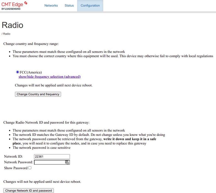
WI-SOS 480 CMT Edge
In the Edge configuration, a default radio model is preconfigured depending on the type of gateway model:
● Europe for 868 Gateway model
● FCC group0 for 915 Gateway model
● 923A for 923 Gateway model
Also, a default radio network is deployed. The network ID matches with the gateway ID, and the radio
password is the same one used for accessing the gateway with the admin user. This information is provided
by Wordsensing, and it can be found on the Gateway Information Sheet, which comes with the gateway.
These parameters can be modified if required at CONFIGURATION / RADIO tab, by selecting the appropriate
radio type at “Change country and frequency range”.
Contact worldsensing support team in case of any doubt selecting the appropriate network.
This radio type modification requires clicking the “Change country and frequency” button to be applied, but
does not require the gateway to be rebooted.
Also, the Network ID and password can be modified. This modification allows replacing a gateway by setting
the old gateway radio configuration. This way no edge device (data logger) handling is required to connect
the nodes again to the gateway.
This procedure requires clicking the “Change Network ID and password” button and rebooting the gateway.
21V1.0 May 2021 22
V1.0 May 2021
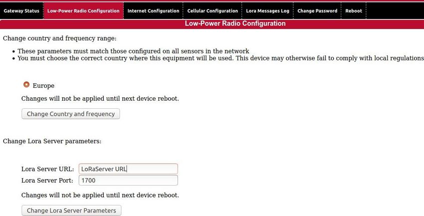
WI-SOS 480 CMT Cloud
WI-SOS 480 CMT Cloud solution is slightly different as no network is configured on the gateway. The CLoud
version of the gateway will redirect the incoming radio messages to a defined LoRa server deployed and
maintained by Worldsensing.
A default radio model is also pre configured depending on the type of gateway model:
● Europe for 868 Gateway model
● FCC group0 for 915 Gateway model
● 923A for 923 Gateway model
This parameter can be modified at Low-Power Radio Configuration tab, without need of rebooting the
gateway. It requires clicking the “Change Country and frequency” button.
The WI-SOS 480 network parameters can also be modified on the same tab. In case of being required,
Worldsensing will advise about the correct parameters.
Note: Modifying these parameters (both URL or Port) may provoke data not arriving to the data server. Do
not modify it unless requested by Worldsensing support team
23V1.0 May 2021
Remote access
All Internet connected WI-SOS 480 4G rugged gateway have a VPN connection to the WI-SOS 480 servers
platform. This connection creates a bridge connection which allows accessing the gateway from a known URL
instead of accessing through the IP address. It also allows performance telemetry monitoring for support
purposes by Worldsensing. The URL for each gateway varies on the gateway ID.
https://WI-SOS 480.wocs3.com/{GATEWAY_ID}
This VPN has an associated watchdog which triggers a reboot if the gateway is unable to establish the
connection with the servers, which may provoke periodical reboots and data acquisition loose while the
gateway is rebooting.
The user may prefer disabling this VPN on those gateways not connected to the Internet, or with the VPN
port firewalled.
The VPN is named as Remote Access on WI-SOS 480 gateways, and it can be disabled at CONFIGURATION /
REMOTE ACCESS tab on the gateways with CMT Edge firmware version. “The Activate remote tunnel” should
be unticked, and the “Save tunnel configuration” button clicked.
The same feature can be modified on the gateways with CMT Cloud firmware version at CHANGE PASSWORD
tab
Bear in mind that disabling the remote tunnel:
● Will only allow accessing in case of having a public IP address.
● In case of using a cellular connection (SIM card), no firewall settings will be applied. This means, any
data could access the gateway in case of external attack, provoking a significant increase in data
consumption if it happens. (The firewall is disabled for Ethernet connections, as the security should
be provided by the network where it is connected).
Worldsensing recommends leaving it enabled unless those cases where the gateway is not Internet
connected.
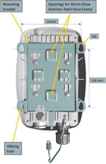
24V1.0 May 2021 Gateway installation WI-SOS 480 rugged 4G Gateway has been designed to be easy to install and deploy on the field. A unique template is provided together with the gateway, which allows a fast mounting and unmounting of the device. This template allows installing the gateway in a wall, by locking it using four 6mm screws to the oblong holes, and also installing it in a pole, by locking it using stainless steel hose clamps in the two central openings. These Hose Clamps width should not exceed 14mm. Once the template is firmly fixed, the gateway can be installed on it by using the 4 fixed round bolts of the back of the gateway on the template holes, and moving it downwards until they get locked. Once the gateway has been presented to the template, it can be locked to it by screwing the security screw in the lowest part of the template. Note: Check the earthing cable has been fixed to the earthing screw on the back of the gateway before presenting the gateway. 25
V1.0 May 2021

     This template is designed to support the gateway
     only. In case of using an external antenna instead
     of the internal antenna, the specific mounting kit
     shall be used.

     The antenna mounting is provided together with
     the low loss cable and the external antenna itself,
     when requesting one of the external antenna kits.
     (More information about these kits on the Radio
     specifications paragraph.

     In case of using an External antenna, the antenna
     N adapter should be connected to the gateway to
     ensure a correct connection, and avoid signal loss.
     This adapter can be connected to the antenna
     cable or to the external antenna directly, and
     protected with vulcanized tape, provided with the
     adapter, as displayed in the image below.

     Note: Make sure to screw the N adapter provided
     by Worldsensing into each gateway before
     installing the antenna. This adapter ensures a
     controlled pin length of the N connector and
     prevents any damage to the product.
     The use of this N adapter is mandatory to ensure
     the proper radio coverage.

26
V1.0 May 2021
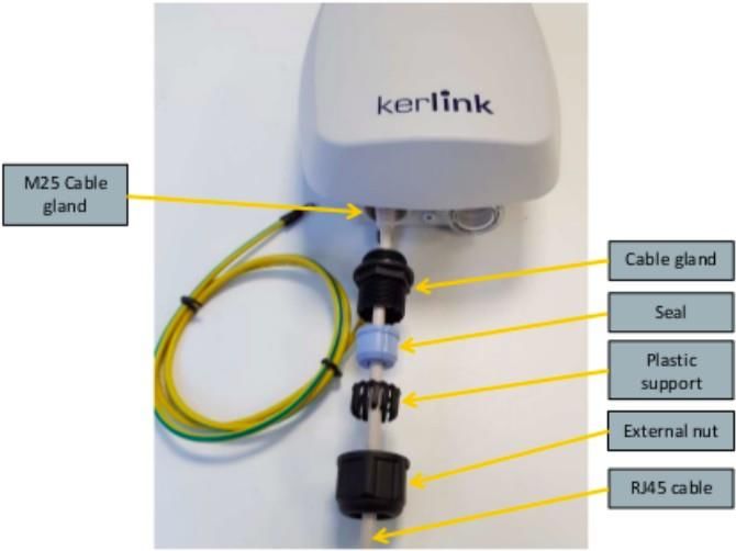
The gateway comes with a specific cable gland for
the Ethernet cable.
This cable gland will ensure a proper closing for
the Ethernet interface, so the gateway can be
deployed outdoors. This cable gland is required to
ensure the protection level of the device: IP67.
This scheme displays how the different parts of
the cable gland must be installed:
1) Pass the external nut and plastic support
for the seal through the Ethernet cable
2) Put the 2 parts of the seal (blue piece)
rounding the cable and fix it with the
plastic support
3) Pass the cable gland through the Ethernet
cable
4) Firmly connect the cable gland to the
gateway, and tighten the external nut to
it, covering the seal with it.
Once the gateway is installed and deployed it is necessary to close and tighten the two round covers for the
USB-C and SIM Card interfaces; The transparent one for the USB-C connector and Status leds, and the black
one for the SIM Card slot. The SIM Card cover may be tightened with a flat screwdriver while the USB-C one
requires using a wrench. Both covers have a 25mm diameter.
27V1.0 May 2021
Finally, it is strongly recommended wiring the gateway to earth to ensure lighting immunity and electrical
security.
Some installation recommendations:
● The gateway should not be installed on metallic walls to ensure a good radio performance.
● Installing the gateway in a higher position than the nodes is recommended as a good practise, being
at least 2 meter high.
● PoE injector, or any other peripheral device should be protected as required if installed outdoors.
● The internal antenna of the gateway is not omnidirectional; This means the gateway should aim to
the installed nodes in order to maximize the radio signal.
● The antenna mounting kit should be used to ensure the antenna is separated, at least, 15 cm from
any metallic surface, which may provoke a poor radio signal reception.
● The external antenna should be installed in a vertical position, with the provided low loss cable.
28V1.0 May 2021 Gateway upgrade For the CMT Edge Gateways, new firmware versions may have new features as well as bug fixes. It is therefore advisable to have the Gateway in an updated version to avoid possible problems or incompatibilities that have already been solved. To check the current version of the Gateway you need to access it locally or remotely and go to the STATUS > GATEWAY STATUS tab. On the General info section, the Firmware version can be found. WI-SOS 480 rugged 4G gateway initial version is 2.4.1. This version can be self-upgraded locally (no Internet access required) by using an OTA file, available for download on Worldsensing Knowledge base HERE. This upgrade process is done through CONFIGURATION > UPLOAD FIRMWARE option, where the appropriate OTA file must be loaded to go from the current version to the next one. Updates must be done version by version. The process will launch an error in case of not using a valid upgrade file, leaving the previous one loaded. This procedure is fully explained in an annex file available on our knowledge base. Note: A power cut during this process may leave the gateway unusable. Make sure the gateway is connected to a reliable power source. 29
V1.0 May 2021

F.A.Q. & Troubleshooting
Which Ethernet cable should be used to connect the gateway when it is installed Outdoors?
   - A shielded ethernet cable is recommended; STP or SSTP, with UV protection and designed for
       outdoor use (polyethylene external jacket). The diameter of the cable should be between 6.6mm and
       8.8 mm to fit with the Ethernet cable gland.
   - Ethernet Category 6 (Cat6) is recommended, specially if using long distances (maximum 100 meter)

Issues trying to access the gateway using the local interface:
    - Check the USB-Ethernet adapter and the Ethernet cable to the laptop are correctly connected and
         not damaged
    - Check the USB-Ethernet adapter used is the one provided by Worldsensing; Not all adapters in the
         market are compatible as not all of them use compatible drivers.
    - Check the gateway has correctly booted; This can be checked through the leds: The red led next to
         the USB-C interface will blink during the firmware boot, and gateway will be accessible once it stops
         blinking and only the green led is fixed.
    - Check if the Gateway has provided a valid IP address to the Ethernet interface of the computer; An IP
         on the range of 169.254.0.0/16 network should be received
    - Check if the gateway IP address answers to a PING message from a command line interface by
         launching a ping command to it. [ping 169.254.0.1]
    - Disable any other network interface, or firewall / antivirus software which may be blocking this
         connection.

Gateway does not connect to the internet automatically
   - Check all the steps of the deployment have been correctly completed. Specially check all the cabling
      has been correctly done before powering the gateway. Otherwise the gateway may have booted
      without being connected to a network / SIM card installed
   - Reboot the gateway by pushing the reset button for few seconds, or alternatively disconnecting the
      PoE injector from the gateway for few minutes (the gateway requires some minutes to completely
      shutdown due to the internal battery)
   - In case of being Internet connected using a SIM card, make sure the SIM card may work on the
      gateway without APN settings, and check it has the PIN number disabled.
   - The gateway will self-reboot every 40 minutes due to the Network watchdog (enabled by default).
      Check if this self-reboot makes the device connect to the Internet.

The gateway is Internet connected but I have lost the admin credentials.
    - Contact the Worldsensing support department.

30
V1.0 May 2021
Certifications
LS-G6-KIO-GW-923 / LS-M6-KIO-GW-923 Models
Brazil: "Este equipamento não tem direito à proteção
contra interferência prejudicial e não pode
causar interferência em sistemas
devidamente autorizados".
Singapore
Suppliers Declaration of Conformity COmplies with:
IDMA TS SRD
IDMA TS CMT
Indonesia
Ministry of communications and information NOMOR : 66489/SDPPI/2020
technology
LS-G6-KIO-GW-868 / LS-M6-KIO-GW-868 Models
Europe: Declaration of Conformity
Mozambique: Certificado de Homologação
Nº: 25/R/PAD/2020
31V1.0 May 2021 LS-G6-KIO-GW-915 / LS-M6-KIO-GW-915 Models USA: 2AFYS-KLK915LOI Canada: Technical acceptance certificate IC: 20637-KLK915LOI Contact Worldsensing Customer Success department for more information about these and other regions. 32
You can also read