PD ALARM TOOL FOR ONLINE DETECTION OF PARTIAL DISCHARGES IN MEDIUM VOLTAGE ACCESSORIES: TECHNOLOGY AND CASE STUDIES
←
→
Page content transcription
If your browser does not render page correctly, please read the page content below
PD ALARM TOOL FOR ONLINE DETECTION OF PARTIAL DISCHARGES IN
 MEDIUM VOLTAGE ACCESSORIES: TECHNOLOGY AND CASE STUDIES

         Lionel Reynaud1, Michel Trépanier2, Daniel Pineau1, Martin Charette1
            1 Hydro-Quebec Research Center, 2 Hydro Quebec Distribution

ABSTRACT
PD Alarm is a device that offers a quick and safe method of detecting and locating partial discharges (PDs).
The PD Alarm device (Figure 1) includes two antennas that pick up the signals, an acquisition module, a
processor, and a module to produce an alarm after detecting a partial discharge. The method includes the
detection of two magnetic fields with the two sensors, the digitization of the two received signals, the
processing of the two signals and the generation of a signal resulting from the processing. The processor
is configured to issue alarm instructions if the resulting signal has a property representative of a partial
discharge and remain in a standby state otherwise (ready for signal detection).
PD Alarm is able to detect the inversion of polarity of a PD produced between the two antennas at a range
of operation below 30 MHz and centered around 18 MHz [1]. This low band frequency allows a much more
standard and cheaper electronics for all necessary treatments than at higher frequencies. The development
of antennas is also one of the keys to success.

                               PD Alarm Device with its Two Antennas
                                             Figure 1

INTRODUCTION
Hydro-Quebec is a major producer, carrier and electricity distributor with more than 3,800,000 customers.
Some power outages occurring in the underground medium voltage distribution grid are caused by partial
discharges (PD) occurring in electrical equipment or accessories. Partial discharges may be due to a
problem in the materials during manufacture, to the degradation of the electrical insulation or to a mounting

                   ©2020 Doble Engineering Company — 87th International Conference of Doble Clients
                                                 All Rights Reserved
                                                         A-1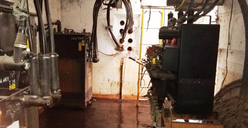
error of these equipment or electrical accessories. In addition to power outages, the presence of partial
discharges can also be associated with safety issues for workers doing maintenance or repairs on the
network.
With more than 12,000 km of medium voltage underground distribution lines and more than 600,000
accessories that can include PDs with potential for failure, Hydro-Quebec Distribution (HQD) has been
inspecting its underground network components using thermography and PD detection for more than 20
years. This represents an annual inspection of more than 100,000 accessories in 11,000 manholes.
Approximately 500 anomalies are detected each year by thermography and 100 anomalies by detection of
PDs.
Hydro-Quebec's preventive maintenance program by thermography and PD detection makes it possible to
target any potential anomaly of an accessory before a failure in service occurs. It also provides workers
with safe access to underground facilities. Each of the manholes inspected without any anomaly is given a
validity period of access of one year. But along with these inspections, several hundred repairs a year must
be made in invalid manholes requiring an emergency inspection.

HYDRO-QUEBEC’S INSPECTION PROGRAM
Through an inspection program, Hydro-Quebec performs preventive maintenance and ensures safe
access to underground structures. This inspection program has 3 components:
    1. Perform the thermographic inspection of the structure.
    2. Validate that each accessory has no partial discharges.
    3. Make a 360 image of the interior of the structure.
The temperature and the heat pattern of each splice is measured and analyzed. We are looking for dielectric
losses, interfacial issues and overheating connections. Hydro-Quebec has developed a diagnostic software
to evaluate the performance of spliced connections (Figure 2). The internal temperature of each accessory
and the current for which the maximum temperature will be reached is evaluated based on splice type,
cable size, splice and ambient temperatures.
Partial discharge measurements are complementary to the thermographic inspection. If no anomaly is
detected by the thermography, PD measurement is done on all the medium voltage components present
inside the underground vault. When partial discharge signals are measured, the access to the manhole is
then not authorized.
We recently started taking 360-degree images so we could take a virtual tour of the underground facilities
using Google Earth to navigate and select the vault to look at. It allows an optimization of the preparation
of the works, the evaluation of the degradation of the vault and new routing of the lines with less visits on
the ground.

                                           Thermography Strategy
                                                 Figure 2
                 © 2020 Doble Engineering Company – 87th International Conference of Doble Clients
                                                  All Rights Reserved
                                                        2 of 21
CONVENTIONAL VS NON-CONVENTIONAL PD MEASUREMENT
A PD is a complex physical phenomena consisting of a localized electrical discharge caused by partial
breakdown of an insulation medium under the influence of the local electrical field stress [2].

                                    +V               Conductor
                                                     Insulation
                                                Cx
                                 Void
                                                Cy
                Cb
                                                Cz

                                    -V               Conductor

                            Possible Origins of a PD in an Accessory [4]
                                              Figure 3
According to IEC 60270 [3], conventional PD measurement is the measurement of the apparent charge of
the partial discharge using an electrical method. The apparent charge q of a PD pulse is that charge which,
if injected within a very short time between the terminals of the test object in a specified test circuit, would
give the same reading on the measuring instrument as the PD current pulse itself. The apparent charge is
usually expressed in picocoulombs (pC).
According to IEC 62478 [2], non-conventional PD measurement is a PD measurement where it is not
possible to uniquely calibrate the magnitude of the PD in terms of its apparent charge. Measurement is
done using electromagnetic (HF, VHF and UHF), acoustical, optical or chemical methods.
As the electromagnetic VHF and UHF methods can often be used to locate the PD source, has greater
immunity to disturbances such as noise and increases the probability of achieving reliable results,
Hydro-Quebec has chosen to use non-conventional methods for its PD measurements.

EVOLUTION OF PD INSPECTION AT HYDRO-QUEBEC
PD measurement techniques were introduced in 1996 at Hydro-Quebec in an exploratory manner without
any criteria to support this new type of inspection. Several market instruments have been tested and in
2001 Hydro-Quebec issued its first standard.
[2001-2006] Early Years Using the DDP-540
The criteria for measuring partial discharges were established with the device approved by the company at
that time, namely the model DDP-540 (Figure 4). The DDP-540 has good detection sensitivity but low noise
immunity transmitted by radiation or propagating along the cable. It was found that it was impossible to
                 © 2020 Doble Engineering Company – 87th International Conference of Doble Clients
                                                  All Rights Reserved
                                                         3 of 21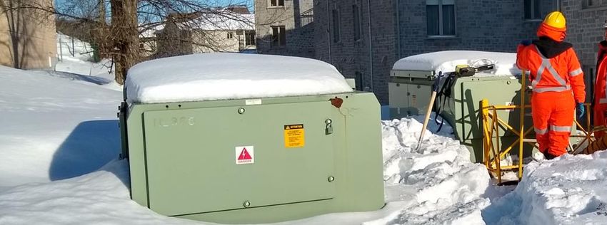
accurately determine if the measured PDs came from the accessory or the cables. It was also difficult at
times to interpret the measured value (dB).

                                                     DDP-540
                                                     Figure 4
[2007] Building a “Partial Discharge Analyzer” (PDA) for Experts
Following the issuance of this first standard, a mandate was given to the Hydro-Quebec Research Institute
to improve knowledge of PD measurements and to produce a device that is not influenced by signals
coming from outside of the accessory inspected. The research led to the realization of the Partial Discharge
Analyzer (PDA) system (Figure 5) [5] [6]. It was deployed in 2007 for use by Hydro-Quebec’s technical
support teams. The PDA system consists of two magnetic field sensors placed around the concentric
neutrals of the distribution cables and connected by a long cable to a computer permanently installed in a
truck. Diagnosis with PDA is not fully automatic and requires a final decision by an expert.

                        Partial Discharge Analyzer (PDA) for Expert Users
                                            Figure 5
                 © 2020 Doble Engineering Company – 87th International Conference of Doble Clients
                                                  All Rights Reserved
                                                        4 of 21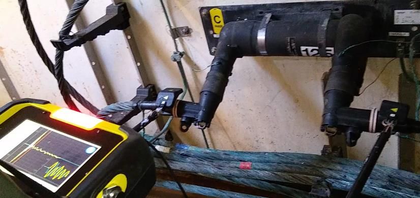
[2009] Deploying a PD Sniffer for Non-Expert Users
The total time elapsed between setup and diagnosis is a security issue when a worker stays in a manhole.
It appeared necessary to develop, alongside the PDA, a tool to automatically detect the potential presence
of PD in 20 seconds maximum per accessory. A PD “Sniffer” [7] [8] [9] using the same platform as the PDA,
but with the ability to recognize a PD signal in a fully automatic manner, was deployed in 2009. The PD
Sniffer has been designed for use by non-expert workers, in this case thermographers, as a first level safety
tool. Due to the design of PD Sniffer antennas, the system can only be used on non-shielded accessories
in which the neutral bypasses the accessory with a wire, as shown in Figure 6 and Figure 7.

                                The PD Sniffer Kit for Non-Expert Users
                                               Figure 6

                                                                  2 sensors

                           Using the PD Sniffer with One or Two Sensors
                                              Figure 7
                                                                  2 sensors
                                                                  measurements
[2020] Introducing a Lightweight PD Alarm Device
As previously mentioned, the PD Sniffer is used at the first level by teams of thermographers, while the
engineers use the PDA at the second level to confirm the presence of PDs. The PD Sniffer and the PDA
are accurate, but their purchase, operation and maintenance are expensive. In 2014, Hydro Quebec
decided to launch the development of the PD Alarm tool in order to realize a lightweight, fully portable,
easier-to-use PD detection device than the PD Sniffer, with the same efficiency as this one, but with a much
                 © 2020 Doble Engineering Company – 87th International Conference of Doble Clients
                                                  All Rights Reserved
                                                        5 of 21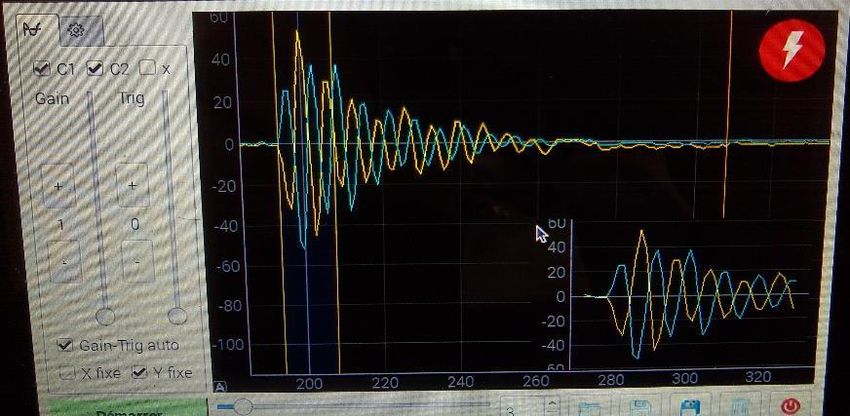
lower manufacturing cost. Another advantage of a simpler device would be to be used directly by the repair
teams to self-validate their access for a short period of time, without calling on the teams of thermographers.

                          PD Alarm Portable Device for Non-Expert Users
                                            Figure 8

GENERAL PRINCIPLE OF PD OPERATION ALARM
PD Alarm is in action as soon as it is turned on. This means that it captures and processes all the signals
received by its two antennas. It acts as a metal detector would do: an audible and light alarm is emitted as
soon as a PD is detected. It therefore allows the antennas to be moved slowly over the accessories.
The PD Alarm device is designed according to the principle of two antennas that are current loops capturing
the magnetic fields. The current generated in the current loops is transformed into voltage variation. A
microcomputer controls gain on amplification boards that amplify voltage signals from the antennas. The
gain is programmable from 20V/V to 640V/V in 5 scales.
The amplified signals are sent to a converter board. The converter board has two channels, each channel
having two ADC circuits of 200Ms/s. A trigger circuit dedicated to one of the antennas detects the arrival of
a voltage level, the trigger level being determined by a command from the microcomputer.
When a trigger occurs, the microcomputer communicates with the converter board to receive the digitized
signals. The microcomputer then processes the data to interpret the measurement results and report any
PD. One of the main conditions for a PD to be declared is that the signals measured on the 2 antennas are
inverted, which means that the signal comes from between the 2 antennas.
A power circuit receives the power of a set of batteries and feeds all the circuits. Voltage levels of 5V and
3.3V are provided. It allows charging of batteries. It also allows the control of the microcomputer to power
or de-power the various circuits. It includes timers for stopping and starting the microcomputer.
Figure 9 and Figure 10 show the general operating principle of the PD Alarm device. More detailed parts
of the operation are described later in the article.

                 © 2020 Doble Engineering Company – 87th International Conference of Doble Clients
                                                  All Rights Reserved
                                                        6 of 21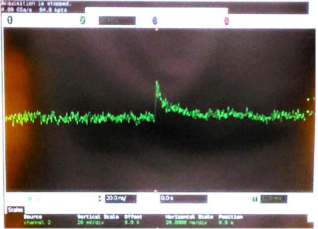
Diagram #1 of the Operating Principle of PD Alarm
                                            Figure 9
1.    A PD pulse occurs on an accessory in the power grid. It produces a current wave with harmonics
      from 1MHz to 1GHz.
2 et 3. This pulse from a few millivolts to some ten millivolts is detected by two current antennas, having a
       relatively narrow bandwidth and centered around 18MHz. The detected signals are amplified before
       being converted to digital values.
4.    Signals are displayed for visual inspection. If it turns out that the signals are inverted, it is probably a
      PD.
5.    In order to automate the detection, the product of the signals is displayed to highlight the inversion
      and to show their synchronization. Proper processing automatically detects and displays this
      condition and will raise an alarm.

                 © 2020 Doble Engineering Company – 87th International Conference of Doble Clients
                                                  All Rights Reserved
                                                        7 of 21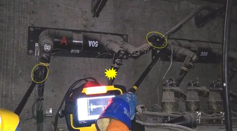
Diagram #2 of the Operating Principle of PD Alarm
                                           Figure 10

SETTING THE ANTENNA
The development of antennas has been a major challenge. Several antenna concepts were evaluated
before arriving at the selected final concept. All are based on the differential antenna principle, the objective
being to capture the PD signal between the 2 loops of the antennas and eliminate all the signals coming
from the outside.
One of the important characteristics of the magnetic field created by a partial discharge in a conductor is
that on both sides of the PD the magnetic fields are reversed (Figure 11).

                 © 2020 Doble Engineering Company – 87th International Conference of Doble Clients
                                                  All Rights Reserved
                                                        8 of 21
Magnetic Fields caused by a PD
                                                Figure 11
The basic idea of the PD Alarm device was to take advantage of the differential antenna that makes it
possible to cancel the signals at the antenna. Any magnetic field arriving at the antenna by a source other
than between the two loops produces no signal (all surrounding noise and PD from other sources are
canceled). Any magnetic field produced in the center of the antenna is detected and, since the antenna is
placed on an accessory, any signal above the noise level is considered as a PD in the accessory (Figure
12).

      Magnetic Fields of a PD coming from the Outside and the Inside of the Antenna
                                        Figure 12
Initial concept: 100 MHz Passive Broadband Differential Antenna
The first antenna (Figure 13) to be designed was a 100 MHz wideband passive differential antenna, the
cancellation of signals being done by the antenna without any electronic help.
The analysis of the frequency spectrum of a PD (Figure 14) picked up by this antenna led to the conclusion
that it was possible to operate at a much lower frequency band.

                         100 MHz Passive Broadband Differential Antenna
                                           Figure 13
The following picture is a typical PD signal measured with an oscilloscope probe with capacitive coupling
of 0.1pF (Figure 14). The transfer function of this type of measurement is flat over a very wide band. The
measured PD is close to reality.

                 © 2020 Doble Engineering Company – 87th International Conference of Doble Clients
                                                  All Rights Reserved
                                                        9 of 21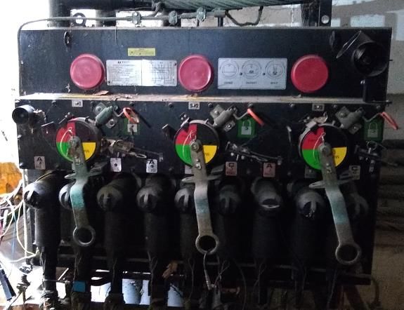
Actual PD Signal Measured at the Oscilloscope
                                           Figure 14
Frequency analysis (Figure 15) led to the development of an antenna operating at lower frequency and
narrow band.

                                       Frequency Analysis of a PD
                                               Figure 15
Evolution 1: Narrow Band 5MHz Passive Differential Antenna
The narrow band 5MHz differential antenna (Figure 16) improves the cancellation of undesired signals.
Since the antenna resonates at a particular frequency on a narrow band this helps to reduce the noise.

                © 2020 Doble Engineering Company – 87th International Conference of Doble Clients
                                                 All Rights Reserved
                                                       10 of 21
But the amplitude of the measured signals depends on the position of the antenna on the accessory, in
particular, the angle that it makes with the accessory, which makes analysis and decision-making more
difficult.
Differential Antenna at 5 MHz, Narrow Band
Figure 16
Evolution 2: Narrow Band 5MHz Passive Differential Antenna with Reference Loop
The solution was to add a reference measurement loop that allows the PD and noise signals to be compared
(Figure 17). The principle is as follows: when there is no PD, the amplitude of the signal measured on the
reference loop must be greater than that of the signal measured by the differential antenna, since on it the
signals cancel each other out; when there is a PD, the amplitude of the signal measured on the differential
antenna must be greater than the amplitude of the signal measured on the reference loop.
Differential Antenna at 5 MHz Narrowband and Reference Antenna
Figure 17
The reference loop unfortunately has an influence on the differential antenna because the loops have a
mutual inductance, which complicates the design.
Evolution 3: 10 MHz Narrowband Active Differential Antenna
To eliminate the unwanted influence effects of the reference loop, it was decided to cancel the signals with
an analog electronic circuit, and to migrate to a so-called active antenna (Figure 18). The two loops of the
differential antenna are now two independent loops which are amplified separately and added electronically.
The signal of the addition of the two loops is compared to the signal provided by each of the loops.
© 2020 Doble Engineering Company – 87th International Conference of Doble Clients
All Rights Reserved
11 of 21Antenna 10 MHz Narrow Band with 2 Independent Electronic Summation Loops
Figure 18
Despite the transition from the passive antenna to the active antenna, the comparison of the signals in a
purely analogue way in order to give a verdict of PD or non-PD proved to be complex.
However, with an antenna having a frequency band of a few MHz, the digital signal processing that could
not be done with a 100 MHz antenna now became easier and less expensive: the sampling frequency is
around 200 MHz rather than 1 GHz. It was therefore decided to perform all the signal processing digitally,
which makes it possible to add processing algorithms to make the diagnosis of PD or non-PD.
Final concept: Narrowband 18 MHz Digital Differential Antenna
The center frequency of the antennas should not be too low to maintain the amplitude and accuracy to
capture the signals on a short distance. Some tests validated that an antenna centered on 18MHz gave the
best compromise. In addition, despite the initial desire to achieve a compact differential antenna, the
accessibility of the accessories requires that the antennas be physically separated to be positioned
independently of each other (Figure 19), as with the PD Sniffer already used at Hydro-Quebec.
18 MHz Antennas with Digital Sampling and Processing
Figure 19
In the particular case of a joint, the wire used to make the continuity of the neutral causes a magnetic
disturbance which modifies the phase of the signals picked up by the antennas (Figure 20).
Joint with Derivative Neutral
Figure 20
© 2020 Doble Engineering Company – 87th International Conference of Doble Clients
All Rights Reserved
12 of 21To overcome this problem, the loop of each antenna has been designed so that it minimizes the influence
of the field produced by the neutral wire. It is formed of a central conductor surrounded by a conductive
sheath for rendering the central conductor substantially insensitive to an electric field. The loop is small in
size, to be tuned to the 18 MHz frequency, and has a ferrite that directs the magnetic field of the core to the
center of the loop (Figure 21). The ferrite forms an angle to follow the curvature of the accessories (joints,
fuses, bent plugs, etc.).
Diagram of the Loop of the 18 MHz Antenna
Figure 21
FIELD RESULTS
Preliminary Field Tests
PD Alarm was first tested extensively in a laboratory. But in order to validate its performance convincingly,
field tests were carried out in early 2019 in underground manholes of Hydro-Quebec's medium voltage
distribution network. The verdicts of the PD Alarm device were compared to those given by the PD Sniffer.
The presence or absence of PD was then confirmed by the engineers using the PDA. A total of 9 manholes
were visited and 167 components were tested.
Table 1
Field Results
Number of Number of
Manhole type
manholes components
Disconnecting
2 18
chamber
Manhole 4 55
Transformer vault 3 94
Total 9 167
On all 167 components, the PD Sniffer detected the presence of PD on 4 of them. PD Alarm detected the
presence of PD on only 2 of these 4 components (Figure 22).
After analysis with the PDA, the engineers confirmed the presence of PD on the 2 components identified
by PD Alarm and no PD on the others.
© 2020 Doble Engineering Company – 87th International Conference of Doble Clients
All Rights Reserved
13 of 21Field Comparative Results
Figure 22
Approval Tests
Approval tests began at the end of 2019 to validate PD alarm performance according to Hydro-Quebec’s
standards and procedures and before its deployment. Here are 2 examples of tests carried out in Quebec
City the 5th and the 6th of February 2020.
VISTA SWITCHGEAR
Tests were carried out on six submersible epoxy isolated fuses connected to two VISTA switchgears. Some
PDs were previously measured by a team of thermographers on one of the fuses (phase C of switchgear
#1). A team of experts made up of a technician and an engineer went to confirm this verdict.
PD Alarm Measurement on a Fuse Connected to a VISTA Switchgear
Figure 23
© 2020 Doble Engineering Company – 87th International Conference of Doble Clients
All Rights Reserved
14 of 21The PD alarm device was first used to check each of the 6 fuses. PDs were detected on 3 of them, including
the phase C fuse of switchgear #1. The expert team then confirmed that there were PDs on these 3 fuses
and absence of PD on the others.
PD Analyzer Signals (top) vs PD Alarm Signals (bottom)
Figure 24
As seen on Figure 24, the signal measured by the team of experts with the PD analyzer device and those
measured by the PD alarm device show two inverted signals. It is an indication that the PD comes from
between the 2 antennas, therefore from the accessory.
© 2020 Doble Engineering Company – 87th International Conference of Doble Clients
All Rights Reserved
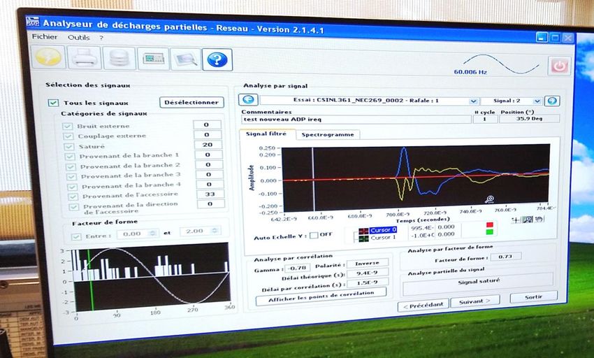
15 of 21T ELBOW ON A SWITCH
Tests were carried out on a switch inside a transformer manhole. Some PDs were previously measured by
the team of thermographers on the first T elbow to the left of the switch. PD alarm didn’t detect any PD and
this verdict was confirmed by the team of experts with the PD analyzer.
T Elbow on a Switch
Figure 25
The signals measured by the PD analyzer as seen on Figure 26 are in phase which means that the signals
don’t come from the T elbow under test.
Two PD signals in Phase Measured by the PD Analyzer
Figure 26
© 2020 Doble Engineering Company – 87th International Conference of Doble Clients
All Rights Reserved
16 of 21MANUFACTURING PROBLEMS CAUSE OF PARTIAL DISCHARGES
We have learned from experience that some partial discharges detected after the installation of a new
component in the network were caused by manufacturing problems. Here are some cases that we have
demonstrated through our tests and analyzes.
Disconnectable Cable Splice (capacitive plug)
Some molding problems can cause cavities in cable splices. Due to the cavities, PDs are generated when
the splice is energized. As soon as the problem is detected, the splice has to be replaced.
Disconnectable Cable Splice (Capacitive Plug)
Figure 27
T Elbow on Medium Voltage Switches
For T elbows, the connector must always be in contact with the semiconductor. The manufacturer has
performed post-production tests with a "test" connector of a different size from the real connector. Once
installed in the network the real connector does not make perfect contact with the semiconductor and PD
is generated.
T Elbow on Medium Voltage Switches
Figure 28
© 2020 Doble Engineering Company – 87th International Conference of Doble Clients
All Rights Reserved
17 of 21Molded Vacuum Switch
A bounding issue between the rod and the silicone diaphragm causes dust contamination and partial
discharges when energized.
Molded Vacuum Switch
Figure 29
Cap for Grounding Device
In this case, the factory test setup was not suited to detect a problem of bounding and porosity.
Cap for Grounding Device
Figure 30
© 2020 Doble Engineering Company – 87th International Conference of Doble Clients
All Rights Reserved
18 of 21Submersible Epoxy Isolated Fuse
Air gaps in the silicone filling generates PDs when the fuse is energized. We no longer install any of these
fuses, but we tolerate those already installed.
Submersible Epoxy Isolated Fuse
Figure 31
CONCLUSION
Over the years, PD measurement has allowed us to overcome several anomalies associated with the
manufacturing of electrical equipment. Even though manufacturers carry out tests, it sometimes happens
that the test methods do not detect all anomalies. PDs may also be due to a mounting error or the
degradation of the electrical insulation.
When problematic equipment is installed in a network, it can be expensive and complicated to replace,
even if the cost of each part can be very low. Since the beginning of Hydro-Quebec’s maintenance program,
the number of anomalies decreased and has stabilized in the underground network.
Evolution of the Number of Anomalies since Year 2000
Figure 32
On a representative sample of the underground network, PD Alarm responded perfectly and identified the
PDs without giving any false negatives. It is important to remind that PD Alarm can only be used on non-
shielded components. Its antennas and electronics based on a frequency band much lower than the tools
usually available making it an inexpensive first level device for non-experts, while remaining very effective.
Its use is extremely intuitive and allows to quickly locate a PD on an accessory.
And even if it is designed for non-expert users, a more experienced user can, by looking at the displayed
signals, confirm the verdict issued by the device. The relatively simple software processing, coded in Python
language under Linux and running on a Raspberry Pi, can easily evolve at low cost.
© 2020 Doble Engineering Company – 87th International Conference of Doble Clients
All Rights Reserved
19 of 21REFERENCES
[1] D. Pineau et al., 2019, “Détecteur de décharge partielle et méthode associée”, United State Patent
pending, CA 3,033,769
[2] IEC 62478 technical specification {ed1.0} (High voltage test techniques - Measurement of partial
discharges by electromagnetic and acoustic methods)
[3] IEC 60270 technical specification {ed3.1} (High-voltage test techniques - Partial discharge
measurements)
[4] https://en.wikipedia.org/wiki/Partial_discharge
[5] D. Fournier et al., 2005, “Detection, location and interpretation of partial discharges in the
underground network at Hydro-Quebec”, Acts of the CIRED Conference
[6] D. Fournier et al., 2012, Detection, “Localization and interpretation of partial discharge”, United
State Patent US 8,126,664
[7] F. Léonard et al., 2011, “Partial discharge (PD) sniffer for worker safety in underground vaults”,
Acts of the CIRED Conference
[8] L. Reynaud et al., 2011, “Partial discharge (PD) automatic diagnosis tool for worker safety in
underground vaults”, Acts of the Jicable’11 Conference
[9] F. Léonard, 2014, “Dynamic Clustering of transient Signals”, United State Patent Application
Publication, US 2014/0100821 A1
BIOGRAPHIES
Lionel Reynaud obtained a University Technological Diploma in Electrical Engineering and
Industrial Computering in 1989 and a Master's degree in Industrial Science at the Institute of
Sciences and Technology of St-Quentin in France in 1990. He completed later a Master in
Computer Systems at the Higher Institute of Aeronautics and Space in Toulouse in 1991. After
a few years as a consultant in the private sector, he became a researcher at the research
institute of Hydro-Quebec (IREQ) in 1998 and participates in the development of numerous
control and monitoring systems. Since 2003 Lionel Reynaud specializes in problems related to cables and
accessories of Hydro-Quebec's underground medium voltage distribution network. As a project manager,
he leaded the deployment of tools for fault location and partial discharges detection.
Michel Trepanier obtained his university degree in engineering with a specialty in electrical
energy and electrical networks from the École de Technologie Supérieure (ETS) of Montreal
in 2005. He has been working since 2006 at the underground distribution division for Hydro-
Quebec. He acted as technical support engineer for the inspection teams for predictive
maintenance, localization and analysis of underground faults. Since 2011, he joined the
underground distribution standards department. He specializes in thermal inspection, in
partial discharges analyzing and the characterization of medium voltage electrical accessories. He also
contributed to several expertise and innovation projects with the Hydro-Quebec research institute.
© 2020 Doble Engineering Company – 87th International Conference of Doble Clients
All Rights Reserved
20 of 21Daniel Pineau graduated in electrical engineering from the University of Quebec at Trois-
Rivières (UQTR) in 1990. He has been an engineer at the Hydro-Quebec research center
since 1992. He has since worked as an expert in electronic design and signal analysis and
processing on numerous innovation projects concerning the underground lines of the
distribution network, such as location of faults on underground cables and accessories and
partial discharges detection.
Martin Charette graduated in electrical engineering from École Polytechnique de Montréal in
1989. He has been a researcher at Hydro-Québec research center since 1990. He has
designed and developed several computer systems dedicated to the electrical distribution
network, such as those dedicated to the analysis of smart meter data, the location of faults
on underground cables and accessories and the detection of partial discharges.
© 2020 Doble Engineering Company – 87th International Conference of Doble Clients
All Rights Reserved
21 of 21You can also read