Investigating the Effect of Stepped Scarf Repair Ratio in Repaired CFRP Laminates under Compressive Loading - MDPI
←
→
Page content transcription
If your browser does not render page correctly, please read the page content below
Article
Investigating the Effect of Stepped Scarf Repair Ratio in
Repaired CFRP Laminates under Compressive Loading
Spyridon Psarras 1 , Theodoros Loutas 1 , Magdalini Papanaoum 1 ,
Orestis Konstantinos Triantopoulos 1 and Vasilis Kostopoulos 1,2, *
 1    Mechanics Laboratory, Department of Mechanical Engineering & Aeronautics, University of Patras,
      26504 Patras, Greece; spsarras@upatras.gr (S.P.); thloutas@upatras.gr (T.L.); papanaoumm@gmail.com (M.P.);
      iErnesto94@gmail.com (O.K.T.)
 2    Foundation of Research and Technology, Institute of Chemical Engineering Sciences (FORTH/ICE-HT),
      Stadiou Str., GR-26504 Patras, Greece
 *    Correspondence: kostopoulos@upatras.gr

 Received: 16 August 2020; Accepted: 13 October 2020; Published: 19 October 2020

 Abstract: In this work the effectiveness of stepped repairs to damaged fiber reinforced composite
 materials is investigated by using previously validated numerical models which were compared with
 tested repaired composite plates. Parametric studies were carried out in order to assess the scarf
 ratio (i.e., step length to ply thickness ratio) influence on ultimate forces, displacements, stresses and
 stiffnesses. FE models with repair scarf ratios varying from the value of 20 to the value 60 with a step
 increase of 10 were developed. The numerical models allowed a direct comparison of the influence
 that the scarf ratio had to the strength and stiffness restoration of the repaired composite structure.
 The study verifies that the restoration of the strength of a damaged laminate depends largely on the
 size of the repair patch. Generally, the bigger the size of a patch, the stronger the repaired structure is,
 up to a critical threshold size. To maximize the strength restoration, it is advised that the number of
 steps in each patch are no less than the number of plies on the base laminate.

 Keywords: scarf repair; numerical analysis; repair in composites; finite element

1. Introduction
      Fibre reinforced composite materials are increasingly used in many applications, mainly in
the aerospace industry, and the need of maintenance and repair is of main concern for both the
manufacturers and the end-users. Multi-layered composite structures are susceptible to shear and peel
stresses along the interface between the laminate. When damage occurs, a repair is needed in order to
stop the damage propagation and restore as much of the strength and stiffness as possible.
      It is proven that adhesively bonded repairs are more effective than bolted repairs in composite
materials, as they allow a more uniform load transfer without inducing stress concentrations [1].
Composite materials’ bonding has been extensively researched using numerical or experimental
models [2–6] with various joint configurations: uniform lap, stepped lap, scarf or stepped scarf. In the
latter, which is the focus of this work, the stepped scarf repair was studied, as this method is more
attractive to the aerospace industry. Also, scarf repairs are more efficient than lap repairs, because the
former have in general higher strength and can be used to bond thin, as well as thick adherends.
Depending on certain conditions, though, stepped scarf repairs are more easily applied. However,
they exhibit a higher stress concentration along the corners of each step [7].
      In the relevant literature, a few analytical approaches have been attempted regarding scarf repairs.
It has been proven that in stepped-scarf joints the stress distribution is non-uniform when dissimilar
adherends are bonded together. Lubkin was the first who studied the effect of the adherends’ stiffnesses

J. Compos. Sci. 2020, 4, 153; doi:10.3390/jcs4040153                                   www.mdpi.com/journal/jcs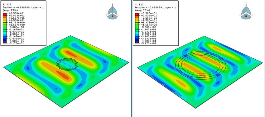
J. Compos. Sci. 2020, 4, 153                                                                          2 of 13

to the scarf angle. Nonetheless, the angles that he predicted were so big that they cannot be practically
applied in aerospace applications [8]. Moreover, a remarkable conclusion is that there is a stress
concentration at the edge of the more compliant adherend [9,10]. Later, Hart-Smith mathematically
analysed the stress distribution for stepped scarf repairs taking into account potential adherend stiffness
dissimilarity and thermal mismatch [11].
     An experimental research [12] evaluated how several parameters, namely type of material,
temperature, moisture and the scarf’s geometry influence the failure load. An important observation
from this study was that the increase of the scarf angle gradually decreases the ultimate load bearing
capacity. More specifically, it has been proven that only scarf angles less than 2◦ will result in the
laminate failing outside the repaired region [13]. However, these results have no practical interest,
as such extended patches are not applicable. Baker et al. [14] observed strain concertation in the
repair doubler plied above the top end of the scarf aluminium honeycomb sandwich beam specimens.
This conclusion was compatible with the FE models.
     Gunnion and Herszberg [15] conducted a parametric study using finite element models to
investigate the sensitivity of normal and shear stress distribution of scarf repaired laminates, subjected to
tensile loading, to joint performance parameters. They were mainly focused on the geometry’s
parameters, including the stacking sequence, the adhesive and laminate thickness, the scarf angle,
the number of over-plies and the effect of mismatched adherend lay-ups. One of their most relevant
conclusions was that the addition of an overply can dramatically decrease the peak stresses and that
the integrity of a repaired laminate is not sensitive to the patch’s lay-up. However, the analysis was
conducted in two-dimensional models and nonlinear behaviour was not considered for the adhesive.
Hence, stresses in the width direction were assumed to be constant [16].
     More recently, Bendemra et al. reached the same conclusion [17]. Another two-dimensional linear
analysis [18] has been carried out in five tensile loaded quasi- isotropic repaired plates with scarf angles
ranging from 1.1◦ to 9.2◦ to compare the shear stress distribution along the adhesive. Failure loads
were obtained using a number of different failure criteria each time. Kumar et al. [13] experimentally
investigated the failure modes of scarf repaired laminates in uniaxial tension with angles that were
varying from 0◦ to 5◦ . It was concluded that the plates with a scarf angle below 2◦ failed due to
fibre fracture, while those with a scarf angle above 2◦ failed due to shear stresses in the adhesive
between the repair patch and the laminate. These results came to agreement with the corresponding
three-dimensional linear elastic FE models. In this study the adhesive was assumed to be perfectly
bonded to the parent adherend. Tzetzis and Hogg [19] examined the tensile failure modes and failure
loads in vacuum-assisted resin infused repairs for three different scarf angles. A parametric stress
and failure numerical study was performed in two-dimensional repaired laminates with different
scarf angles and stacking sequences [20] by Campilho. In this non-linear analysis, cohesive damage
models were used in order to better simulate the behaviour between the adherent and the repair patch.
One of the findings was that the fracture properties of the adhesive do not influence the strength of the
repaired laminate, whereas the mechanical properties governed its behaviour. Campilho et al. [21] also
used cohesive damage models in order to predict the behaviour of CFRP plates under tensile loading.
The majority of the studies take into consideration only the cohesive interaction between the patch and
the parent laminate and not between the plies. Also, there is a limited number of studies that examined
stepped scarf repaired laminates that are subjected in compressive loading.
     In this investigation the effectiveness of stepped repair to damaged fibre reinforced composite
materials was investigated by using previously validated FE numerical models [22]. A parametric
study was conducted in order to evaluate the influence of the scarf ratio to the integrity of the repaired
laminate and the stiffness restoration of the laminate. Non-elastic behaviour was assumed for both the
repaired laminate and the adhesive between the laminate and the repair patch. Also, all numerical
models considered the shear stresses between the layers and the Hashin’s damage criteria were
used [23].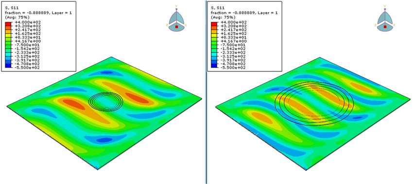
J. Compos. Sci. 2020, 4, 153                                                                                                3 of 13

2. Materials and Methods
     Abaqus CAE was used for the modelling of the laminate made of IMS 24K 997-2, taking into
account the actual strength (Hashin damage) with properties as listed in Table 1. Several parametric
numerical models with different scarf ratios were developed. The repaired laminate was analyzed
with and without sub laminates, taking into account the actual strength of each layer (Hashin damage).
The creation of the models was based on FE models of a previous study [22] where the FE models were
validated against three different types of tests; double lap shear tests, Compression After Impact (CAI)
standard tests and Stepped scarf repaired coupon tensile tests. This way the models were capable of
capturing the lamina behavior, the bonding strength and the patch performance. Parametric non-linear
analysis was performed, using 8-node continuum shell elements with a mesh size of 1 mm, that have
displacement degrees of freedom, resulting in models with one hundred and fifty thousand elements.
Also, FE models were created with different scarf ratios, varying from 20 to 240.

            Table 1. Laminates’ and repair patches’ mechanical and fracture properties (MPa and J/m2 ).

    Young’s Modulus 1          Young’s Modulus 2   Poisson Ratio 12     Shear Modulus 12   Shear Modulus 13           -
          137.500                    9.650                0.35                3.950              3.950                -
                                 Longitudinal                              Transverse
   Longitudinal Tensile                            Transverse Tensile                      Longitudinal Shear     Transverse
                                 Compressive                              Compressive
        Strength                                       Strength                                Strength         Shear Strength
                                   Strength                                 Strength
          896.72                     518.1                33                  101                40.13              40.13
                                 Longitudinal                              Transverse
   Longitudinal Tensile                            Transverse Tensile
                                 Compressive                              Compressive              -                  -
     Fracture Energy                                Fracture Energy
                                Fracture Energy                          Fracture Energy
            163                       70                  0.48                 17

      More specifically, 5 models, whose repair patch has the same number of steps as the layers of
the base laminate, were analyzed with scarf ratios varying between 20, 30, 40, 50 and 60. Then,
another 3 models, whose repair patch has 4 steps in total were examined with scarf ratios 30, 60 and 120.
And finally, 4 additional models whose repair patch has 3 steps, were analyzed. Scarf ratio is defined
as the length of the step divided by the height of each step, SR = l/t. All models were subjected
in maximum compressive displacement of 1.3 mm via this top clamp, which was set to be in tie
constraint with the laminate. Boundary conditions were applied similar to what the AITM1-0010
standard indicates. In particular, one of the short sides of the plates was encastred, while the other was
able to move only on the Z-axis. Also, eight rods in total were placed onto the upper and bottom face
of the laminate (4 at the upper and 4 at the bottom face) in the direction of the applied compression
load, and in order to prevent buckling (Figure 1).
      Table 2 shows the geometrical characteristics of the repaired laminate. It was assumed that the
lower layer of the plate had circular damage with a 10 mm diameter. Then, material was gradually
removed in layers from the laminate. Each layer that was removed had the same thickness as the
thickness of each ply of the base laminate. Afterwards, the circular repair patch was designed to
perfectly fit onto the plate in the region where the material was previously removed. The material and
the lay-up of the patch were the same with those of the base laminate in order to achieve the maximum
strength and the restoration of the properties of the undamaged laminate (Figure 2).
      Initially, five repaired plates with scarf ratios: 20, 30, 40, 50 and 60 and one damaged plate with
a 10 mm diameter through hole were analyzed in order to compare their response and evaluate the
stiffness and strength restoration for each case.
      Then, in order to evaluate the effect of the step number compared to the number of the plies that
constitute the base 9-ply plate, two scenarios were investigated. In the first scenario, the 30, 60 and
120 scarf ratios were analyzed in plates where the patch had four steps in its thickness and not one step
for each of the nine plies. The first three steps corresponded to two plies of the laminate, whereas the
last step corresponded to one ply. So, these series of modelled repaired laminates are being abbreviated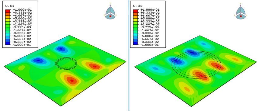
J. Compos. Sci. 2020, 4, x                                                                                   4 of 14

J. Compos. Sci. 2020, 4, 153                                                                                 4 of 13

as 2221. In the second scenario, the patches had scarf ratios of 40, 50, 120 and 240 and three steps in
their thickness. They are referred as 333 patches as each step of the patch is being bonded with three
plies of the
J. Compos. Sci. laminate.
                2020, 4, x Anisotropic behavior of the laminate was taken into consideration. For each ply,
                                                                                                     4 of 14
the lamina properties measured in house and are shown in Table 1.

          Figure 1. Illustration of rods that were placed onto the upper and bottom faces of the laminate.

     Table 2 shows the geometrical characteristics of the repaired laminate. It was assumed that the
lower layer of the plate had circular damage with a 10 mm diameter. Then, material was gradually
removed in layers from the laminate. Each layer that was removed had the same thickness as the
thickness of each ply of the base laminate. Afterwards, the circular repair patch was designed to
perfectly fit onto the plate in the region where the material was previously removed. The material
and the lay-up of the patch were the same with those of the base laminate in order to achieve the
maximum     strength
       Figure          and theofrestoration
               1. Illustration              of the
                                 rods that were     properties
                                                placed          of the and
                                                       onto the upper  undamaged    laminate
                                                                           bottom faces         (Figure 2).
                                                                                        of the laminate.
          Figure 1. Illustration of rods that were placed onto the upper and bottom faces of the laminate.
                                Table 2. Geometry of the laminate that was analysed.
                                Table 2. Geometry of the laminate that was analysed.
     Table 2 shows the geometrical characteristics of the repaired laminate. It was assumed that the
                                              Input Properties
lower layer of the plate had circular damage   Inputwith   a 10 mm diameter. Then, material was gradually
                                                       Properties
                                         Ply thickness = 0.186 mm
removed in layers from the laminate. Ply  Each    layer
                                              thickness= =that  was
                                                             0.186  mm removed had the same thickness as the
                                              Length       300  mm
thickness of each ply of the base laminate.             = 300 mmthe circular repair patch was designed to
                                                   Afterwards,
                                              Length
                                              Width
                                               Widththe
                                                        = 260mm
                                                       = 260
                                                               mm
perfectly fit onto the plate in the region where            material was previously removed. The material
                                             Flaw    size== 10
                                             Flaw size       10mm
                                                                mm
and the lay-up of the patch were the same         with those     of the base laminate in order to achieve the
                                  Scarf  ratio == 20,
                                   Scarfratio     20, 30,  40,50,
                                                      30, 40,  50,60,
                                                                    60,120,
                                                                          120,    240
                                                                                240
maximum strength and the restoration       of the[45,
                                                    properties    of the] undamaged laminate (Figure 2).
                                        Lay-up:
                                       Lay-up:     [45,−45,
                                                        −45,90,
                                                              90,0,0,9090
                                                                        /2 /2s]s

                               Table 2. Geometry of the laminate that was analysed.

                                               Input Properties
                                           Ply thickness = 0.186 mm
                                               Length = 300 mm
                                                Width = 260 mm
                                              Flaw size = 10 mm
                                    Scarf ratio = 20, 30, 40, 50, 60, 120, 240
                                         Lay-up: [45, −45, 90, 0, 90/2]s

                                     Figure 2. Schematic
                                     Figure2.  Schematic of
                                                         of patch
                                                            patch installation.
                                                                   installation.

     The repair patch was bonded onto the parent laminate. To simulate this bonding, cohesive interaction,
      Initially, five repaired plates with scarf ratios: 20, 30, 40, 50 and 60 and one damaged plate with
which is defined as a surface interaction property, was applied in each step between the repair patch
a 10 mm diameter through hole were analyzed in order to compare their response and evaluate the
and the base laminate, as previously studied and validated [22]. The cohesive properties have been
stiffness and strength restoration for each case.
calculated as a function of the mix-mode ratios, that are defined as the relative proportion of normal to
shear displacements at the cohesive zone, and the Mixed mode coefficient (Benzeggagh-Kenane criterion)
was set to the value of 2. Uncoupled traction-separation behaviour was taken into account, so that

                                     Figure 2. Schematic of patch installation.

     Initially, five repaired plates with scarf ratios: 20, 30, 40, 50 and 60 and one damaged plate with
a 10 mm diameter through hole were analyzed in order to compare their response and evaluate the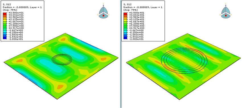
The repair patch was bonded onto the parent laminate. To simulate this bonding, cohesive
interaction, which is defined as a surface interaction property, was applied in each step between the
repair patch and the base laminate, as previously studied and validated [22]. The cohesive properties
have been calculated as a function of the mix-mode ratios, that are defined as the relative proportion
of normal to shear displacements at the cohesive zone, and the Mixed mode coefficient (Benzeggagh-
J. Compos. Sci. 2020, 4, 153
Kenane     criterion) was set to the value of 2. Uncoupled traction-separation behaviour was taken5 into      of 13

account, so that contact penalties enforce the cohesive constraint in normal and in tangential
direction.    Off-diagonal
contact penalties       enforceterms  in the elasticity
                                the cohesive   constraintmatrix wereand
                                                          in normal    set in
                                                                            totangential
                                                                               zero. Thedirection.
                                                                                           values of Off-diagonal
                                                                                                     the fracture
energies,
terms in the theelasticity
                  nominalmatrix
                             traction  stresses
                                    were  set to and
                                                 zero.the
                                                       Thepenalty stiffnesses
                                                           values of            thatenergies,
                                                                     the fracture    were utilized  are shown
                                                                                              the nominal        in
                                                                                                          traction
Table  3.
stresses and the penalty stiffnesses that were utilized are shown in Table 3.

                                             Table 3. Cohesive
                                             Table 3.          properties.
                                                      Cohesive properties.
                 GIC = 500                                                       nn = 2000 MPa/mm
                         GICJ/m                   τn =τ60  MPa              Knn K=
                                2
                              = 500 J/m2                n = 60 MPa                 2000 MPa/mm
                GIIC = 2.500 J/m2                 τt1 = 50 MPa                   Ktt = 1500 MPa/mm
                        GIIC = 2.500 J/m2              τt1 = 50 MPa         Ktt = 1500 MPa/mm
                GshC = 2.500
                        G     J/m
                              =
                                  2
                                2.500 J/m2        τt2 =τ50=MPa
                                                             50 MPa         Kss K  = 1500
                                                                                =ss1500   MPa/mm
                                                                                        MPa/mm
                          shC                          t2

      The interfacial failure is driven by the progressive degradation of the cohesive layer stiffness.
      The interfacial
The damage              failure
                modelling    wasisdefined
                                    drivenusingby the  progressive
                                                     a damage          degradation
                                                                 initiation  criterionofand
                                                                                          theacohesive     layer stiffness.
                                                                                                damage evolution       law.
The  damage     modelling    was  defined    using   a damage     initiation criterion   and  a damage
Initially the response was assumed to be linear until the maximum stress criterion was satisfied. Then,     evolution   law.
Initially
the  rate the  response
           of the         wasdegradation
                  stiffness    assumed to was  be linear  until the
                                                     described   frommaximum
                                                                        the power stress
                                                                                      lawcriterion
                                                                                           criterion was satisfied.
                                                                                                       that          Then,
                                                                                                             was defined
the rate  of the stiffness degradation      was  described   from   the power   law   criterion
using the fracture energy in mode I, II and III. The power law dictates failure in the normal or that was   defined  using
the fracture
tangential      energy
             mode    andinthat
                           mode    I, II is
                               failure   and   III. The by
                                            generated    power   law dictates
                                                            an equation          failureinto
                                                                           that takes     in the  normal
                                                                                              account   both orthe
                                                                                                                tangential
                                                                                                                   normal
mode    and  that failure  is generated     by  an  equation   that  takes into  account   both
and shear fracture energies. A schematic of the repair sizes is shown in Figure 3 where the size  the normal     and of
                                                                                                                     shear
                                                                                                                         the
fracture  energies.   A schematic    of
20, 40 and 60 patches are being compared.the  repair  sizes is shown    in Figure   3 where   the  size of  the 20, 40  and
60 patches are being compared.

           Figure 3. Sketch comparison of repaired plates with scarf ratios of (a) 20; (b) 40; and (c) 60.
           Figure 3. Sketch comparison of repaired plates with scarf ratios of (a) 20; (b) 40; and (c) 60.
3. Results
3. Results
      A graphical representation of the mechanical behavior of the repaired laminates as predicted by
the FEA   is given representation
      A graphical  in Figure 4, together
                                    of the with those ofbehavior
                                           mechanical    the undamaged        base laminate
                                                                   of the repaired           and
                                                                                     laminates asthe  damaged
                                                                                                  predicted by
laminate   with the 10 mm    through  hole. The  patches  with  scarf  ratio 50 and  60 had a similar
the FEA is given in Figure 4, together with those of the undamaged base laminate and the damaged      response,
as their curves practically coincide.
      The maximum compressive force that the undamaged plate can withstand, just prior to buckling,
is 80 kN, while for the damaged plate this force is less than 10 kN. Regarding the repaired plates,
the highest load before buckling corresponds to the repair cases with 50 and 60 scarf ratios and is about
40 kN. The plate with scarf ratio 20 had sufficiently lower buckling load at 17.5 kN. Finally, the repaired
laminate with 40 scarf ratio showed a lower buckling load of 12.5 kN. However, by examining the
patch with scarf ratio 40, it is remarkable that it was the less effective one, even compared to the patches
with 20 ratio. This can be justified since the buckling load is affected by the different buckling modes.
So, the response of the repaired laminate cannot be fully anticipated based on the scarf ratio since
different buckling modes could introduce earlier deformations. Nevertheless, it is evident that the
final failure load can be increased by increasing the scarf ratio up to a threshold value, which is 40 kN,
where no significant difference can be observed. So, applying a repair is vital as a repaired laminate
could have 5 times higher compressive strength compared to the strength of the damaged laminate.
However, the repair could only restore up to 50% of the buckling load of the undamaged plate.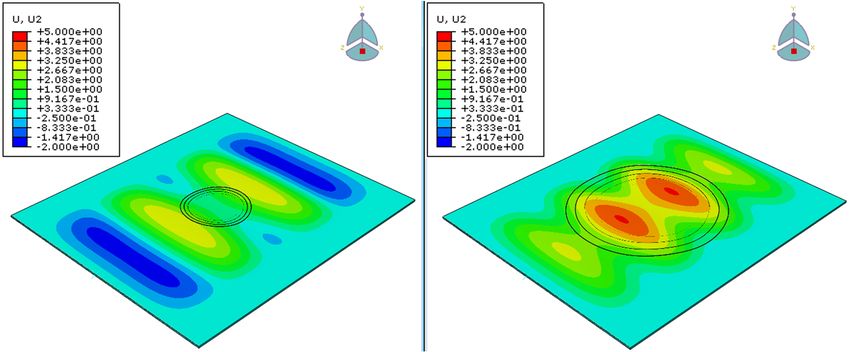
J. Compos. Sci. 2020, 4, x                                                                                   6 of 14

laminate with the 10 mm through hole. The patches with scarf ratio 50 and 60 had a similar response,
J. Compos. Sci. 2020, 4, 153                                                                   6 of 13
as their curves practically coincide.

      Figure4.4.Numerically
      Figure     Numericallypredicted force-displacement
                              predicted                  curvescurves
                                          force-displacement    of undamaged, damageddamaged
                                                                      of undamaged,   and repaired
                                                                                               andlaminates.
                                                                                                    repaired
      laminates.
       Table 4 summarizes the results presented above and correspond to the global buckling load of
the laminate.
        The maximum compressive force that the undamaged plate can withstand, just prior to
 buckling, is 80 kN, while for the damaged plate this force is less than 10 kN. Regarding the repaired
                              Table 4. Summarized results of global buckling loads.
 plates, the highest load before buckling corresponds to the repair cases with 50 and 60 scarf ratios
 and is about 40 kN. The plate Scarf withRatio
                                           scarf ratio 20 hadBuckling
                                                                  sufficiently
                                                                           Loadlower
                                                                                 (kN) buckling load at 17.5 kN.
 Finally, the repaired laminate with 20  40 scarf ratio showed a lower   17.5buckling   load of 12.5 kN. However,
 by examining the patch with scarf30      ratio 40, it is remarkable that 22 it was the less effective one, even
 compared to the patches with 20 ratio.  40 This can be justified since  12.5 the buckling load is affected by the
                                         50
 different buckling modes. So, the response       of the repaired laminate40 cannot be fully anticipated based
                                         60                               40
 on the scarf ratio since different buckling modes could introduce earlier deformations. Nevertheless,
                                     Damaged                              10
 it is evident that the final failure load can be increased by increasing
                                   Undamaged                              80      the scarf ratio up to a threshold
 value, which is 40 kN, where no significant difference can be observed. So, applying a repair is vital
 as a repaired laminate could have 5 times higher compressive strength compared to the strength of
       Comparative results for the undamaged and damaged plates as well as the repaired plates with
 the damaged laminate. However, the repair could only restore up to 50% of the buckling load of the
scarf ratio 20 and 60, that correspond to the smallest and largest patch, respectively, follow. The results
 undamaged plate.
represent the response of the plates the moment just before the failure occurred (failure using the
        Table 4 summarizes the results presented above and correspond to the global buckling load of
criterion Von Mises), which was detected from the force-displacement diagram and then selecting the
 the laminate.
closest frame to that moment from Abaqus’ field output.
       Figure 5 shows an illustrative      comparison
                              Table 4. Summarized         of of
                                                      results theglobal
                                                                   distributed
                                                                        bucklingVon
                                                                                  loads.Mises stresses just before
the failure for four plate cases; pristine, damaged, repaired with ratio 20 patch and repaired with
ratio 50 patch. It is observed that    Scarf
                                          theRatio
                                              biggest Buckling
                                                        patch canLoad      (kN) higher stresses before failure,
                                                                      withstand
                                            20                    17.5
whereas the smaller patch improved the performance of the damaged laminate, but to a smaller degree.
Compared to the damaged laminate, the       30biggest patch can22   increase the maximum stress capacity of the
structure even six times. Regarding the40                         12.5 achieve approximately two times higher
                                             smaller patch, it could
stress capacity. Nevertheless, none of the  50 patches managed40to recover the stress capacity of the pristine
laminate before failure.                    60                     40
                                        Damaged                    10
       The worst and the best performed repair scenarios were picked, the 20 and the 50 scarf ratios,
respectively, for a direct comparison Undamaged
                                          between the weakest 80   and the strongest patch. It has to be noticed
that the patch with scarf ratio 60 was as strong as the 50 based on the comparison above, but more
       Comparative
material              results for
           has to be removed    sothe undamaged
                                   it was excluded.and damaged
                                                    Figure       plates
                                                           6 presents   asdisplacement
                                                                      the  well as the repaired plates
                                                                                         magnitude  onwith
                                                                                                       the
 scarf  ratio 20 and   60, that correspond   to the smallest and  largest patch, respectively, follow. The
two plates. This value represents an equivalent of the X, Y, Z displacements for each point, in this case
for each element, of the laminate. It is notable that the maximum magnitude on the left laminate is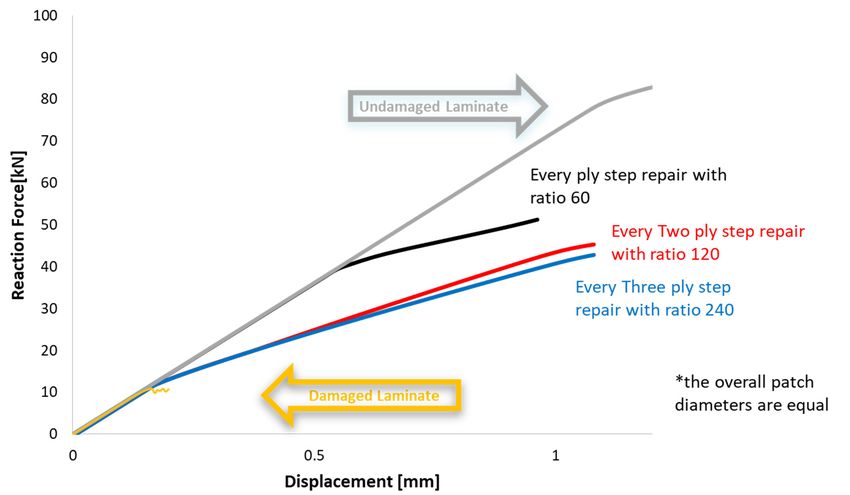
the closest frame to that moment from Abaqus’ field output.
       Figure 5 shows an illustrative comparison of the distributed Von Mises stresses just before the
failure for four plate cases; pristine, damaged, repaired with ratio 20 patch and repaired with ratio 50
patch. It is observed that the biggest patch can withstand higher stresses before failure, whereas the
smaller     patch improved the performance of the damaged laminate, but to a smaller degree.
 J. Compos. Sci. 2020, 4, 153                                                                                  7 of 13
Compared to the damaged laminate, the biggest patch can increase the maximum stress capacity of
the structure even six times. Regarding the smaller patch, it could achieve approximately two times
 approximately
higher               3.37 mmNevertheless,
         stress capacity.       while on the right
                                              noneisof4.5 mm.
                                                        the    This can
                                                            patches     be justified
                                                                     managed         due tothe
                                                                               to recover   the stress
                                                                                                 fact that the latter
                                                                                                        capacity   of
 can  withstand     bigger    displacements
the pristine laminate before failure.        before failure  occurs.

      Figure 5. Breakdown using the criterion Von Mises (a): pristine plate, (b): damaged plate with a 5 mm
      Figure
      radius 5.   Breakdown
               hole,           using
                     (c): repaired   the with
                                   plate criterion
                                               ratioVon  Mises
                                                     scarf      (i): repaired
                                                           20, (d):  pristine plate, (ii): damaged
                                                                              plate with             plate
                                                                                            ratio scarf 60. with a 5 mm
J. Compos. Sci.hole,
      radius    2020,(iii):
                      4, x repaired plate with ratio scarf 20, (iv): repaired plate with ratio scarf 60.                8 of 14

     The worst and the best performed repair scenarios were picked, the 20 and the 50 scarf ratios,
respectively, for a direct comparison between the weakest and the strongest patch. It has to be noticed
that the patch with scarf ratio 60 was as strong as the 50 based on the comparison above, but more
material has to be removed so it was excluded. Figure 6 presents the displacement magnitude on the
two plates. This value represents an equivalent of the X, Y, Z displacements for each point, in this
case for each element, of the laminate. It is notable that the maximum magnitude on the left laminate
is approximately 3.37 mm while on the right is 4.5 mm. This can be justified due to the fact that the
latter can withstand bigger displacements before failure occurs.

      Figure
      Figure 6.6. Deformed
                  Deformedbody
                           body(U, Magnitude)
                                 (U,          forfor
                                     Magnitude)   repair withwith
                                                     repair   20 repair ratio (left)
                                                                   20 repair  ratio and
                                                                                     (left)50and
                                                                                              repair
                                                                                                  50 ratio (right).
                                                                                                      repair  ratio
      (right).
      Going individually to each axis, Figure 7 illustrates the displacements in the X, Y and Z- axis
and represents    the case when
      Going individually     to eachthe  applied
                                      axis, Figuredisplacement     was
                                                   7 illustrates the    approximately
                                                                      displacements      1.2 X,
                                                                                     in the  mm    i.e., Z-
                                                                                                Y and    just before
                                                                                                            axis and
the failure for both  plates.   For  the patch  with  ratio  20 the maximum    displacement
represents the case when the applied displacement was approximately 1.2 mm i.e., just before thein the   X-axis  was
0.1 mm,for
failure  while
            boththe  maximum
                   plates. For thedisplacement
                                     patch with in  the20
                                                 ratio   Y-axis  was 3.25 mm.
                                                            the maximum        In regard tointhe
                                                                            displacement       thedisplacement
                                                                                                    X-axis was 0.1 in
the Z-axis, corresponds     to the  loading-axis  displacements.     For the patch  with  ratio
mm, while the maximum displacement in the Y-axis was 3.25 mm. In regard to the displacement in  50  the   maximum
displacement    in the X-axis
the Z-axis, corresponds         wasloading-axis
                            to the    0.1 mm, while    in the Y-axisFor
                                                  displacements.      wasthe
                                                                           5 mm.
                                                                             patchFrom
                                                                                    withthe   above,
                                                                                          ratio 50 theit maximum
                                                                                                          is evident
that the two  laminates   were   similarly  deformed   in the  X-axis. However,  in the Y-axis  the
displacement in the X-axis was 0.1 mm, while in the Y-axis was 5 mm. From the above, it is evident   laminate   with
that the two laminates were similarly deformed in the X-axis. However, in the Y-axis the laminate
with the ratio 50 had 35% higher displacements, as it withstands a bigger load and had a different
buckling mode before failure.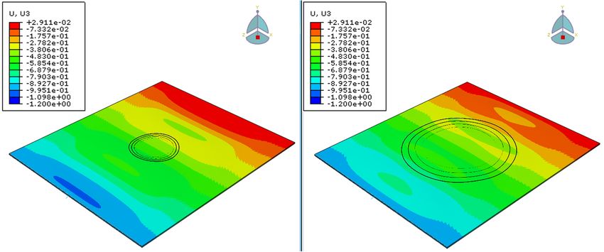
represents the case when the applied displacement was approximately 1.2 mm i.e., just before the
failure for both plates. For the patch with ratio 20 the maximum displacement in the X-axis was 0.1
mm, while the maximum displacement in the Y-axis was 3.25 mm. In regard to the displacement in
the Z-axis, corresponds to the loading-axis displacements. For the patch with ratio 50 the maximum
J. Compos. Sci. 2020,
displacement in 4,the
153X-axis was 0.1 mm, while in the Y-axis was 5 mm. From the above, it is evident
8 of 13
that the two laminates were similarly deformed in the X-axis. However, in the Y-axis the laminate
with the ratio 50 had 35% higher displacements, as it withstands a bigger load and had a different
the ratio 50 had 35% higher displacements, as it withstands a bigger load and had a different buckling
buckling mode before failure.
mode before failure.
J. Compos. Sci. 2020, 4, x 9 of 14
Figure 7.
Figure 7. Displacements
Displacementsinin
X, X, Y and
Y and Z-axis
Z-axis for repair
for repair with
with 20 20column)
(left (left column) and 50
and 50 scarf scarf
ratio ratio
(right (right
column).
column).
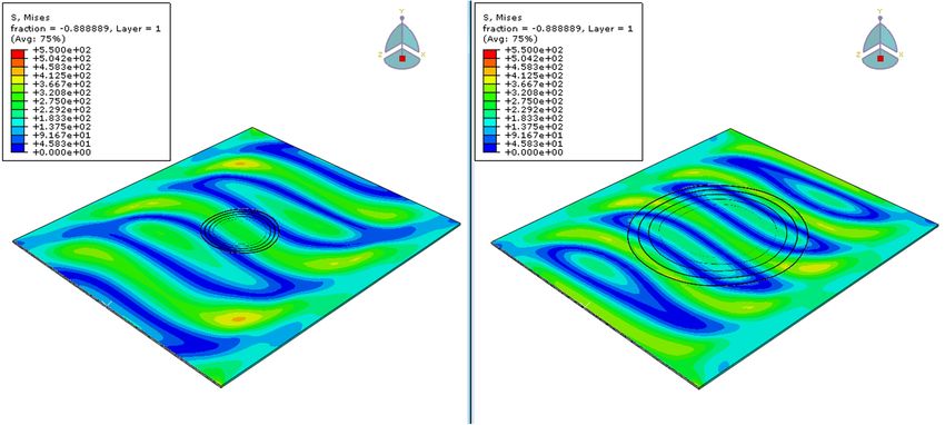
Moving to stresses, the stress distribution of the two laminates is shown below in Figure 8.
The figures
Movingwere captured
to stresses, theat the same
stress time frame
distribution of theas before,
two just before
laminates failure,
is shown belowtoinallow a 8.
Figure direct
The
comparison
figures wereand better understanding
captured of theframe
at the same time response
as of the repaired
before, laminates.
just before failure, to allow a direct
comparison and better understanding of the response of the repaired laminates.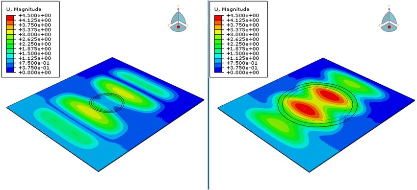
Figure 7. Displacements in X, Y and Z-axis for repair with 20 (left column) and 50 scarf ratio (right
     column).

      Moving to stresses, the stress distribution of the two laminates is shown below in Figure 8. The
 figures   were
J. Compos. Sci.    captured
                2020, 4, 153 at the same time frame as before, just before failure, to allow a direct
                                                                                                9 of 13
 comparison and better understanding of the response of the repaired laminates.

      Figure
      Figure 8. Distribution trends-based
             8. Distribution trends-based criterion
                                          criterion Von
                                                    Von Mises
                                                        Mises for
                                                               for repair
                                                                   repair with
                                                                          with20
                                                                               20(left)
                                                                                  (left)and
                                                                                        and50
                                                                                            50(right)
                                                                                               (right)ratio.
                                                                                                       ratio.

      Based
      Based on
             on the
                  the Von
                       Von Mises
                           Mises criterion,
                                  criterion, the
                                              the maximum
                                                  maximum stress
                                                             stress that
                                                                     that occurred
                                                                          occurred on
                                                                                   on the
                                                                                       the laminate
                                                                                            laminate with
                                                                                                      with the
                                                                                                            the
smaller  patch  is 450 MPa, while on  the laminate  with 50 scarf ratio the maximum   stress
 smaller patch is 450 MPa, while on the laminate with 50 scarf ratio the maximum stress is    is approximately
400 MPa. The smaller patch had higher stresses than the laminate with the bigger patch, at the same
time frame. That means that it will more quickly reach its ultimate strength/fracture point.
      From the stress distributions in Figure 9, it can be easily observed that the maximum compressive
stress in the X-axis for both laminates is about 550 MPa. On the other hand, the maximum tensile
stress on the laminate with 20 ratio is 320 MPa, while on the laminate with 50 ratio is about 240 MPa.
This difference would result in an earlier matrix failure of the plate with the smaller patch, that would
potentially lead to delaminations and final failure. In the Y-axis, the maximum compressive stress
for both the laminates is about 40 MPa, while the maximum tensile stress for the smaller and the
larger patch is 28 MPa and 21 MPa, respectively. The shear stresses in the XY plane are similarly
distributed on both laminas. However, the maximum stresses occurred on the 4 edges of the lamina
for the laminate with 20 ratio and at the center of the plate for the laminate with 50 scarf ratio. It can be
said that as the higher stresses were reached earlier by the plate with the 20 scarf ratio, it would have
the worst performance, verifying the comparison of Figure 4.
      Results showed that it is very important to repair a composite structure that has been damaged,
as the repair would not only prevent damage propagation but will also restore the laminate’s stiffness
up to 4 times and its maximum stress capacity up to 6 times compared to the damaged.
      Moving to the effect of the patch steps compared to the number of the plies that constitute that
base laminate, Figures 10 and 11 present the response of the repair patch with 4 and 3 steps through
its thickness, respectively. This means that instead of having a ply by ply step repair, the patch steps
will go every two and three plies, respectively. The two-ply step repair will result in a four-step patch
(2221), while having a three step repair will result in a three-step patch (333).
      Based on Figure 10, it is evident that the scarf ratio does not significantly affect the response of
the repair patch. Moreover, the buckling load is lower compared to the damage scenario and is equal
to 14 kN, which is more than 4 times lower than the corresponding load of the 9-step patch with
50 scarf ratio.
      The same behavior was observed for the scenario with 3 steps in its thickness (Figure 11) where
the buckling load was equal to 12.5 kN for all scarf ratios and was slightly lower than the patch that
consisted of 4 steps. A minor increase of this load can be observed in the patch with ratio 120, where it
is equal to 17 kN, but is again lower than the plate with 9 steps and 50 scarf ratio.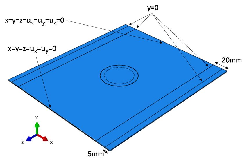
compressive stress for both the laminates is about 40 MPa, while the maximum tensile stress for the
smaller and the larger patch is 28 MPa and 21 MPa, respectively. The shear stresses in the XY plane
are similarly distributed on both laminas. However, the maximum stresses occurred on the 4 edges
of the lamina for the laminate with 20 ratio and at the center of the plate for the laminate with 50 scarf
ratio.
J.     It can
   Compos.      be said
           Sci. 2020,      that as the higher stresses were reached earlier by the plate with the 20 scarf10ratio,
                      4, 153                                                                                 of 13
it would have the worst performance, verifying the comparison of Figure 4.

J. Compos. Sci. 2020, 4, x                                                                                    11 of 14

      Figure 9. Breakdown strains S11, S22 and S12 for repair with 20 (left column) and 50 (right column) ratio.
      Figure 9. Breakdown strains S11, S22 and S12 for repair with 20 (left column) and 50 (right column)
      ratio.

      Results showed that it is very important to repair a composite structure that has been damaged,
as the repair would not only prevent damage propagation but will also restore the laminate’s stiffness
up to 4 times and its maximum stress capacity up to 6 times compared to the damaged.
      Moving to the effect of the patch steps compared to the number of the plies that constitute that
base laminate, Figures 10 and 11 present the response of the repair patch with 4 and 3 steps through
its thickness, respectively. This means that instead of having a ply by ply step repair, the patch steps
will go every two and three plies, respectively. The two-ply step repair will result in a four-step patch
(2221), while having a three step repair will result in a three-step patch (333).
Moving to the effect of the patch steps compared to the number of the plies that constitute that
base laminate, Figures 10 and 11 present the response of the repair patch with 4 and 3 steps through
its thickness, respectively. This means that instead of having a ply by ply step repair, the patch steps
will go every two and three plies, respectively. The two-ply step repair will result in a four-step patch
J.(2221),
Compos. while having
Sci. 2020, 4, 153 a three step repair will result in a three-step patch (333). 11 of 13
Patch with 4 steps in its thickness
50
45
Reaction Force [kN] 40
35
30
25 2221-SR 30
20
15 2221-SR 60
10 2221-SR 120
5
0
0 0.2 0.4 0.6 0.8 1 1.2
J. Compos. Sci. 2020, 4, x 12 of 14
Displacement [mm]
consisted of 4 steps. A minor increase of this load can be observed in the patch with ratio 120, where
Figure 10. Displacement-Reaction Force curve for repaired laminated with patch with 4 steps through
it isits
equal
Figure to
10.17
thickness kN,30,but
60 is again
Displacement-Reaction
and and lower
Force
120 scarf than the
curve
ratio.
forplate withlaminated
repaired 9 steps and
with50 scarf
patch ratio.
with 4 steps through
its thickness and 30, 60 and 120 scarf ratio.
Patch with 3 steps in its thickness
Based on Figure 50 10, it is evident that the scarf ratio does not significantly affect the response of
45
the repair patch. Moreover, the buckling load is lower compared to the damage scenario and is equal
Reaction Force[kN]
40
to 14 kN, which is more 35 than 4 times lower than the corresponding load of the 9-step patch with 50
scarf ratio. 30
The same behavior 25 was observed for the scenario with 3 steps in333- SR 40
its thickness (Figure 11) where
the buckling load was20equal to 12.5 kN for all scarf ratios and was slightly 333- SR 50
lower than the patch that
15 333- SR 120
10
333- SR 240
5
0
0 0.2 0.4 0.6 0.8 1 1.2
Displacement [mm]
Figure 11. Displacement-Reaction Force curve for of repaired laminated with patch with 3 steps in
Figure 11. Displacement-Reaction Force curve for of repaired laminated with patch with 3 steps in its
its thickness.
thickness.
Figure 12 summarizes the maximum buckling and failure loads prior to failure for a damaged,
Figure 12 summarizes the maximum buckling and failure loads prior to failure for a damaged,
an undamaged and three repaired plates. The overall patch diameter for the three repaired plates is
an undamaged and three repaired plates. The overall patch diameter for the three repaired plates is
equal. However, they have different number of plies in each step, varying from 1 to 3. The repair patches
equal. However, they have different number of plies in each step, varying from 1 to 3. The repair
that have 2 and 3 plies in each step increase the maximum force that the structure can withstand but
patches that have 2 and 3 plies in each step increase the maximum force that the structure can
slightly increase the buckling load compared with the damaged plate. On the other hand, compared to
withstand but slightly increase the buckling load compared with the damaged plate. On the other
the damaged plate, the patch that has one ply in each step increases buckling load 4 times and the
hand, compared to the damaged plate, the patch that has one ply in each step increases buckling load
failure load from 10 kN to 50 kN, and only 40% less compared to the undamaged plate. These means
4 times and the failure load from 10 kN to 50 kN, and only 40% less compared to the undamaged
that the total strength of the repaired laminate is not only affected by the scarf ratio and the overall
plate. These means that the total strength of the repaired laminate is not only affected by the scarf
diameter of the patch, but also by the thickness of the step of the repair patch.
ratio and the overall diameter of the patch, but also by the thickness of the step of the repair patch.
To summarise, if damage occurs, it is only practical to induce a repair patch that has one ply in
each step. However, more experiments need to be conducted in order to verify which is the optimal
scarf ratio. The outcome of the current study is that the higher the scarf ratio, the stronger the repaired
structure. However, this is valid only up to a certain value of the scarf ratio. Above that value,
no significant increase of the total strength can be observed. For the scenario that the repair patch has
equal number of steps as the base laminate, there was a remarkable surge of the failure load while the
scarf ratio was increasing from 20 to 50. The scarf ratio 50 was a threshold, above which no significant
change in the strength that could be attained with the use of the repair patch could be seen.patches that have 2 and 3 plies in each step increase the maximum force that the structure can
withstand but slightly increase the buckling load compared with the damaged plate. On the other
hand, compared to the damaged plate, the patch that has one ply in each step increases buckling load
4 times and the failure load from 10 kN to 50 kN, and only 40% less compared to the undamaged
plate. These means that the total strength of the repaired laminate is not only affected by the scarf
J. Compos. Sci. 2020, 4, 153 12 of 13
ratio and the overall diameter of the patch, but also by the thickness of the step of the repair patch.
Figure12.12.Displacement-Reaction
Figure force
Displacement-Reaction graph
force for damaged,
graph undamaged
for damaged, and various
undamaged andrepaired
variouslaminates
repaired
with equal overall patch diameter.
laminates with equal overall patch diameter.
4. Discussion
To summarise, if damage occurs, it is only practical to induce a repair patch that has one ply in
each step.though
Even many
However, studies
more examined
experiments thetorepair
need methods in
be conducted in order
composite materials,
to verify which the literature
is the optimal
isscarf
limited regarding models studying the influence of steps in stepped scarfs. The purpose of this
ratio. The outcome of the current study is that the higher the scarf ratio, the stronger the repaired
investigation was to examine how the geometry of a stepped repair patch influences the behaviour of a
repaired plate under compressive loading.
It was evident that the stepped scarf repair patch significantly increased the strength of the
damaged plate and recovered its strength up to 4 times. However, none of the examined patches was
able to fully recover the strength of the undamaged laminate. To optimize the recovery of the damaged
laminate, it is recommended to use patches with number of steps equal to the number of the repaired
plies. It seems as though decreasing this number will significantly plummet the estimated failure load
of the repaired structure.
Also, it is suggested that a parametric analysis prior to repairs be conducted, as a bigger patch
does not necessarily mean greater strength and vice versa. Wisely choosing the geometry of the repair
patch that will be used is vital, since a wrong decision could deteriorate the mechanical performance of
the structure and also could lead to increased material removal that affects the overall repair procedure
time and cost.
However, further study is suggested to be carried out that would allow more scarf ratios to be
examined for more accurate and general outcomes.
Author Contributions: Conceptualization, V.K., S.P. and T.L.; methodology, M.P., O.K.T. and S.P.; software,
M.P., O.K.T. and S.P.; validation, M.P., O.K.T. and S.P.; formal analysis, M.P., O.K.T. and S.P.; investigation, M.P.,
O.K.T. and S.P.; resources, V.K. and T.L.; data curation, M.P., O.K.T. and S.P.; writing—original draft preparation,
M.P., O.K.T. and S.P.; writing—review and editing, V.K., S.P. and T.L.; visualization, V.K., S.P. and T.L.; supervision,
S.P. and V.K.; project administration, V.K. and T.L. All authors have read and agreed to the published version of
the manuscript.
Funding: This research was funded by European Union’s H2020 Programme grant number [665238].
Acknowledgments: The research leading to the results has received funding from the FET-OPEN Programme of
the European Union’s H2020 Programme under REA grant agreement N◦ [665238] CompInnova.
Conflicts of Interest: Authors declare no conflict of interest.J. Compos. Sci. 2020, 4, 153 13 of 13
References
1. Chan, W.S.; Vedhagiri, S. Analysis of Composite Bonded/Bolted Joints Used in Repairing. J. Compos. Mater.
2001, 35, 1045–1061. [CrossRef]
2. Broughton, W.R.; Crocker, L.E.; Gower, M.R.L. Design Requirements for Bonded and Bolted Composite Structures.
2002. Available online: http://eprintspublications.npl.co.uk/2130/1/MATC65.pdf (accessed on 15 April 2020).
3. Harman, A.; Wang, C.H. Improved design methods for scarf repairs to highly strained composite aircraft
structure. Compos. Struct. 2006, 75, 132–144. [CrossRef]
4. Soutis, C.; Duan, D.M.; Goutas, P. Compressive behaviour of CFRP laminates repaired with adhesively
bonded external patches. Compos. Struct. 1999, 45, 289–301. [CrossRef]
5. Charalambides, M.N.; Hardouin, R.; Kinloch, A.J.; Matthews, F.L. Adhesively-bonded repairs to fibre
composite materials I: Experimental. Compos. Part A Appl. Sci. Manuf. 1998, 29A, 1371–1381. [CrossRef]
6. Zhang, H.; Motipalli, J.; Lam, Y.C.; Baker, A. Experimental and finite element analyses of the post-buckling
behaviour of repaired composite panels. Compos. Part A Appl. Sci. Manuf. 1998, 29A, 1464–1471. [CrossRef]
7. Wang, C.H.; Venugopal, V.; Peng, L. Stepped Flush Repairs for Primary Composite Structures. J. Adhes. 2015,
91, 95–112. [CrossRef]
8. Lubkin, J.L. A Theory of Elastic Scarf Joints. J. Appl. Mech. 1957, 24, 255–260.
9. Sumida, P.T.; Hart-Smith, L.J.; Pride, R.A.; Lil, W. Filamentary Composite Reinforcement of Metal Structures.
In Proceedings of the SPI 28th Annual Western Conference, Coronado, CA, USA, 5–7 May 1971; pp. 74–90.
10. Erdogan, F.; Ratwani, M. Stress Distribution in Bonded Joints. J. Compos. Mater. 1971, 5, 378–393. [CrossRef]
11. Hart-Smith, L. Adhesive-Bonded Scarf and Stepped-Lap Joints; Tech. Rep. NASA CR 112237; Langley Research
Center: Hampton, VA, USA, 1973.
12. Ahn, S.H.; Springer, G.S. Repair of Composite Laminates, Federal Aviation Administration William J.
Hughes Technical Center’s 2000, DOT/FAA/AR-00/46. Available online: https://www.coursehero.com/file/
58049601/Repair-of-Composite-Laminatespdf/ (accessed on 6 February 2020).
13. Kumar, S.B.; Sridhar, I.; Sivashanker, S.; Osiyemi, S.O.; Bag, A. Tensile failure of adhesively bonded CFRP
composite scarf joints. Mater. Sci. Eng. B 2006, 132, 113–120. [CrossRef]
14. Gunnion, A.J.; Herszberg, I. Parametric study of scarf joints in composite structures. Compos. Struct. 2006,
75, 364–376. [CrossRef]
15. Baker, A.A.; Chester, R.J.; Hugo, G.R.; Radtke, T.C. Scarf repairs to highly strained graphite/epoxy structure.
Int. J. Adhes. Adhes. 1999, 19, 161–171. [CrossRef]
16. Wang, C.H.; Gunnion, A.J. On the design methodology of scarf repairs to composite laminates.
Compos. Sci. Technol. 2008, 68, 35–46. [CrossRef]
17. Bendemra, H.; Compston, P.; Crothers, P.J. Optimisation study of tapered scarf and stepped-lap joints in
composite repair patches. Compos. Struct. 2015, 130, 1–8. [CrossRef]
18. Odi, R.A.; Friend, C.M. An improved 2D model for bonded composite joints. Int. J. Adhes. Adhes. 2004, 24,
389–405. [CrossRef]
19. Tzetzis, D.; Hogg, P.J. Experimental and finite element analysis on the performance of vacuum-assisted resin
infused single scarf repairs. Mater Des. 2008, 29, 436–449. [CrossRef]
20. Campilho, R.D.S.G.; de Moura, M.F.S.F.; Domingues, J.J.M.S. Stress and failure analyses of scarf repaired
CFRP laminates using a cohesive damage model. J. Adhes. Sci. Technol. 2007, 21, 855–870. [CrossRef]
21. Campilho, R.D.S.G.; de Moura, M.F.S.F.; Pinto, A.M.G.; Morais, J.J.L.; Domingues, J.J.M.S. Modelling the
tensile fracture behaviour of CFRP scarf repairs. Compos. Part B Eng. 2009, 40, 149–157. [CrossRef]
22. Psarras, S.; Loutas, T.; Galanopoulos, G.; Karamadoukis, G.; Sotiriadis, G.; Kostopoulos, V. Evaluating
experimentally and numerically different scarf-repair methodologies of composite structures. Int. J. Adhes. Adhes.
2019, 97, 102495. [CrossRef]
23. Hashin, Z. Failure Criteria for Unidirectional Fiber Composites. J. Appl. Mech. 1980, 47, 329–334. [CrossRef]
Publisher’s Note: MDPI stays neutral with regard to jurisdictional claims in published maps and institutional
affiliations.
© 2020 by the authors. Licensee MDPI, Basel, Switzerland. This article is an open access
article distributed under the terms and conditions of the Creative Commons Attribution
(CC BY) license (http://creativecommons.org/licenses/by/4.0/).You can also read