The Best Solution For Process Piping Installations - Steel & O'Brien
←
→
Page content transcription
If your browser does not render page correctly, please read the page content below
®

    The Best
 Solution For
     Process
       Piping
Installations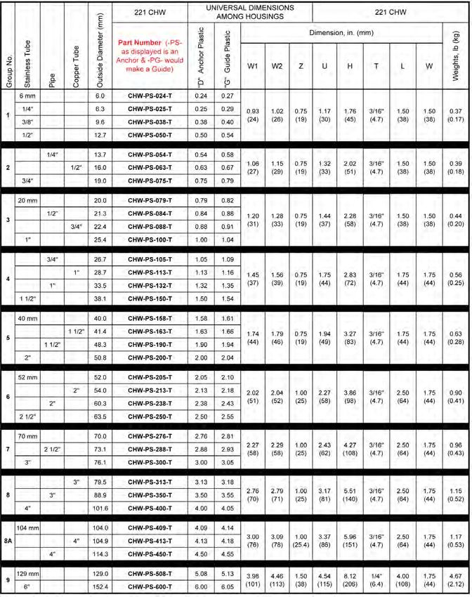
Forward

Introduction                                                                Applications
Thank you for choosing Behringer, the world’s leading manufacturer of       Behringer clamps are used in may different types of applications rang-
Pipe and Tube supports. Behringer has been manufacturing pipe               ing from low pressure lubrication and water systems to high pressure
clamps and support systems for over 30 years, and has developed a rep-      hydraulic and process systems. Anywhere that there are pipes, tubes,
utation in the industrial and sanitary markets that is second to none. We   or hoses is a viable application for Behringer clamps. Behringer
have made developments and product improvements over the years              clamps are used in the following markets and applications most fre-
both strengthening and broadening our product offering. This is evident     quently:
in the breadth of our line and ability to accommodate new applications
and designs. You can count on Behringer for all your clamping and sup-      Mobile Equipment                              Power Generation
port requirements.                                                          Mining Equipment                              Pulp and Paper
                                                                            Offshore and Marine Applications              Industrial Hydraulics
Product                                                                     Shipbuilding                                  Power Units
Behringer Hygienic Tube Supports are designed to meet the high              Instrumentation                               Agricultural Equipment
demands of process piping in hygienic service applications. The auto-       Nuclear                                       OEM Machinery
matic slope adjustment feature of the CH Series Dynamic hanger will         General Construction
promote drainability of the piping without imparting unnecessary stress     Electrical / Mechanical Contracting
into the piping. Drainability is a critical design feature in hygienic      Process Piping
process piping. Behringer Sanitary Pipe and Tube Supports are avail-        Pharmaceutical / Biotechnology
able in a wide range of sizes and configurations and are offered with       Food and Dairy
both an anchor or guide insert to meet the needs of any application.        Beverage

Behringer offers many different series and within each series there are     Assistance
many different configurations available. We offer options for mounting      Behringer Corporation has a competent and highly skilled staff of
such as welding, bolting, rail and strut mounting, double, and group        inside sales and customer service personnel available to assist you
mounting, etc. Behringer always welcomes a challenge, and would be          with any of your needs. Behringer can be reached in the following
happy to work with you to design a product that is custom-tailored to       ways:
your application. This is where many of our developments are first gen-
erated, and helps to further progress the complexity of our product.
Challenge us with your requirements.                                        Post Mail:        Behringer Corporation
                                                                                              17 Ridge Road
Guarantee                                                                                     Branchville, NJ 07826
Behringer Corporation, hereinafter called the “MANUFACTURER”,               Telephone:        +1 (973) 948-0226
guarantees that this product shall be free from defects in workmanship      Fax:              +1 (973) 948-2562
and materials. THIS GUARANTEE IS IN LIEU OF ALL OTHER                       Email:            cserv@behringersystems.com
GUARANTEES EITHER EXPRESSED OR IMPLIED, INCLUDING
GUARANTEES FOR FITNESSFOR PURPOSE INTENDED. The                             Our regular business hours are Monday through Friday, 8AM - 5 PM
MANUFACTURER'S liability is limited to the replacement of any               Eastern Time. For after-hours service, please contact your regional
materials which, after inspection by the MANUFACTURER at it's sole          sales manager.
option, are found to be defective. The MANUFACTURER will honor
only those claims that are presented to it within one hundred eighty        Please Read
(180) days of the delivery of the materials to the purchaser. The MAN-      The information contained in this document is provided as an aid in
UFACTURER SPECIFICALLY DISCLAIMS ANY AND ALL LIA-                           properly selecting products and/or options. It is intended to be used by
BILITY FOR CONSEQUENTIAL DAMAGES. The MANUFAC-                              technically experienced users for general reference only. The supplier
TURER shall not be liable for any damages which arise out of the mis-       assumes no responsibility or liability for the accuracy or completeness
use or abuse of the products.                                               of this document, as well as results obtained by the use of this infor-
                                                                            mation. Due to the variety of possible operating conditions, it is high-
                                                                            ly recommended that the user make their own tests to determine the
                                                                            safety and suitability of all products and combinations thereof. The
                                                                            user is solely responsible for final determination of such conditions.

 ii          Catalog CHSAN1114
CH SERIES HAS
                         ALL YOUR ANGLES COVERED...
          Compact
          Hygienic
                  CH
            Series
           Hangers

                             The innovative CH Series hangers design was developed with the
                             input of engineers, contractors, end users and Behringer's
                             strong understanding of hygienic tube and pipe applications.
                             These compact High Purity hangers answer industry concerns,
                             while incorporating several contractor time-saving benefits. The
                             tension ring connection on the Dynamic Hanger allows the clamp
                             bodies to self adjust, independent of the hanging rod, to the
                             tube's slope. This attribute reduces internal stress on the tube,
                             as well as, eliminating an entire step during slope adjustment. The
                             ability to make these adjustments, while the hanger is secured to
                             the tubing, eliminates the step of retesting the slope after the
                             hangers have been mounted. The combined use of the CH, CHT,
                             CHR & CHW supports along with the telescoping stanchions
                             permits line adjustment in the x, y and z axis's. What could prove
                             to be biggest saver is these are packaged and installed as a one
                             piece unit. No loose parts and wasted time gathering pieces and
                             assembling components on ladders and space restricted areas.
                             These benefits ultimately create a quality job.

                                                                       fi

PHONE :   973›948›0226           WWW   .BEHRINGERSYSTEMS.COM         Catalog CHSAN1114        iii
                                         PATENT PENDING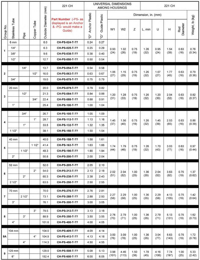
New Items & Accessories
          Height Adjustment Coupling                    Convenient T-Handle Nut Driver - (CHTOOL)

            Ball Swivel Joint - (SWVJ)                    Fig. 207 Thermal Expansion Guide (TEG)
                                                                    for Plastic Inserts

               Wing Bolt - (CWBT)                            Fig. 65 Swivel Plate - (SB-SWV)

                                     CH Height Adjuster - (CHADJ)
                                         • Easy field adjustment of the support height position to
                                           optimize drainability

                                         • Adjustment range is +/- 1.000 in. from the midpoint
                                           setting (2” total range)

                                         • All components are captive for safety

                                         • Compliant with ASME BPE requirements

                                                                      fi

iv   Catalog CHSAN1114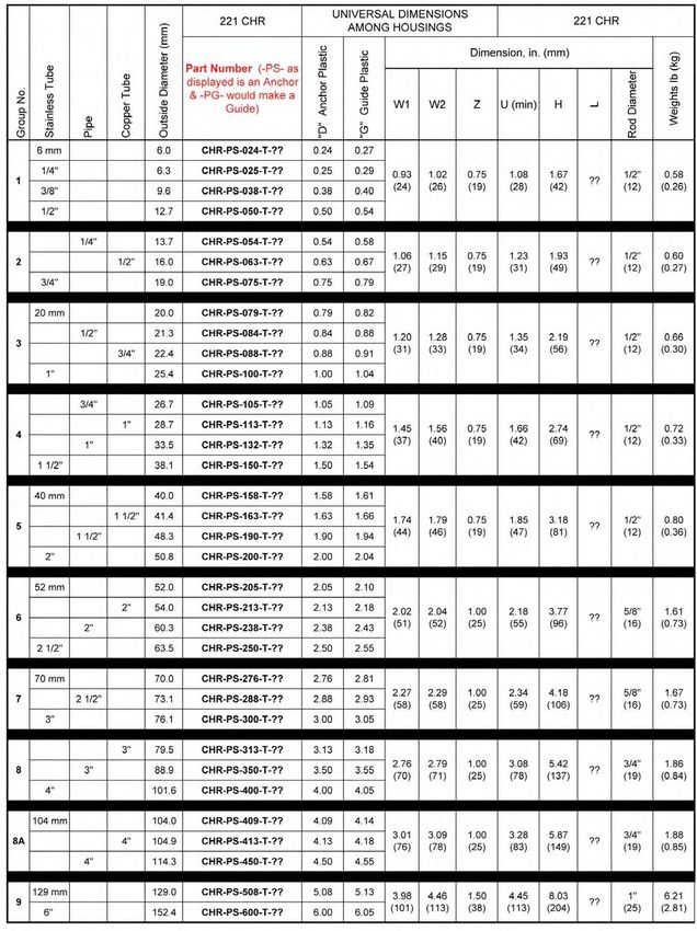
Table of Contents

CH Series
Fig. 221
     CH - Dynamic Mount Hanger                                             Pages 4 - 5
     CHR - Rigid Mount Hanger                                               Pages 6 - 7
     CHW - Weld Plate Mount Support                                        Pages 8 - 9
     CHT - Threaded Mount Hanger                                         Pages 10 - 11
Fig. 245 - Threaded Support Rod                                                Page 12

Stanchions
Fig.   223   -   Telescopic Adjusting Round Floor Mount Stand                   Page   13
Fig.   224   -   CH Series Rod Stand Plate                                      Page   14
Fig.   225   -   Telescopic Adjusting Stanchion - Hang Mount                    Page   15
Fig.   226   -   Telescopic Adjusting Stanchion - Floor Mount                   Page   16

Smooth Bore Series
Fig.   200   -   Smooth   Bore   Weld Plate Mount                               Page   19
Fig.   201   -   Smooth   Bore   Hang Plate Mount                               Page   20
Fig.   202   -   Smooth   Bore   Base Plate Mount                               Page   21
Fig.   203   -   Smooth   Bore   RAL-1 Rail Mounting                            Page   22
Fig.   204   -   Smooth   Bore   Stacking Kit                                   Page   23
Fig.   211   -   Smooth   Bore   Unistrut Mount                                 Page   24
Fig.   221   -   Smooth   Bore   Rod Mount                                      Page   25

Miscellaneous
Technical Data Material Properties,                                        Page 26-30
Slope Conversion Chart, Shear Force Diagram                                                 fi

                                                                Catalog CHSAN1114            1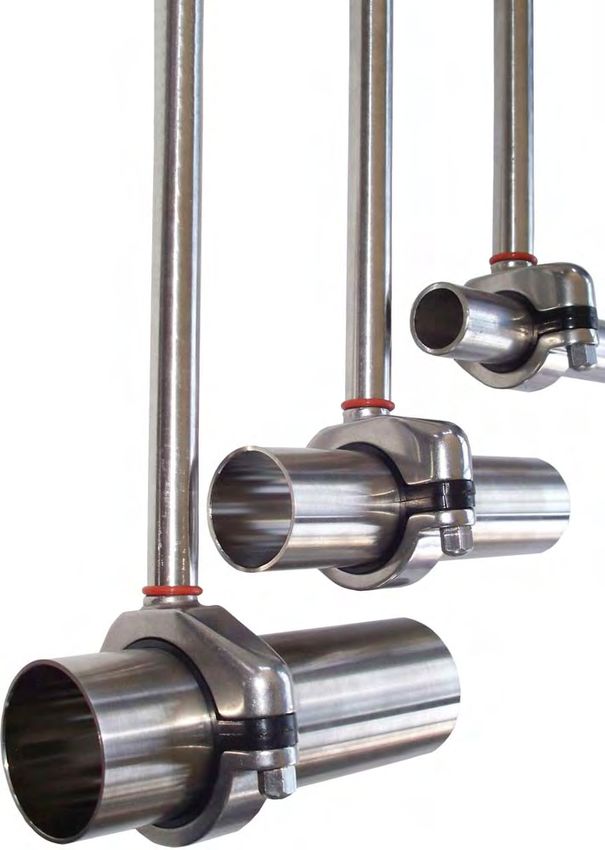
Automatic Slope
                                                          Adjustment
                                              Tension     Ring connection allows hanger
                                              body to     adjust 7” to tube slope and rotate
                                              360” to     relieve all unnecessary stresses
                                              between     tube and CH support

                  Telescopic › Elevation
                      Adjustment
           CH Series with Stanchion allows for quick x, y
              and z axis adjustment for ease in locating
                  tube s direction, elevation and slope.

                                                     One Piece unit
                                                     Assembled as a one piece unit. No
                                                     loose parts, quick identification
                                                     and swift installation. Acorn bolt
                                                     and plastics are captive to the
                                                      CH Housing. (except in Group 9)

                Lot Traceabiity

     Behringer has lot traceability and material
    identification for all stainless steel products.
                (exact locations will vary)

2    Catalog CHSAN1114
                                         PATENT   #D553,971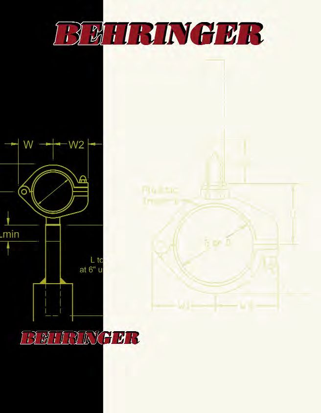
EXAMPLE ORDERING GUIDE

                           fi

                                Catalog CHSAN1114   3
       PATENT   D553,971
fi

PIPE & TUBE SUPPORT
 FIG. 221 CH                                                                          D YNAMIC M OUNT H ANGER
                 Dynamic "Anchor or Guide" Slope Adjusting Hanger / Rod Mount Unit

                One piece unit with attached dynamic rod. Hanger rods are available in
                lengths ranging from min of 1.26" to 96". Standard length is 6”.

                Features: A dynamic union between the hanger rod and hanger housing
                allows for the housing to self adjust to the tube’s slope for drainability as well
                as a 360o swivel. A 6" rod is the standard length with other lengths available.
                Fig 221 CH can also be used in combination with the figure 223, 225 or 226
                stanchions. This combination will allow the support to be adjusted telescopi-
                cally to the tube or pipe elevation. Call customer service for the price and
                availability of special rod lengths.
                Size Range: 0.24" diameters through 6.00" diameter covering imperial tube,
                pipe and copper sizes. ISO and DIN standards, and special diameters avail-
                able upon request.
Housing with                                                                                         Housing with
Black inserts   Hardware: 304 Stainless Steel (Standard), 316 Stainless Steel                        Gray inserts
are "Anchor"                                                                                         are "Guide"
  supports      Finish: Stainless Steel at a 25 RA                                                    supports

                Plastic: Polysulfone (Black = Anchor and Gray = Guide)
                Shearing: Anchors - Refer to shear force diagram in technical section
                                    (page 29)
                          Guides - Allows free axial movement for thermal expansion
                                   of tube or pipe

 4        Catalog CHSAN1114
                                                 PATENT   #D553,971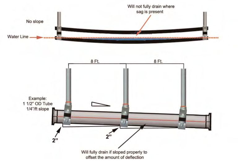
fi

PIPE & TUBE SUPPORT
FIG. 221 CH                                                                            D YNAMIC M OUNT H ANGER

                  All standard sizes shown, special diameters available upon request

                                                                                   Catalog CHSAN1114        5
                                              PATENT   D553,971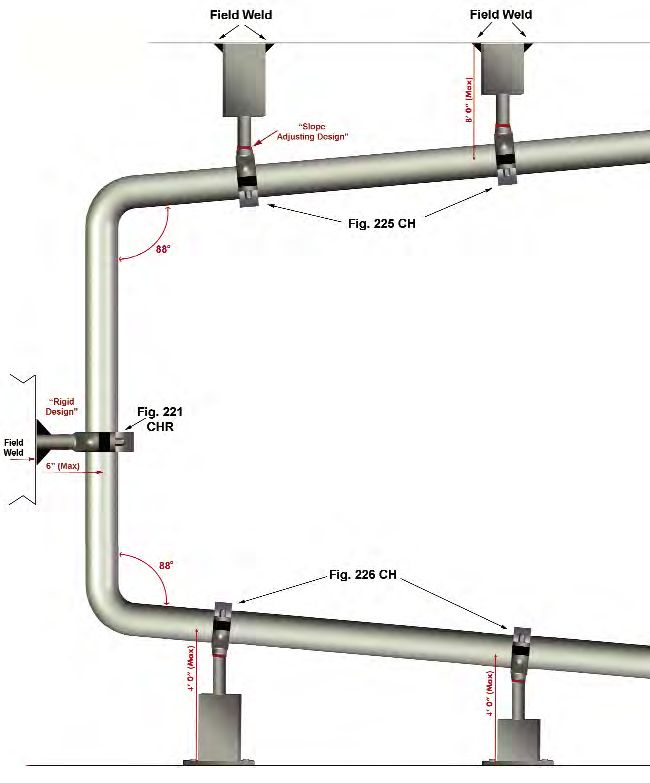
fi

PIPE & TUBE SUPPORT
FIG. 221 CHR                                                                          RIGID M OUNT H ANGER
                             Rigid “Anchor or Guide” Hanger / Rod Mount Unit

                 One piece unit with rod welded to the hanger housing. Hanger rods are
                 available in lengths up to 96”. Standard rod length is 6”
                 Features: The rigid hanger is ideal for supporting vertical runs and reducing
                 vibrations. This type rod connection does not offer the dynamic slope adjust-
                 ment. 6" rod is the standard length with other lengths available. Fig 221
                 CHR can also be used in combination with the figure 223, 225 or 226 stan-
                 chions. This combination will allow the support to be adjusted telescopically to
                 the tube or pipe elevation. Call customer service for the price and availability
                 of special rod lengths.
                 Size Range: 0.24" diameters through 6.00" diameter covering imperial tube,
                 pipe and copper sizes. ISO and DIN standards, and special diameters avail-
                 able upon request.
 Housing with    Hardware: 304 Stainless Steel (Standard), 316 Stainless Steel                      Housing with
 Black inserts                                                                                      Gray inserts
 are "Anchor"    Finish: Stainless steel at a 25 RA                                                 are "Guide"
   supports                                                                                          supports
                 Plastic: Polysulfone (Black = Anchor and Gray = Guide)
                 Shearing: Anchors - Refer to shear force diagram in technical section
                                     (page 29)
                           Guides - Allows free axial movement for thermal expansion
                                     of tube or pipe

6        Catalog CHSAN1114
                                               PATENT   #D553,971
fi
PIPE & TUBE SUPPORT
FIG. 221 CHR RIGID M OUNT H ANGER
All standard sizes shown, special diameters available upon request
Catalog CHSAN1114 7
PATENT D553,971fi
PIPE & TUBE SUPPORT
FIG. 221 CHW W ELD PLATE M OUNT SUPPORT
Rigid “Anchor or Guide” Support with Weld Plate
One piece unit with weld plate attached to hanger housing.
Features: Compact housing is mounted on a weld plate. This type of mounting
configuration does not offer the dynamic slope adjustment feature. The CHW
hanger is ideal for supporting vertical runs and reducing vibrations.
Size Range: 0.24" diameters through 6.00" diameter covering imperial tube,
pipe and copper sizes. ISO and DIN standards and special diameters available
Housing with Housing with
upon request.
Black inserts Gray inserts
are "Anchor" are "Guide"
Hardware: 304 Stainless Steel (Standard), 316 Stainless Steel
supports supports
Finish: Stainless Steel at a 25 RA
Plastic: Polysulfone (Black = Anchor and Gray = Guide)
Shearing: Anchors - Refer to shear force diagram in technical section
(page 29)
Guides - Allows free axial movement for thermal expansion
of tube or pipe
8 Catalog CHSAN1114
PATENT #D553,971fi
PIPE & TUBE SUPPORT
FIG. 221 CHW W ELD PLATE M OUNT SUPPORT
All standard sizes shown, special diameters available upon request
Catalog CHSAN1114 9
PATENT D553,971fi
PIPE & TUBE SUPPORT
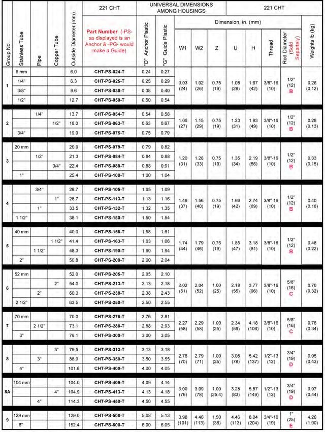
FIG. 221 CHT THREADED M OUNT H ANGER
Threaded Anchor or Guide Hanger
One piece unit with threaded adaptor. Rod is sold separately.
Features: The threaded mounting section, on top of housing, doubles as a
threaded rod connecter and a welding platform. This type rod connection
does not offer the dynamic slope adjustment feature. Figure 221 CHT, with a
rod, can also be used in combination with the figure 223, 225 or 226 stan-
chions. This combination will allow the support to be adjusted telescopically to
the tube or pipe elevation. Call customer service for the price and availability
Housing with of special rod lengths. Housing with
Black inserts Gray inserts
are "Anchor" Size Range: 0.24" diameters through 6.00" diameter covering imperial tube, are "Guide"
supports pipe and copper sizes. ISO and DIN standards, and special diameters avail- supports
able upon request.
Hardware: 304 Stainless Steel (Standard), 316 Stainless Steel
Finish: Stainless steel at a 25 RA
Plastic: Polysulfone (Black = Anchor and Gray = Guide)
Shearing: Anchors - Refer to shear force diagram in technical section
(page 29)
Guides - Allows free axial movement for thermal expansion
of tube or pipe
**See Figure 245 to Order Threaded Rod Separately**
10 Catalog CHSAN1114
PATENT #D553,971fi
PIPE & TUBE SUPPORT
FIG. 221 CHT THREADED M OUNT H ANGER
All standard sizes shown, special diameters available upon request
Catalog CHSAN1114 11
PATENT D553,971fi
PIPE & TUBE SUPPORT
FIG. 245 THREADED SUPPORT ROD
Size Range: 3/8" outside diameter to 1" outside diameter with different rod lengths and connection
threads avialable.
Hardware: 304 Stainless Steel or 316 Stainless Steel; Carbon or Electro-Zinc Plated Carbon Steel
Finish: 25 Ra (for 304/316); Other available upon request
Ordering: To identify the proper thread refer to the "T" column on Fig. 221CHT or the Hang Nut
column on Fig. 201. Then use the Fig 245 part number configuator located at the
bottom of this page.
Installations: Thread the rod into housing. Cut the rod in the field to proper length. Field weld the
rod to support structure. The rod can also be used in combination with the figure
223, 225 or 226 stanchions. This combination will allow the support to be adjusted
telescopically to the tube or pipe elevation.
Fig. 225 Telescopic Rod Adjustment Fig. 226 Telescopic Rod Adjustment
to the tubes elevation to the tubes elevation
12 Catalog CHSAN1114fi
PIPE & TUBE SUPPORT
FIG. 223 TELESCOPIC ADJUSTING ROUND FLOOR M OUNT STAND
The Telescopic Adjusting Round Floor Mount Stand allows the housing’s rod elevation to
be adjusted up to 2” from the base plate’s surface. The rod attached to the housing slides
inside the base plate’s elevation adjustment tube (.560 ID x .750 OD). This fine tune
adjustment allows the installer to quickly change the support’s elevation to match the
tube’s distance from the floor. The base plate can be supplied with or without anchor bolt
holes. Anchor bolts not supplied by Behringer.
Base Plate Sizing: RSP1 & RSP2 - 0.25” to 2.00” OD tube & pipe sizes
RSP3 & RSP4 - 2.05” to 4.50” OD tube & pipe sizes
RSP5 & RSP6 - 5.08” to 6.00” OD tube & pipe sizes
Hardware: 304 Stainless Steel, 316 Stainless Steel, Carbon Steel & Electro-Zinc Plated Carbon Steel
Finish: MILL = Fabricated steel and welds are a mill finish
BUFF = Fabricated steel and weld are buffed to remove splatter
BLND = Fabricated steel is polished and welds are blended
Special finishes and painted stands are available, call Behringer Customer Service
for price and availability.
Clamp & Rod Sold Separately
Catalog CHSAN1114 13
PATENT D553,971fi
PIPE & TUBE SUPPORT
FIG. 224 CH SERIES ROD STAND PLATE
One piece CH Series Rod Stand Plate with rod cut to specified length. The rod is welded to
the base plate, which can be supplied with or without anchor bolt-holes. Anchor bolts not
supplied by Behringer.
The height is calculated from the top of the plate to centerline of tube or pipe. Please refer
to “U” min column in catalog for minimum height of the required RH series product.
Base Plate Sizing: RSP1 & RSP2 - 0.25” to 2.00” OD tube & pipe sizes
RSP3 & RSP4 - 2.05” to 4.50” OD tube & pipe sizes
RSP5 & RSP6 - 5.08” to 6.00” OD tube & pipe sizes
Hardware: 304 Stainless Steel, 316 Stainless Steel
Finish: MILL = Fabricated steel and welds are a mill finish
BUFF = Fabricated steel and weld are buffed to remove splatter
BLND = Fabricated steel is polished and welds are blended
Special finishes and painted stands are available, call Behringer
Customer Service for price and availability.
14 Catalog CHSAN1114
PATENT #D553,971fi
PIPE & TUBE SUPPORT
FIG. 225 TELESCOPIC ADJUSTING STANCHION › HANG M OUNT
Hanger Stanchion with square or round tube cut to specified length. One end of the
tube has a capped end with a rod hole. The rod hole is used for telescopic
adjustment of the hanger rod. Specify the steel finish and the finish on the weld.
Features: Hole in capped end of tube allows the hanger rod to be manually
adjusted for telescopic location of the tube or pipe.
Hardware: 304 Stainless Steel; 316 Stainless Steel, Carbon Steel & Electro-Zinc
Plated Carbon Steel
Finish: MILL = Fabricated steel and welds are a mill finish
BUFF = Fabricated steel and welds are buffed to remove splatter
BLND = Fabricated steel is polished and welds are blended
Special finishes and painted stanchions are available, call Behringer
Customer Service for price and availability.
Square Stanchion Hang Mount Round Stanchion Hang Mount
Catalog CHSAN1114 15fi
PIPE & TUBE SUPPORT
FIG. 226 TELESCOPIC ADJUSTING STANCHION › F
LOOR M OUNT
One piece Floor Stand with square or round tube cut to specified length. One end of the
tube has a capped end with a rod hole. The rod hole is used for telescopic adjustment
of the hanger rod. The open end of the tube is welded to a base plate which can be sup-
plied with or without anchor bolt holes. Specify the steel finish and the finish on the weld.
Features: Hole in capped end of tube allows the hanger rod to be manually
adjusted for telescopic location of the tube or pipe.
Hardware: 304 Stainless Steel; 316 Stainless Steel, Carbon Steel & Electro-
Zinc Plated Carbon Steel
Finish: MILL = Fabricated steel and welds are a mill finish
BUFF = Fabricated steel and welds are buffed to remove splatter
BLND = Fabricated steel is polished and welds are blended
Special finishes and painted stanchions are available, call Behringer
Customer Service for price and availability.
Round Stanchion Floor Mount Square Stanchion Floor Mount
Base plate can be supplied without mounting holes
16 Catalog CHSAN1114fi
PIPE & TUBE SUPPORT
PIPE CLAMP SELECTION
Mounting / Hardware Configuration Rail Mounting [RCN, RAL]
Behringer offers an array of mounting configurations
and arrangement styles for the Sanitary Smooth Bore Rail mounting makes installations of
Series supports. They can be mounted to the support multiple lines of different group sizes
structure by either welding, bolting, hanging, rail an easy task. All clamps within one
mount, strut mount or via stanchions. In addition, they series can be mounted directly to a
can be stacked on top of each other to save on space. single channel using Rail Nuts (RCN)
Please check the ordering code for available assem- or Weld Plates (STW) in conjunction
blies with the configuration you desire. Here are some with Behringer’s proprietary Mounting
examples of the mounting options. Rail (RAL-1).
Weld Mounting [STW] Strut Mounting [UCN]
Clamps are supplied with a weld plate Clamps are supplied with Unistrut Clip
(STW) for welding directly to the support Nuts (UCN) for mounting to standard
structure. This is the most commonly Unistrut channel. The nuts adapt to
used style and includes a cover plate any strut channel that is 1 5/8” wide.
(COP) and hex bolts (HEX). The depth of the channel is not impor-
tant as the UCN clips attach with
spring loaded tension to the top of the
channel.
Hang Mounting [HAP] Stacking Kits [SKSB]
Clamps are supplied with a hang plate Stacking kits consist of a set of Clamp
(HAP) that allows the support block to be Halves (CLH), Stacking Bolts (STB)
installed at a distance from the structural and a Safety Plate (SAF). A stacking kit
member from which it is mounted. They is everything needed to take an exist-
are hung from threaded rod to the ing clamp and add an additional level.
desired elevation. Start by simply using the hardware
from the existing clamp, remove the
cover plate, clamp halves, and hex
bolts and insert the stacking kit onto
the bottom plate and then replace the
Bolt Mounting [BAP] original hardware on top. Multiple
stacking kits can be added to increase
Clamps are supplied with a Base Plate the number of clamps stacked in a
(BAP) for applications where the clamp series.
cannot be welded into position. This is
commonly used to mount to non-metallic
surfaces, such as wood or drywall.
Catalog CHSAN1114 17fi
PIPE & TUBE SUPPORT
H YGIENIC PIPE & TUBE SUPPORTS SANITARY SMOOTH BORE SERIES
Figure 200 Figure 202 Figure 211
Weld Plate Mount Base Plate Mount Unistrut Mount
HEX HEX HEX
COP COP COP
CLH (pair) CLH (pair) CLH (pair)
STW BAP UCN
Figure 201 Figure 204
Hang Plate Mount Rail Mount Stacking Kit
HAP
HEX
CLH (pair)
COP
COP CLH (pair)
SAF
HEX
RCN STB
Key:
BAP - Base Plate SAF - Safety Plate CLH (pair)
CLH - Clamp Half (pair) STB - Stacking Bolt
COP - Cover Plate STW- Standard Weld Plate
HAP - Hang Plate UCN- Unistrut Clip Nut
HEX - Hex Bolt RCN- Rail Nut
18 Catalog CHSAN1114
PATENT #D553,971fi
PIPE & TUBE SUPPORT
FIG. 200 LOCK
B STYLE W ELD PLATE M OUNT
Size Range: 1/4” outside diameter through 8.625” outside diameter
Hardware: 304 Stainless Steel, 316 Stainless Steel, or Electro-Zinc Plated Carbon Steel
Plastic Inserts: Polypropylene (blue)
Santoprene (beige)
Polysulfone (black)
HDPE (white)
High Temp Nylon (black)
*See page 28 for temperature ratings
Installations: Weld bottom plate to structure or supporting member, let cool before mount-
ing plastic blocks.
Thermal Expansion Guide: (Optional) Provides for axial expansion of the tube or pipe due to thermal
expansion. One set of two per clamp (See Fig. 207 in accessories)
Thermal Expansion Guide
Material: Santoprene, 1/16" insert, Black for service identification
Catalog CHSAN1114 19
PATENT D553,971fi
PIPE & TUBE SUPPORT
FIG. 201 H ANG PLATE M OUNT
Size Range: 1/4” outside diameter through 6.625” diameter
Hardware: 304 Stainless Steel, 316 Stainless Steel, or Electro-Zinc Plated Carbon Steel
Plastic Inserts: Polypropylene (blue)
Santoprene (beige)
Polysulfone (black)
HDPE (white)
High Temp Nylon (black)
*See page 28 for temperature ratings
Installations: Hang from threaded rod to desired elevation
Thermal Expansion Guide: (Optional) Provides for axial expansion of the tube or pipe due to thermal
expansion. One set of two per clamp (See Fig. 207 in accessories)
Thermal Expansion Guide
Material: Santoprene, 1/16" insert, Black for service identification
* Also available with a 1/2 - 13 thread
20 Catalog CHSAN1114fi
PIPE & TUBE SUPPORT
FIG. 202 BASE PLATE M OUNT
Size Range: 1/4" outside diameter through 6.625" outside diameter
Hardware: 304 Stainless Steel, 316 Stainless Steel, or Electro-Zinc Plated Carbon Steel
Plastic Insert: Polypropylene (blue)
Santoprene (beige)
Polysulfone (black)
HDPE (white)
High Temp Nylon (black)
*See page 28 for temperature ratings
Installation: Locate bolt holes in mounting structure and either tap into structure or use
1/4-20 bolt and nut to secure
Thermal Expansion Guide: (Optional) Provides for axial expansion of the tube or pipe due to thermal
expansion. One set of two per clamp (See Fig. 207 in accessories)
Thermal Expansion Guide
Santoprene, 1/16" insert, Black for service identification
Material:
Catalog CHSAN1114 21fi
RAIL FOR PIPE AND TUBE SUPPORT
FIG. 203 RAL›1 ARIL M OUNTING
Size Range: Rail Accomodates Clamps from
1/4” through 4” tube
Hardware: 304 Stainless Steel; 316 Stainless Steel;
Electro-Zinc Plated Carbon Steel
Installations: Weld Rail (RAL-1) to structure or supporting
member. Slide clamp weld plate into rail, locate
proper position and assemble clamp. Tightening
hex bolts of clamp will lock clamp into position.
*See Alternate Mounting Option below
*Alternate Mounting Option
RCN-1
Rail Nut (RCN-1) may also be used
when mounting to Behringer’s pro-
prietary mounting rail (RAL-1)
22 Catalog CHSAN1114fi
PIPE & TUBE SUPPORT
FIG. 204 STACKING KIT
Size Range: Any double combination of sizes 1/4” outside diameter through 3.5” outside
diameter
Hardware: 304 Stainless Steel, 316 Stainless Steel, or Electro-Zinc Plated Carbon Steel
Plastic Inserts: Polypropylene (blue)
Santoprene (beige)
Polysulfone (black)
*See page 28 for temperature ratings
Thermal Expansion Guide: (Optional) Provides for axial expansion of the tube or pipe due to thermal
expansion. One set of two per clamp (See Fig. 207 in accessories).
Thermal Expansion Guide
Material: Santoprene, 1/16" insert, Black for service identification
***NOTE: This is sold as a modular component ONLY. Must order Fig. 200, 201 or 202 as
a bottom assembly in addition to each stacking kit.
Catalog CHSAN1114 23fi
PIPE & TUBE SUPPORT
FIG. 211 U NISTRUT M OUNT CLAMP
Size Range: 1/4" outside diameter through 4" outside diameter.
Hardware: 304 Stainless Steel, 316 Stainless Steel, or Electro-Zinc Plated Carbon Steel
Plastic Inserts: Polypropylene (blue)
Santoprene (tan)
Polysulfone (black)
*See page 28 for temperature ratings
Installations: After unistrut rail position has been established, position 2 unistrut rail nuts in
channel where desired to accept plastic inserts. Place pipe or tube in
clamp perpendicular to unistrut channel. Torque down on clamp bolts to
lock assembly in place.
Thermal Expansion Guide: (Optional) Provides for axial expansion of the tube or pipe due to thermal
expansion. One set of two per clamp (See Fig. 207 in accessories).
Thermal Expansion Guide
Material: Santoprene, 1/16" insert, Black for service identification
24 Catalog CHSAN1114fi
PIPE & TUBE SUPPORT
FIG. 221 ROD M OUNT
Size Range: 1/4” outside diameter through 6.625” outside diameter
Hardware: 304 Stainless Steel, 316 Stainless Steel, or Electro-Zinc Plated Carbon Steel
Plastic Inserts: Polypropylene (blue)
Santoprene (beige)
Polysulfone (black)
HDPE (white)
High Temp Nylon (black)
*See page 28 for temperature ratings
Installations: Cut bar in field to proper length. Field weld hang or floor mount bar to sup-
port structure. Fig 221 can also be used in combination with the figure 225
or 226 stanchions. This combination will allow the support to be adjusted
telescopically to the tube or pipe elevation. Call customer
service for the price and availability of special rod lengths.
Thermal Expansion Guide: (Optional) Provides for axial expansion of the tube or pipe due to thermal
expansion. One set of two per clamp. (See Fig. 207 in accessories).
Thermal Expansion Guide
Material: Santoprene, 1/16" insert, Black for service identification
Catalog CHSAN1114 25fi
TECHNICAL APPENDIX
Proper Slope for Drainability
Process piping must be installed to achieve:
• Continuous slope for drainability-offset any deflection present with slope.
• Adequate spacing of supports to avoid pooling of liquids
• Minimum slope per ASME BPE Standard:
• Table SD-2.4.3.1-1 Slope Designations for Gravity-Drained Lines
• GSD1 1
⁄16”/ft. minimum (5mm/m)
• GSD2 1
⁄8”/ft. minimum (10mm/m)
• (min. recommended by ASME for product-contact lines)
• GSD3 1
⁄4”/ft. minimum (20mm/m)
• GSD0 Line slope not required
• Slope measurements should be taken with a calibrated digital level or protractor per ASME
BPE Non-Mandatory Appendix C
• Added support in proximity to any concentrated loads
• Supports at each change of direction
• Corrosion resistance
• Materials compatible with the chemical, thermal, and physical performance requirements of
each application
26 Catalog CHSAN1114fi
SANITARY CLAMPS
TECHNICAL APPENDIX
Recommended Mounting Practices
Bends
Behringer recommends that supports and hangers be
installed in close proximity to each change in direction of pip-
ing, with consideration of pipe movement due to thermal
expansion and use of anchor and guide inserts to facilitate
intended pipe movements.
Concentrated Loads
Behringer recommends that supports and hangers be
installed as close as possible to any concentrated loads,
such as valves, instrumentation, and other process compo-
nents. It may be necessary to install on both sides of certain
loads to reduce deflection and ensure proper continuous
slope for drainability.
Thermal Expansion
• Anchoring systems should be designed to accommodate piping motion including thermal expansion.
• Proper selection and positioning of anchors and guides to facilitate thermal cycling of the piping with out causing
structural damage or cause process components to misalign at mechanical joints.
• Anchor - An anchor is a rigid device used to prevent all pipe displacement at the point of application. Anchors are
used to fix selected points on a piping system in order to control forces, moments, and movement in each
section of the total pipe run.
• Guide - A guide is a device used to permit pipe movement in a predetermined direction while preventing undesirable
movement in other directions. Guides are used to control piping movement, provide lateral pipe stability, con-
trol sway, and ensure proper alignment at expansion joints and loops. The guide allows free axial movement
of the pipe/tube while maintaining proper alignment and elevation for drainability.
• Enlarging the ID dimension of the CH Series Polysulfone insert by .040” (Groups 1-5) and 0.050” (Groups 6-9)
turns a gripping support “Anchor” into a “Guide”. Behringer stocks both anchor and guide inserts for OD tube, pipe,
and copper tube sizes. See part number configuration for more information. Guide inserts are also available for the
Smooth Bore Series (See Fig. 207 in accessories)
Catalog CHSAN1114 27fi
M ATERIALPROPERTIES, T
ECHNICAL D ATA
Metal Parts
› Surface finishing
In addition to the standard surface finish, alternative finishes are available on r
Mill Finish Brushed Blended Weld
28 Catalog CHSAN1114fi
SLOPE CONVERSION CHART, S
HEAR FORCE D IAGRAM
( -- Acorn Bolt Torque 7 Foot - Pounds )
Without Thermal Expansion Guide
Note: Shear Force Testing was conducted under controlled conditions and with manufacturers recommended bolt
torque. Actual Shear Forces may vary due to specific process conditions such as temperature, tube surface
roughness, uneven load conditions and presence of line shock and/or vibration.
Catalog CHSAN1114 29fi
M ATERIALS, MATERIALPROPERTIES,TECHNICAL D ATA
SPACING OF HANGERS
Hangers and/or supports shall be spaced as far apart as economically possible
consideration to assure that the sag of the pipe between supports is within l
permit drainage and also avoid excessive bending stresses from concentrated l
valves and in›line equipment. Contractor shall use the maximum recommended sp
between pipe support specified below. Spacing indicated below may differ from
in MSS SP› 69. Additional hangers may be necessary to adequately support con
loads such as valves, flanges, or instruments.
STEEL PIPE HANGER SPACING:
PIPE SIZE (IN) MAXIMUM SPACING (FT)
1/2" & 3/4" 4
1" 5
1›1/2" & 2" 10
3" 12
4" ›16" 16
COPPER TUBING HANGER SPACING (includes schedule 10 pipe):
TUBING SIZE (IN) MAXIMUM SPACING (FT)
3/8" › 3/4" 6
1" › 1›1/4" 8
1› 1/2" › 3" 10
4" › 8" 12
STAINLESS STEEL SANITARY TUBING HANGER SPACING:
TUBING SIZE (IN) MAXIMUM SPACING (FT)
1/2" › 3/4" 4
1" 5
1›1/2" 6
2" 8
2›1/2 › 3" 10
4" 12
6" 14
PLASTIC PIPING:
Support in accordance with manufacturer s recommendations.
30 Catalog CHSAN1114fi
Also available from Behringer Corporation
Industrial Pipe Clamps
Standard Series Pipe Clamps
Range: ¼” OD to 4” OD
Pressure: 2,000 psi max.
Heavy Series Pipe Clamps
Range: ¼” OD to 8” Pipe
Pressure: 5,000 psi max. (Single plate)
10,000 psi max. (Double plate)
Twin Series Pipe Clamps
Range: ¼” OD to 1.66” OD
Pressure: 1,500 psi max.
Heavy 4 Series Pipe Clamps
Range: 8” Pipe to 30” Pipe
Pressure: 5,000 psi max. (Single plate)
10,000 psi max. (Double plate)
Catalog CHSAN1114 iii®
Your Local Stocking Distributor:
®
Catalog CHSAN1114
#You can also read