LEICHTmount RAIL 2.0 S - Flat roof system for south-facing orientation Assembly Instructions - S:FLEX
←
→
Page content transcription
If your browser does not render page correctly, please read the page content below
Photovoltaic Fastening Systems

                      Assembly Instructions

   LEICHTmount RAIL 2.0 S
Flat roof system for south-facing orientation

       © S:FLEX GmbH 01/2021/ Technical changes reserved   1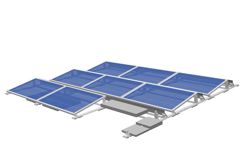
Table of contents

           1            Introduction

                        1.1       Intended use                                                                        3

                        1.2       About this document                                                                 3

                        1.3       Warnings                                                                            4

                        1.4       General information — standards and guidelines                                      4

                        1.5       Description of the system                                                           6

           2            Assembly – LEICHTmount RAIL 2.0 S

                        2.1       System components                                                                  11

                        2.2       Installation – ground rail                                                         12

                        2.3       Installation – tower and tower windshield                                          13

                        2.4       Installation – roll-bar                                                            14

                        2.5       Ballast                                                                            15

                        2.6       Optional roof fastening – assembly post                                            18

                        2.7       Module assembly                                                                    21

                        2.8       Windshield                                                                         25

                        2.9       Covering cable duct                                                                26

                        2.10      Side plate                                                                         27

                        2.11      Final inspection                                                                   28

           3            Disassembly and disposal

                        3.1       Disassembly                                                                        29

                        3.2       Disposal                                                                           29

           4            Terms of use and warranty

                        4.1       User agreement for the LEICHTmount RAIL 2.0 S                                      30

                        4.2       Warranty / disclaimer                                                              30

S:FLEX GmbH • Reinbeker Weg 9 21029 Hamburg Tel. +49 (0)40 688 93 17 0 • Elsässer Str. 12 79189 Bad Krozingen Tel. +49 (0)761 888 56 08 0

info@sflex.com      www.sflex.com                                      © S:FLEX GmbH 01/2021/ Subject to technical modifications            2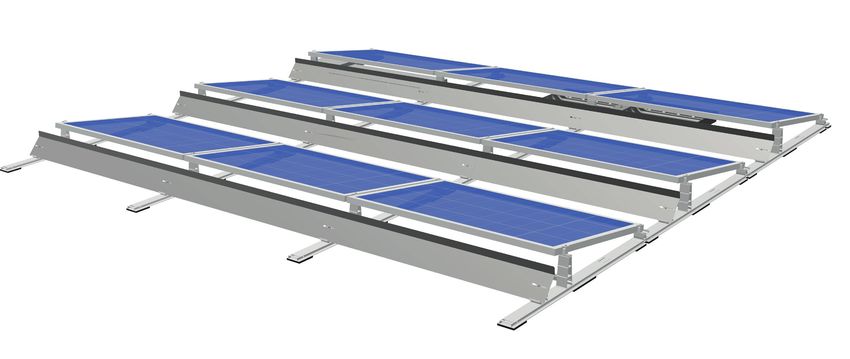
1       Introduction

Read these installation guidelines carefully before installing the S:FLEX mounting system and retain them for future
reference!
These installation guidelines are only complete with the project-specific implementation plans (project report)!

1.1    Intended use

The S:FLEX PV mounting system LEICHTmount RAIL 2.0 S is a rack system for mounting PV modules without roof
penetration.
It is designed exclusively for the installation of PV modules.
The LEICHTmount RAIL S 2.0 is designed for the installation of south-facing systems with module pitch angles of 10°
or 15°.
The system is configured for horizontal module installation.
The adjustable components allow the use of almost all commercially available modules.
The LEICHTmount RAIL 2.0 S system is designed for easy installation on the following substrates:
Foil roofs, bitumen roofs, gravel roofs, green roofs, concrete roofs, sheet metal roofs

Any other use in this regard is considered misuse of the product. In particular, compliance with the instructions in
these installation guidelines constitutes intended use. S:FLEX GmbH accepts no liability for damage resulting from non-
observance of the installation guidelines or from misuse or incorrect use of the product.

1.2    About this document

This installation guide describes the installation of the LEICHTmount RAIL 2.0 S system on flat roofs with a pitch angle
of 10°.

It must be ensured that only current and complete installation guides are used for the installation process.

S:FLEX GmbH • Reinbeker Weg 9 21029 Hamburg Tel. +49 (0)40 688 93 17 0 • Elsässer Str. 12 79189 Bad Krozingen Tel. +49 (0)761 888 56 08 0

info@sflex.com      www.sflex.com                                      © S:FLEX GmbH 01/2021/ Subject to technical modifications            3
1       Introduction

1.3    Warnings

The warning texts provided in these installation guidelines relay safety-related information.
They are:

                 Unless observed, there is a major risk of
                 injury as well as a risk of death.

                 Failure to observe this may lead to
                 property damage.

1.4 General information – standards and guidelines

Every photovoltaic system must be installed in accordance with the instructions contained in the respective installation
guidelines and the project report.
These installation instructions are based on state-of-the-art technology and many years of experience of installing
our systems on site. It must be ensured that only the current and complete installation instructions are used for the
installation, and that a print-out of the installation guidelines is stored in the immediate vicinity of the system. The
system and these guidelines are subject to technical changes.

The project report is part of the installation instructions and is created on a project-specific basis. All of the information
contained in the project report must be strictly observed. The project report contains the location-based static calculations.
The S:FLEX mounting system must be designed and created with the S:FLEX software (Solar.Pro.Tool).

Since individual project-specific features must be considered with every roof, expert advice must always be sought prior
to installation. Before installation, the PV system creator must ensure that the existing roofing and roof substructure
are suitable for the additional loads. The condition of the roof substructure, the quality of the roof covering and the
maximum load-bearing capacity of the roof construction must be checked by the system creator.
Contact a local structural engineer for this purpose.

When installing the PV system, always comply with the module manufacturer’s installation instructions. In particular, it
is necessary to check that the module manufacturer’s instructions regarding the module clamping guidelines (module
clamping surface and clamping range) are complied with. If this is not the case, the customer must obtain a declaration
of consent from the module manufacturer before the installation; alternatively, the mounting system must be adapted
in accordance with the module manufacturer’s specifications.

The requirements for the protection of PV mounting systems against lightning and surges must be met in accordance
with the DIN and VDE regulations. The specifications of the relevant power supply company must be observed.

S:FLEX GmbH • Reinbeker Weg 9 21029 Hamburg Tel. +49 (0)40 688 93 17 0 • Elsässer Str. 12 79189 Bad Krozingen Tel. +49 (0)761 888 56 08 0

info@sflex.com      www.sflex.com                                      © S:FLEX GmbH 01/2021/ Subject to technical modifications            4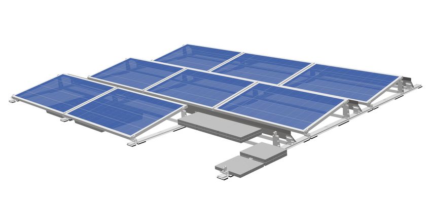
1       Introduction

Care must be taken that the PV system to be installed does not impair the functioning of the existing lightning protection
system. It is also important to ensure that the PV system is designed so that it can be included in the protection zone of
the building's lightning protection system. The separation distances between the PV system and the lightning protection
system specified in the relevant regulations must be adhered to. During installation, the local fire regulations must be
observed, e.g. firewalls must not built over and the required clearances must be maintained.

If the roofing is altered, the manufacturer’s guidelines must be observed. During and after installation, the frame
components may not be stepped on or be used as a climbing aid. There is a risk of falling and the roofing underneath
could be damaged.

Prior to installation, the creator of the photovoltaic system must ensure that the installation is carried out while strictly
adhering to national and location-specific building regulations, safety and accident prevention regulations, standards
and environmental protection regulations.

Every person who installs the S:FLEX PV mounting systems is obligated to independently inform himself/herself about
all rules and regulations for professionally correct planning and installation, and to comply with said rules and regula-
tions during the installation process. This also includes compliance with the latest versions of the respective rules and
regulations.
Installation of the PV system may only be carried out by trained specialists.

                    All system components must be checked for damage before installation.
                    Damaged components must not be used!

                    Installation of the S:FLEX substructure and the PV system may only be carried out by trained
                    specialists. System components must not be used as step ladders. The modules must not be
                    stepped on. When working on roofs, there is a risk of falling off and falling through roofs. A fall can
                    result in injury or death. Ensure that appropriate climbing aids and fall-protection equipment (e.g.
                    scaffolding) are provided as well as protection from falling parts.

                    Check the building statics and construction/condition of the roof substructure before starting the
                    installation. During installation, the instructions in the installation guidelines and project report
                    must be strictly observed. Failure to observe the installation guidelines and the project report may
                    result in damage to the PV system and to the building.

S:FLEX GmbH • Reinbeker Weg 9 21029 Hamburg Tel. +49 (0)40 688 93 17 0 • Elsässer Str. 12 79189 Bad Krozingen Tel. +49 (0)761 888 56 08 0

info@sflex.com      www.sflex.com                                      © S:FLEX GmbH 01/2021/ Subject to technical modifications            5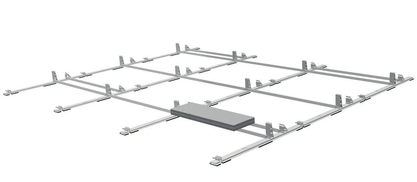
1 Introduction
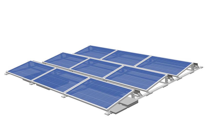
1.5 Description of the system
The LEICHTmount RAIL 2.0 S system includes solutions to suit a range of different requirements:
System properties
Mounting angle: the LEICHTmount 2.0 S is available with 10° and 15° mounting angles
Roof edge spacing: Roof areas F and G can be used
Module dimensions: S 10°: 990 – 1.068mm x 1.614 – 2.172mm (width x length)
S 15°: 990 – 1.068mm x 1.614 – 2.172mm (width x length)
The use of modules with deviating dimensions must be checked and approved for each project.
Max. roof pitch: 5°
Building height: max. 25 m (greater building heights up to 50 m on request)
Wind load: up to 2.4 KN/m2
Snow load: up to 5.4 KN/m2
Modules: The modules are fitted to the short side. Only solar modules with general approvals
or project-related approvals from module manufacturers regarding the clamping to the
short side may be used.
Materials: extruded aluminium EN AW-6060 T66 and stainless steel A2-70
Prerequisites: Proof of static load capacity of the roof and the roof insulation must be provided by customer.
Our general terms and conditions, warranty conditions and the user agreement apply.
The module manufacturer's installation instructions must always be observed.
Flat-roof coverings
The LEICHTmount RAIL 2.0 E/W can be installed on the following flat roof coverings foil roof, bitumen roof, gravel roof,
green roof, concrete roof, sheet metal roof
The compatibility of the roof covering and PE protective mat must be ensured.
The roof covering (and possible insulation layer) must be able to absorb the pressure loads of the PV system.
For mineral wool as insulation material, the compressive strength must be at least 70kPa at 10% compression, a load-
distributing layer must be arranged above the insulation and the manufacturer’s approval must be available.
The friction coefficient of the existing roof covering is the basis of the ballasting plan and must be determined by the customer.
For installation on gravelled roofs, a protective layer is prescribed between the water-bearing roof cladding and the
gravel fill. The gravel fill must have a minimum depth of 50mm and a grain size of 16/32.
S:FLEX GmbH may provide a measuring device in order to determine the project-specific friction
coefficient.
S:FLEX GmbH • Reinbeker Weg 9 21029 Hamburg Tel. +49 (0)40 688 93 17 0 • Elsässer Str. 12 79189 Bad Krozingen Tel. +49 (0)761 888 56 08 0
info@sflex.com www.sflex.com © S:FLEX GmbH 01/2021/ Subject to technical modifications 6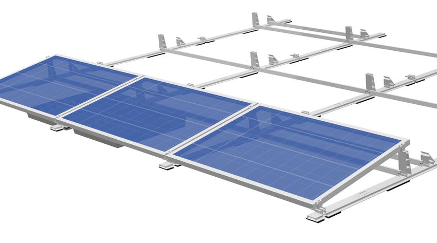
1      Introduction

                                 Row spacings

                                 LEICHTmount RAIL 2.0 S 10°

                                                                                       468,6
                              286,5

                                                                                             204

                                                                1467                                                                      1467                                  1467

                                  In the standard version, the ground rails are fitted with 3-piece PE protective mats. For better absorption and distribution
                                  of the pressure loads, there are other variants, which are fitted with additional PE protective mats.

                                  Option 1: Standard fitting of PE protective mats (565.80 cm²/ground rail)
                                                                                                1467
                                                                        487,8                                            487,8
                                               115

                                                          123                                      246                                         123

                                  Option 2: Additional fitting of PE protective mats (990.15 cm²/ground rail)
                                                                                                 1467
                                                                151,7                    151,7           151,7                   151,7
                                                115

                                                          123                 246                  123                   246                   123

                                  Option 3: Maximum fitting of PE protective mats (1,414.5 cm²/ground rail)
                                                                                                 1467
                                                                40               40      38,8                 40     38,8                 40
                                                115

                                                          123         246              123         246             123         246             123
pyright S:FLEX GmbH 2018
S:FLEX GmbH 2018

                           Anmerkung                             Allgemeintoleranz               Oberfläche                      Werkstoff              Gewicht

                                                                 DIN ISO 2768-1 m                pressblank
                                 S:FLEX GmbH • Reinbeker Weg 9 21029 Hamburg Tel. +49 (0)40 688 93 17 0 • Elsässer Str. 12 79189 Bad Krozingen Tel. +49 (0)761 888 56 08 0
                            Anmerkung
                                 info@sflex.com
                                                                 Artikelbezeichnung
                                                      www.sflex.com
                                                                   Allgemeintoleranz               Oberfläche
                                                                                                                                 Erstellt durch
                                                                                                                                   Werkstoff
                                                                                                                                                        Genehmigt von
                                                                                                                                     © S:FLEX GmbHGewicht
                                                                                                                                                    01/2021/ Subject to technical modifications   7
                                                               DIN ISO 2768-1 m                    pressblank
                                                                 Artikelnummer                                                   Status      Änderung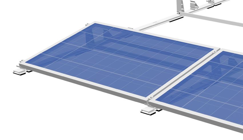
1       Introduction

  Installation note regarding module widths

  The S:FLEX LEICHTmount RAIL 2.0 S 10° system is suitable for mounting modules with a width between 990 and
  1.068mm. Different brackets (base) are used for the modules:

           - Module width 990 - 1.020mm: LmR 2.0 Base 10°
           - Module width 1.021 - 1.068mm: LmR 2.0 Base M6 10°

  Basic conditions for the module field size

  The S:FLEX LEICHTmount RAIL 2.0 S system allows a variable module arrangement. This allows optimal
  utilisation of the roof area. In principle, the module layout should always be based on the module arrangement
  specified in the project report.
                                                            13 rows

                        12 modules

Maximum module array size 10°: 13 rows with 12 modules (156 modules).

  S:FLEX GmbH • Reinbeker Weg 9 21029 Hamburg Tel. +49 (0)40 688 93 17 0 • Elsässer Str. 12 79189 Bad Krozingen Tel. +49 (0)761 888 56 08 0

  info@sflex.com      www.sflex.com                                      © S:FLEX GmbH 01/2021/ Subject to technical modifications            8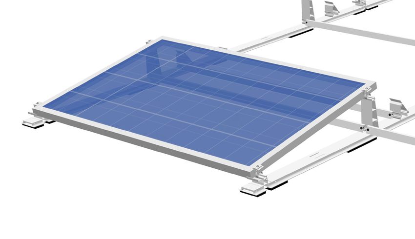
1 Introduction
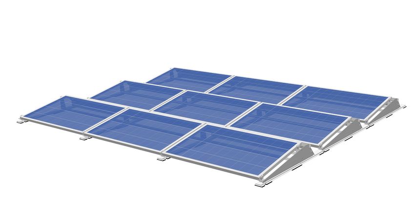
System design
LEICHTmount RAIL 2.0 S
The standard system is suitable for regular wind and snow loads. All values in the project report are design values as
a combined load of dead weight, wind and snow pressure. This information should be used as a rough guide only. The
information in the project report always takes priority!
Therefore, first determine the snow and wind load zone in which the system will be used.
Ballaststein
Windleitblech
Bodenschiene Typ 75 Tower
Base
Bodenschiene mit Base
PE-Schutzmatte
Windshield
Mid clamps
Tower
End clamp
Ballast tray
Roll-bar
Ballast block
S:FLEX GmbH • Reinbeker Weg 9 21029 Hamburg Tel. +49 (0)40 688 93 17 0 • Elsässer Str. 12 79189 Bad Krozingen Tel. +49 (0)761 888 56 08 0
info@sflex.com www.sflex.com © S:FLEX GmbH 01/2021/ Subject to technical modifications 9
1       Introduction

Earthing

Equipotential bonding between the individual system components must be ensured according to the respective country-
specific guidelines and standards. This installation recommendation does not include an earthing concept and must be
calculated or compiled by the executing installer in accordance with the applicable standards and guidelines.

                                                                               =
          Grounding plate

Module earthing via mid clamp with grounding plate

The requirements for the protection of PV mounting systems against lightning and surges must be met in accordance
with the applicable regulations. The specifications of the responsible energy supply company must be observed. The
LEICHTmount Rail EW mounting system is capable of carrying lightning current in accordance with DIN EN 62561-1:
2017-12 and can be integrated into the existing or planned lightning protection system.

                 The module manufacturer's installation instructions must always be observed.

                    The requirements for lightning and surge protection of mounting systems for PV systems
                    must be met in accordance with the applicable regulations.
                    The planning and execution of all lightning protection work may only be carried out by appropriately
                    qualified lightning protection specialists.

S:FLEX GmbH • Reinbeker Weg 9 21029 Hamburg Tel. +49 (0)40 688 93 17 0 • Elsässer Str. 12 79189 Bad Krozingen Tel. +49 (0)761 888 56 08 0

info@sflex.com      www.sflex.com                                      © S:FLEX GmbH 01/2021/ Subject to technical modifications            10
2 Assembly – LEICHTmount RAIL 2.0 S
2.1 System components
1 System components
Ground rail type 75 Assembly post Connector USO S
(PVC, bitumen or
bright stainless
steel)
Ground rail base Covering (PVC or
bitumen)
2 Base 3 Tower
Base Tower Tower windshield
4 Roll-bar 5 Splice for roll-bar 6 Windshield
Roll-bar Splice for roll-bar Windshield
7 End clamp 8 Mid clamps 9 Clip windshield
EH AK II Klick 30-50 MH AK II Klick 30-50 A Clip windshield
MH AK II Klick 30-50 A grounding plate
10 Screw OMG HD 11 Ballast tray 12 Ballast block (optional)
Screw OMG HD Ballast tray Ballast block
13 Covering cable duct 14 Side panel
Covering cable duct Side panel
S:FLEX GmbH • Reinbeker Weg 9 21029 Hamburg Tel. +49 (0)40 688 93 17 0 • Elsässer Str. 12 79189 Bad Krozingen Tel. +49 (0)761 888 56 08 0
info@sflex.com www.sflex.com © S:FLEX GmbH 01/2021/ Subject to technical modifications 112 Assembly – LEICHTmount RAIL 2.0 S
Frame
2.2 Installation – ground rail
The design and planning of the LEICHTmount system must be undertaken using the S:FLEX
Planning Software (Solar.Pro.Tool). Please make sure that the position of the modules on the roof
and the ballast distribution correspond exactly to the specifications in the project report.
If the module distribution on the roof is changed due to local circumstances, such as interfering
surfaces, the static calculation must be repeated using the S:FLEX planning software (Solar.Pro.
Tool).
Do not leave the installation site until the ballast for each module has been installed in accordance
with the ballast chart. Without the ballast, the stability of the module array is not guaranteed.
The correct position of the ballast blocks and building screen mats should be checked as part of
the annual maintenance inspection. It is the responsibility of the installing company to check the
specification and weight of the required ballast blocks.
x = module length minus 95 mm*
*
x plus 20mm (width of module holder) minus 115mm (width of ground rail) = minus
95mm
All ground rails are provided with an 11 mm thick high-tech protective foam mat. This ensures a free water drainage
and prevents damage to the roof covering due to mechanical impacts and long-term damage from plasticiser migration.
Preparatory work:
Clean the roof surface and clear it of obstructive objects. Measure the roof surface and compare it with planning
documents. Draw the system dimensions.
Procedure:
The ground rails must be positioned one after the other as specified in the planning documents. The positioning of the
ground rail must always start at the edge (on the northern or southern side) of the module field. To facilitate adjustment
of the rail installation, the side on which more than one (or all) module rows are flush. The sequence is the same for
each row and always ends at the end of the row with a ground rail base. Slide the ground rails into each other until they
click into place with an audible click (see picture below). Check that the click connection is a clean form fit and securely
fixed. The ground rail rows must be aligned at the distance specified in the planning documentation. If necessary, use
the assembly jigs.
The base must always be positioned with the module installation attachment facing away from the
ground rail.
S:FLEX GmbH • Reinbeker Weg 9 21029 Hamburg Tel. +49 (0)40 688 93 17 0 • Elsässer Str. 12 79189 Bad Krozingen Tel. +49 (0)761 888 56 08 0
info@sflex.com www.sflex.com © S:FLEX GmbH 01/2021/ Subject to technical modifications 122 Assembly – LEICHTmount RAIL 2.0 S
Frame
2.3 Installation – tower and tower windshield
The tower is used as a supporting element for the modules.
Procedure:
The tower must be inserted into the narrow recesses of the ground rail with both suspension hooks, and pushed
sideways until it audibly clicks into place. Check that the click connection is a clean form fit and securely fixed.
Correct Incorrect
S:FLEX GmbH • Reinbeker Weg 9 21029 Hamburg Tel. +49 (0)40 688 93 17 0 • Elsässer Str. 12 79189 Bad Krozingen Tel. +49 (0)761 888 56 08 0
info@sflex.com www.sflex.com © S:FLEX GmbH 01/2021/ Subject to technical modifications 132 Assembly – LEICHTmount RAIL 2.0 S
Frame
2.4 Installation – roll-bar Module length roll-bar✴
1.614 - 1.639 mm Type 1614
1.640 - 1.665 mm Type 1648
1.666 - 1.700 mm Type 1682
1.701 - 1.733 mm Type 1717
1.734 - 1.776 mm Type 1752
1.777 - 1.812 mm Type 1787
1.813 - 1.846 mm Type 1832
1.847 - 1.879 mm Type 1865
1.950 - 1.977 mm Type 1962
1.978 - 2.005 mm Type 1990
2.006 - 2.033 mm Type 2017
2.057 - 2.075 mm Type 2067
2.090 - 2.117 mm Type 2102
2.118 - 2.144 mm Type 2130
2.145 - 2.176 mm Type 2162
✴
roll-bar in other lengths on request
The roll-bars have two functions. Firstly, they raise the static part of the system and facilitate further work like placing
the cables and positioning the modules, because the ground rails can no longer move out of place. Secondly, they are
used to hold additional ballast.
Roll-bar
5 mm
min. 1
Procedure:
Mount the roll-bar onto the tower using the hook-in catch and fasten together using the ISO 7380 M8x30 screws,
tightening as far as they will go (torque 8-10 Nm).
Splice for roll-bar
Procedure:
Install the splice for the roll-bar in strict accordance with the planning documents. Slide the splice into the roll-bar up to
the middle. Slide the next roll-bar over the splice and fasten together using the ISO 7380 A2 M8x30 screws, tightening
as far as they will go (torque 8-10 Nm).
S:FLEX GmbH • Reinbeker Weg 9 21029 Hamburg Tel. +49 (0)40 688 93 17 0 • Elsässer Str. 12 79189 Bad Krozingen Tel. +49 (0)761 888 56 08 0
info@sflex.com www.sflex.com © S:FLEX GmbH 01/2021/ Subject to technical modifications 142 Assembly – LEICHTmount RAIL 2.0 S
Ballast
2.5 Ballast
In general, additional ballast is required to prevent the PV system from lifting, moving or slipping. The quantity and
distribution of the ballast depend on parameters such as location, building height, building surroundings, roofing type
and roof pitch. This information is included in the planning documents.
Suitable ballast block dimensions: 40cm x 40cm x 4cm
Option 1 – Ballast Block Type 1
Procedure:
Install the ballast onto the ground rail directly next to the tower according to the planning documents.
The position of the ballasting must always be carried out in strict adherence to the planning
documents. A different distribution or omission of ballast elements endangers the stability of the
entire plant and represents an enormous risk. The position of the ballasting elements must be
chosen so that slipping down, tipping or wobbling are prevented. The ballast must lie completely
flat. It is insufficient to merely lean the ballast.
S:FLEX GmbH • Reinbeker Weg 9 21029 Hamburg Tel. +49 (0)40 688 93 17 0 • Elsässer Str. 12 79189 Bad Krozingen Tel. +49 (0)761 888 56 08 0
info@sflex.com www.sflex.com © S:FLEX GmbH 01/2021/ Subject to technical modifications 152 Assembly – LEICHTmount RAIL 2.0 S
Ballast
Option 2 – Ballast Block Type 2
Procedure:
Attach the roll-bar on both sides of the tower as described in step 2.4. Position the ballast on the paired roll-bars
according to the planning documents (maximum weight per ballast support: 135 kg).
The position of the ballasting must always be carried out in strict adherence to the planning
documents. A different distribution or omission of ballast elements endangers the stability of the
entire plant and represents an enormous risk. The position of the ballasting elements must be
chosen so that slipping down, tipping or wobbling are prevented. The ballast must lie completely
flat. It is insufficient to merely lean the ballast.
S:FLEX GmbH • Reinbeker Weg 9 21029 Hamburg Tel. +49 (0)40 688 93 17 0 • Elsässer Str. 12 79189 Bad Krozingen Tel. +49 (0)761 888 56 08 0
info@sflex.com www.sflex.com © S:FLEX GmbH 01/2021/ Subject to technical modifications 162 Assembly – LEICHTmount RAIL 2.0 S
Ballast
Option 3 – Ballast Tray
Not all roof surfaces have additional load reserves for the required ballast locations. In particular, roofs with additional
ballast such as gravel or substrate are often not able to take on additional loads. In order to use these roofs, ballast
trays are used.
6x
Remove gravel/substrate layer up to the inner edges of the ground rails. The depth of the cleared area over the entire
surface should be 50mm from the top edge to guarantee a flat surface for the ballast tray on the remaining layer or
roof surface.
If placing the ballast tray directly on the roof covering, ensure that the substrate is clean to avoid long-term damage
caused by underlying objects between the ballast tray and the roof skin.
Procedure:
Place the ballast tray centrally on the ground rail between the base and the tower. Align adjacent ballast trays correctly
and ensure that the screws are sufficiently attached to the ground rail.
Fasten the ballast tray onto the ground rail using thin sheet metal screws 4.8x19. Use six screws per side, ensuring they
are centred and evenly distributed (maximum torque 5 Nm).
Put ballast back in the ballast tray. Ensure even coverage in the ballast tray.
Ensure minimum coverage in the tray is met according to the planning documents!
S:FLEX GmbH • Reinbeker Weg 9 21029 Hamburg Tel. +49 (0)40 688 93 17 0 • Elsässer Str. 12 79189 Bad Krozingen Tel. +49 (0)761 888 56 08 0
info@sflex.com www.sflex.com © S:FLEX GmbH 01/2021/ Subject to technical modifications 172 Assembly – LEICHTmount RAIL 2.0 S
Assembly post
2.6 Optional roof fastening – assembly post
The assembly post offers the possibility of an additional optional connection of the PV system to the roof substructure.
The use of assembly posts extends the mounting possibilities in situations with additional requirements, such as a roof
pitch greater than 2.5°, or for buildings with low load reserves or high wind loads.
The number and position of the assembly posts can be found in the project report.
The connection to the roof substructure requires roof penetration with up to 6 screws per assembly post. The installation
of the assembly posts and the professional sealing of the roof cladding must be carried out by an appropriate specialist
(roofing) company.
The assembly posts must be installed as the first step before installing the LEICHTmount Rail mounting system!
Mounting sequence: Assembly posts → ground rails (see p.12 of these installation instructions)
Prerequisite:
The thickness of the insulation boards / insulation layer must not exceed 120mm.
For trapezoidal steel roofs (UK), the trapezoidal profiles must have a nominal thickness of at least 0.75 mm.
For concrete roofs, the concrete thickness must be at least 100mm.
The assembly post is available in 3 variants:
- With bitumen primer and bitumen covering for flaming (for bitumen roofs)
- With PVC primer and PVC covering for hot-air bonding (for PVC roofs)
- Pure stainless steel, e.g. for processing with liquid plastic (for other roof coverings)
The assembly post is supplied without cleaner, adhesive or liquid plastic for processing. The selection of the processing
materials and the compatibility tests with the roof covering are the responsibility of the installer.
The quantity and position of the assembly posts must always be determined in strict adherence
to the planning documents. A different distribution or omission of assembly posts endangers the
stability of the entire plant and represents an enormous risk.
The installation must be carried out by a specialist company.
Improper installation of the assembly posts may lead to damage to the roof covering, moisture
entering the roof and permanent damage.
S:FLEX GmbH • Reinbeker Weg 9 21029 Hamburg Tel. +49 (0)40 688 93 17 0 • Elsässer Str. 12 79189 Bad Krozingen Tel. +49 (0)761 888 56 08 0
info@sflex.com www.sflex.com © S:FLEX GmbH 01/2021/ Subject to technical modifications 182 Assembly – LEICHTmount RAIL 2.0 S
Assembly post
Installation diagram for assembly post on trapezoidal sheet metal (also applies for foil/PVC roof)
Select and mark the position of the assembly post in accordance with
the project report.
Clean the mounting surface, approx. 60x60 cm (assembly post: 30x30
cm; covering: 50x50 cm).
Position the assembly post and screw it into the roof substructure with
the appropriate screws OMG HD. The screw connection is established in
the raised corrugations of the trapezoidal substructure.
Then place the covering on top and
glue it flat to the assembly post and to
the roof cladding on all sides.
After positioning the assembly posts, the mounting system is set up and connected to the mounting feet in the next
step.
This step should be carried out before mounting the module!
For mounting on trapezoidal sheet metal, 6 OMG HD roofing screws (6.7x150mm) are required
per mounting foot. The thickness of the insulation layer must not exceed 120mm. The trapezoidal
steel profiles must have a nominal sheet thickness of at least 0.75 mm.
For mounting on concrete roofs, 6 OMG HD (6.3 mm) roof screws are required per mounting foot.
The concrete must be at least 100 mm thick. Installation diagram as shown.
S:FLEX GmbH • Reinbeker Weg 9 21029 Hamburg Tel. +49 (0)40 688 93 17 0 • Elsässer Str. 12 79189 Bad Krozingen Tel. +49 (0)761 888 56 08 0
info@sflex.com www.sflex.com © S:FLEX GmbH 01/2021/ Subject to technical modifications 192 Assembly – LEICHTmount RAIL 2.0 S
Assembly post
The LEICHTmount Rail EW mounting system and the assembly posts are connected using the connector USO S. This is
screwed onto the threaded bolt of the assembly post and bolted laterally with 2 roll-bars.
Attachment to the assembly post:
Windshield
Tower
Ground rail Connector USO S Assembly post
Roll-bar
Screw the first M12 locking nut with the flange facing upwards onto the thread of the assembly post and rotate the nut
loosely downwards. Place the connector USO S with the round hole onto the thread. Screw the second M12 locking nut
with the flange facing downwards onto the thread of the assembly post and rotate the nut loosely downwards.
Align the height of the connector USO S to match the roll-bars (upper edges should be flush). The bevelled side of
the connector USO S is attached to the roll-bar on the side of the windshield. The connectors USO S are now laterally
screwed to the roll-bars with 3 thin sheet metal screws 4.5 x 25 each. Then tighten the M12 locking nuts (tightening
torque: 25–30 Nm).
S:FLEX GmbH • Reinbeker Weg 9 21029 Hamburg Tel. +49 (0)40 688 93 17 0 • Elsässer Str. 12 79189 Bad Krozingen Tel. +49 (0)761 888 56 08 0
info@sflex.com www.sflex.com © S:FLEX GmbH 01/2021/ Subject to technical modifications 202 Assembly – LEICHTmount RAIL 2.0 S
Module assembly
2.7 Module assembly (end clamps)
Place the module on the tower and base. Install the end clamps. To do this, click the end clamp onto the tower and base
and push it onto the module. Ensure that the end clamp is clicked onto both sides on the tower and base.
Now adjust the end clamp to match the height of the module and tighten the screw (torque 8-10 Nm). Ensure that the
end clamp clamps the module frame at the clamping area defined by the module manufacturer.
Snap in the end clamp...
Install the end clamp Push in and tighten
Defined clamping area Incorrect Both sides clicked in Incorrect
Observe the module manufacturer's
Check that the end clamp instructions:
has been clicked in Check the defined clamping area
S:FLEX GmbH • Reinbeker Weg 9 21029 Hamburg Tel. +49 (0)40 688 93 17 0 • Elsässer Str. 12 79189 Bad Krozingen Tel. +49 (0)761 888 56 08 0
info@sflex.com www.sflex.com © S:FLEX GmbH 01/2021/ Subject to technical modifications 212 Assembly – LEICHTmount RAIL 2.0 S
Module assembly
Module installation (mid clamps)
Now install the mid clamps. To do this, click the mid clamp onto the tower and base and push it onto the module. Ensure
that the module mid clamp is clicked onto both sides on the tower and base.
Click mid clamp and push in
Now push the next module under the mid clamp, adjust the mid clamp to the height of the module frame
and tighten the screw (torque 8-10 Nm).
Slide module underneath and
tighten mid clamp
Install mid clamp
S:FLEX GmbH • Reinbeker Weg 9 21029 Hamburg Tel. +49 (0)40 688 93 17 0 • Elsässer Str. 12 79189 Bad Krozingen Tel. +49 (0)761 888 56 08 0
info@sflex.com www.sflex.com © S:FLEX GmbH 01/2021/ Subject to technical modifications 222 Assembly – LEICHTmount RAIL 2.0 S
Module assembly
Ensure that the mid clamp clamps both of the module frames on the clamping area defined by the module manufacturer.
Defined clamping area INCORRECT
Both sides clicked in INCORRECT
Observe the module manufacturer's
Check the module mid clamp instructions:
has been clicked in Check the defined clamping area
S:FLEX GmbH • Reinbeker Weg 9 21029 Hamburg Tel. +49 (0)40 688 93 17 0 • Elsässer Str. 12 79189 Bad Krozingen Tel. +49 (0)761 888 56 08 0
info@sflex.com www.sflex.com © S:FLEX GmbH 01/2021/ Subject to technical modifications 232 Assembly – LEICHTmount RAIL 2.0 S
Module assembly
Module assembly (end clamps at the end of the row)
End clamps must be installed on the last module in each row (if applicable, on expansion joints). To do this, click the end
clamp onto the tower and base and push it onto the module. Ensure that the end clamp is clicked onto both sides on
the tower and base. Now adjust the end clamp to match the height of the module and tighten the screw (torque 8-10
Nm). Ensure that the end clamp clamps the module frame at the clamping area defined by the module manufacturer.
Install end clamp on the last
module
Proceed as described for the following rows.
S:FLEX GmbH • Reinbeker Weg 9 21029 Hamburg Tel. +49 (0)40 688 93 17 0 • Elsässer Str. 12 79189 Bad Krozingen Tel. +49 (0)761 888 56 08 0
info@sflex.com www.sflex.com © S:FLEX GmbH 01/2021/ Subject to technical modifications 242 Assembly – LEICHTmount RAIL 2.0 S
Windshield
2.8 Windshield
Positioning the clips
Procedure:
The windshields are suspended in the tower windshield. The windshields overlap in the area of the screw connection
(slotted holes). Use one screw per fixing point. Use the ISO 7380 A2 M8x16 flange screw to connect the windshield to
the tower (torque 10 Nm).
Windshield clips
In the overlap area, the clips are attached to the upper edge of the windshields. This prevents the plates from rattling
in the wind.
The windshield is an aerodynamically system-relevant component and must be installed behind
each module. Non-observance of this rule leads to exclusion of any liability!
S:FLEX GmbH • Reinbeker Weg 9 21029 Hamburg Tel. +49 (0)40 688 93 17 0 • Elsässer Str. 12 79189 Bad Krozingen Tel. +49 (0)761 888 56 08 0
info@sflex.com www.sflex.com © S:FLEX GmbH 01/2021/ Subject to technical modifications 252 Assembly – LEICHTmount RAIL 2.0 S
Optional
2.9 Covering cable duct
All ground rails have covering cable duct receptacles to protect the string lines from permanent and harmful environmental
influences, in particular UV radiation. Installation of the covering cable ducts is possible after every work step of the
system installation. The covering cable duct is installed after the cable routing.
Preparatory work:
Check the clean position of the string lines. Check the permanent and secure fastening of the string lines in order to
avoid damage to the lines from movement (wind).
Procedure:
Position the covering cable duct in the lower guide slot on the ground rail. Tilt the covering cable duct upwards onto the
top guide slot. Push the covering cable duct in the middle until it clicks into place with an audible click.
S:FLEX GmbH • Reinbeker Weg 9 21029 Hamburg Tel. +49 (0)40 688 93 17 0 • Elsässer Str. 12 79189 Bad Krozingen Tel. +49 (0)761 888 56 08 0
info@sflex.com www.sflex.com © S:FLEX GmbH 01/2021/ Subject to technical modifications 262 Assembly – LEICHTmount RAIL 2.0 S
Optional
2.10 Side panel
Constructing the system with the side panels improves the cp value, which has a positive impact on the required location
ballast, and can also lead to a reduced additional load.
Procedure:
Position the side panels with the screw holes over the screw positions on the tower and base, and fix them using 4 ISO
7380 A2 M8x16 flange screws per side panel (torque 10 Nm).
The side panel is a safety component. The omission of the side panels specified in the project report
will inevitably lead to an exclusion of liability of S:FLEX GmbH.
S:FLEX GmbH • Reinbeker Weg 9 21029 Hamburg Tel. +49 (0)40 688 93 17 0 • Elsässer Str. 12 79189 Bad Krozingen Tel. +49 (0)761 888 56 08 0
info@sflex.com www.sflex.com © S:FLEX GmbH 01/2021/ Subject to technical modifications 272 Assembly – LEICHTmount RAIL 2.0 S
2.11 Final inspection
- Check whether the entire system and ALL components have been installed according to the planning documents and
there are no deviations.
- Check whether ALL hexagon socket head screws have been installed in the specified positions (roll-bars).
- Check whether ALL screws have been tightened with the torque specified in the installation instructions (module mid
clamp, module end clamp, roll-bars).
- Check whether ALL ballasts have been attached with sufficient weight according to the planning documents and their
condition is durable and secure.
CAUTION! This is important for safety reasons and can lead to considerable damage if not
observed!
S:FLEX GmbH • Reinbeker Weg 9 21029 Hamburg Tel. +49 (0)40 688 93 17 0 • Elsässer Str. 12 79189 Bad Krozingen Tel. +49 (0)761 888 56 08 0
info@sflex.com www.sflex.com © S:FLEX GmbH 01/2021/ Subject to technical modifications 28Disassembly and disposal
3.1 Disassembly
Disassembly of the S:FLEX mounting system may only be carried out by trained specialist personnel. Observe the same
safety instructions, standards and guidelines as provided for the installation. In general, disassembly is carried out in
reverse order to the described installation.
Before disassembly, disconnect the PV modules from the mains network. Disconnect all of the
PV modules’ electrical cables (string lines and plug connectors) and remove them from the frame
system.
Then remove the modules and store them safely. Improper disassembly can lead to damage to the
modules.
Disassemble frame system and safely store all of the parts.
Any holes in the roof must be sealed by a specialist.
3.2 Disposal
The S:FLEX mounting system is made from aluminium, stainless steel and steel components. These materials can be
recycled after disassembly. The frame system must only be disposed of by a specialist waste management company.
Observe the applicable national standards and guidelines.
S:FLEX GmbH • Reinbeker Weg 9 21029 Hamburg Tel. +49 (0)40 688 93 17 0 • Elsässer Str. 12 79189 Bad Krozingen Tel. +49 (0)761 888 56 08 0
info@sflex.com www.sflex.com © S:FLEX GmbH 01/2021/ Subject to technical modifications 29Terms of use and warranty 4.1 User agreement for the LEICHTmount RAIL 2.0 S We point out that the assembly system is sold as part of a purchase agreement. Its installation/processing or acquisition by a third party is not carried out in the name of, or on behalf of, S:FLEX GmbH. Installation/processing of the system must be carried out by appropriately qualified personnel and strictly in accordance with the installation instructions. The design and planning of the system must be undertaken using the S:FLEX Planning Software (Solar.Pro.Tool). S:FLEX GmbH is neither responsible for the project-specific structural analysis of the roof structure, nor for obtaining and documenting the approval of the roof manufacturer for use of the respective fastening system on the roof in question (in the terms of the warranty), nor for correct installation of the fastening system. S:FLEX GmbH accepts no liability for faults and damage and/or a restricted or limited operational capability of the system which has resulted from incorrect installation and/or installation which was not undertaken in accordance with the installation instructions and/or the project report (Solar.Pro.Tool). In the case of incorrect installation, the buyer's right to assert claims for material defects shall expire. The system warranty is only valid if all system components were acquired from S:FLEX GmbH. The system requires approval for the modules to also be mounted in the indicated manner (i.e. fitted to the modules' shorter sides). This approval can either be given generally as part of the module certification or, as the case may be, issued by the module manufacturer on a project-specific basis. 4.2 Warranty / disclaimer The information regarding dimensioning provided in these instructions is merely suggested values based on prior experience. Binding structural analyses for installation frames can be created using the S:FLEX planning software (Solar. Pro.Tool). As an installation company, you are responsible for the correct execution of the installation. S:FLEX GmbH is not liable for the dimensional information contained in commercial system quotations. As an installation company, you are responsible for the mechanical durability of the interface connections mounted on the building‘s structure. In particular, this includes ensuring that these are leak-tight. The components supplied by the company S:FLEX GmbH are designed for the expected loads and in accordance with the currently available technology. In this context, you must provide the company S:FLEX GmbH with information about all general technical conditions in writing via the project data collection sheet (information about the supporting structure, snow load zone, building heights, wind loads, etc.). S:FLEX GmbH is not liable if the installed components are not properly handled. Any use close to the sea needs to be clarified with S:FLEX GmbH directly on a case-by-case basis due to the increased risk of corrosion. Provided that the system is handled properly and dimensioned according to the structural conditions and normal environmental and ambient conditions, the company S:FLEX GmbH provides a warranty from transfer of risk to the warranty holder, which guarantees that the metallic components of the racks will remain free from defects with regard to material and workmanship for a period of 10 years. This warranty does not apply to wear parts. For additional information, please refer to the separate warranty provisions. This applies within the context of the generally prevalent weather and environmental conditions. S:FLEX GmbH • Reinbeker Weg 9 21029 Hamburg Tel. +49 (0)40 688 93 17 0 • Elsässer Str. 12 79189 Bad Krozingen Tel. +49 (0)761 888 56 08 0 info@sflex.com www.sflex.com © S:FLEX GmbH 01/2021/ Subject to technical modifications 30
You can also read