User Manual Installation Dragon PTN Central Switching Module - PTN-CSM310-A/PTN-CSM540-A - Hirschmann Documentation
←
→
Page content transcription
If your browser does not render page correctly, please read the page content below
User Manual
  Installation
  Dragon PTN
  Central Switching Module
  PTN-CSM310-A/PTN-CSM540-A

Central Switching Module PTN-CSM310-A/PTN-CSM540-A                  Technical Support
Release 03 05/2020                              https://hirschmann-support.belden.eu.com
The naming of copyrighted trademarks in this manual, even when not specially indicated, should not
be taken to mean that these names may be considered as free in the sense of the trademark and
tradename protection law and hence that they may be freely used by anyone.

© 2020 Hirschmann Automation and Control GmbH

Manuals and software are protected by copyright. All rights reserved. The copying, reproduction,
translation, conversion into any electronic medium or machine scannable form is not permitted, either
in whole or in part. An exception is the preparation of a backup copy of the software for your own use.

The performance features described here are binding only if they have been expressly agreed when
the contract was made. This document was produced by Hirschmann Automation and Control GmbH
according to the best of the company's knowledge. Hirschmann reserves the right to change the
contents of this document without prior notice. Hirschmann can give no guarantee in respect of the
correctness or accuracy of the information in this document.

Hirschmann can accept no responsibility for damages, resulting from the use of the network
components or the associated operating software. In addition, we refer to the conditions of use
specified in the license contract.

You can get the latest version of this manual on the Internet at the Hirschmann product site
(www.hirschmann.com).

Hirschmann Automation and Control GmbH
Stuttgarter Str. 45-51
72654 Neckartenzlingen
Germany

2                                     Central Switching Module PTN-CSM310-A/PTN-CSM540-A
                                                                                    Release 03 05/2020
Contents
1. INTRODUCTION ......................................................................................................... 5
1.1 General............................................................................................... 5
1.2 Manual References ............................................................................. 6
2. MODULE DESCRIPTION .............................................................................................. 6
2.1 Front Panel ......................................................................................... 6
2.1.1 Insert/Remove Module into/from Node ................................................... 7
2.1.2 LEDs............................................................................................................ 7
2.1.3 Reset Button - Factory Default - Reboot Node.......................................... 8
2.1.4 Alphanumeric Display ................................................................................ 9
2.1.5 HiProvision Management Port/Channel ................................................. 12
2.2 Functional Operation ........................................................................ 14
2.2.1 Exchange Data with the Outside World .................................................. 14
2.2.2 I/O with NSM, PSUs, IFMs and Dragon PTN Network ............................. 14
2.2.3 Central Node Switching ........................................................................... 15
2.2.4 Management Channel / DCN Channel / HiProvision Interface ............... 15
2.2.5 Synchronization / Clock Distribution / Network Timing .......................... 15
2.2.6 Layer2: Link Aggregation/LAG (=Link Aggregation Group) on CSM310-A17
2.2.7 Self-test .................................................................................................... 18
2.2.8 Alarming................................................................................................... 18
2.2.9 Health Monitor ........................................................................................ 19
2.2.10 Hardware Edition ..................................................................................... 19
2.3 Onboard Interfaces ........................................................................... 19
2.3.1 Heat Sink .................................................................................................. 20
2.3.2 Straps ....................................................................................................... 21
2.3.3 DIP Switches ............................................................................................ 21
2.3.4 CSM Replacement / Micro SD Memory Card .......................................... 21
2.4 CSM Redundancy .............................................................................. 22
2.4.1 General .................................................................................................... 22
2.4.2 Redundancy States .................................................................................. 22
2.4.3 CSM Switchover ....................................................................................... 22
2.4.4 Revertive/Non-revertive Behavior .......................................................... 23
2.4.5 HiProvision - CSM Connection ................................................................. 23
2.4.6 Reset Button - Factory Default - Reboot Node........................................ 23
2.4.7 Micro SD Card .......................................................................................... 23
2.4.8 In Service Upgrade/In Service Revert (Redundant CSMs Only) .............. 23
2.5 Add a New Node to a Live Network ................................................... 24
3. MODULE SPECIFICATIONS ........................................................................................ 24
3.1 General Specifications....................................................................... 24
3.2 Other Specificiations ......................................................................... 24
3.3 Ordering Information ........................................................................ 24
4. ABBREVIATIONS ...................................................................................................... 24
Central Switching Module PTN-CSM310-A/PTN-CSM540-A 3
Release 03 05/2020List of figures
Figure 1 Front Panel CSM310-A In Aggregation Node .................................................................. 6
Figure 2 Front Panel CSM540-A In Core Node .............................................................................. 7
Figure 3 HiProvision Management Connector ............................................................................ 13
Figure 4 Dragon PTN Management, Both CSM Types Included, Core, Aggregation ................... 13
Figure 5 SyncE Clock Recovery .................................................................................................... 16
Figure 6 IEEE 1588v2 ................................................................................................................... 17
Figure 7 Link Aggregation and LAGs ............................................................................................ 18
Figure 8 CSM310-A: Side View .................................................................................................... 19
Figure 9 CSM540-A: Top View ..................................................................................................... 20
Figure 10 CSM540-A: Bottom View (Including Micro SD Card) ................................................... 20
Figure 11 Micro SD Memory Card Interface................................................................................ 21
List of Tables
Table 1 Differences CSM310-A/CSM540-A ................................................................................... 5
Table 2 Manual References ........................................................................................................... 6
Table 3 LED Indications In Boot Operation ................................................................................... 7
Table 4 LED Indications in Normal Operation ............................................................................... 8
Table 5 Display: Reboot Operation ............................................................................................... 9
Table 6 CSM Display: Normal Operation ..................................................................................... 10
Table 7 CSM Display: Error List .................................................................................................... 11
Table 8 RJ45 HiProvision Management Connector: Pin Assignments......................................... 13
Table 9 Synchronization / Clock Distribution / Network Timing Overview ................................. 15
Table 10 Other Specifications...................................................................................................... 24
4 Central Switching Module PTN-CSM310-A/PTN-CSM540-A
Release 03 05/20201. INTRODUCTION
1.1 General
This document is valid as of Dragon PTN Release 4.3DR.
This document describes the CSM310-A/CSM540-A Central Switching module (=CSM), which
is the heart of the Dragon PTN nodes. This module provides the main processing within the
Dragon PTN nodes via an Integrated Ethernet Multilayer Switch and onboard Traffic Manager.
The CSM must be plugged into a CSM slot in the node.
The CSM310-A must be used aggregation nodes whereas the CSM540-A must be used in core
nodes. For an overview of the CSM slots and different aggregation nodes and core nodes, see
the ‘Dragon PTN Bandwidth Overview’ manual Ref. [100] in Table 2.
Table 1 Differences CSM310-A/CSM540-A
Item CSM310-A CSM540-A
Digit1 3 in 310 refers to 3 series 5 in 540 refers to 5 series
Digit2 and 3 10 in 310 refers to the ability to drive 10 Gbps ports 40 in 540 refers to the ability to drive 40 Gbps ports
Nodes Types Use in aggregation nodes, see Ref. [3] in Table 2 Use in core nodes, see Ref. [3b] in Table 2
Switching - Non-blocking capacity for - Non-blocking capacity for
capacity - 4 x '1 Gbps / 10 Gbps' ports - 60 x '1 Gbps / 10 Gbps' ports
- 24 x '1 Gbps' ports
Main supported features:
Central switching fabric
Ethernet
(future) Linear Protection switching: ITU G.8031
(future) Ring Protection switching: ERP ITU G.8032v2/Y.1731
Layer2: Link Aggregation/LAG on CSM310-A
MPLS-TP
Label switched paths
Pseudowires
Linear Protection switching
Ring Protection switching: ERP ITU G.8032v2/Y.1731
OAM (Y.1731 / BFD)
Service plane
Virtual switches
L2 / L3 Ethernet features
Synchronization
SyncE
PTP IEEE 1588v2 (=Precision Time Protocol)
Hot Swappable (only relevant for nodes with two redundant CSMs)
Central Switching Module PTN-CSM310-A/PTN-CSM540-A 5
Release 03 05/20201.2 Manual References
Table 2 is an overview of the manuals referred to in this manual. ‘&’ refers to the language
code, ‘*’ refers to the manual issue. All these manuals can be found in the HiProvision
(=Dragon PTN Management System) Help function.
Table 2 Manual References
Ref. Number Title
[1] DRA-DRM801-&-* Dragon PTN Installation and Operation
[2Mgt] DRA-DRM830-&-* HiProvision Management Operation
[2Eth] DRA-DRM831-&-* Dragon PTN Ethernet Services
[2Leg] DRA-DRM832-&-* Dragon PTN Legacy Services
[2Net] DRA-DRM833-&-* Dragon PTN Network Operation
[3] DRB-DRM802-&-* Dragon PTN Aggregation Nodes: PTN2210, PTN2206, PTN1104, PTN2209
[3b] DRB-DRM840-&-* Dragon PTN Core Nodes: PTN2215
[4] DRA-DRM810-&-* Dragon PTN General Specifications
[100] DRA-DRM828-&-* Dragon PTN Bandwidth Overview
2. MODULE DESCRIPTION
2.1 Front Panel
Fastening Extractor Handle LEDs
Screw Handle
CSM
active/standby
LED Hidden
Reset
Button
Display
HiProvision
Management
Connector
HiProvision PC
Figure 1 Front Panel CSM310-A In Aggregation Node
6 Central Switching Module PTN-CSM310-A/PTN-CSM540-A
Release 03 05/2020CSM LEDs Display Hidden Reset
active/standby LED Button
Socket Head HiProvision
Cap Screw Management
Connector HiProvision PC
Figure 2 Front Panel CSM540-A In Core Node
2.1.1 Insert/Remove Module into/from Node
See ‘Dragon PTN Installation and Operation Manual’ Ref.[1] in Table 2.
CAUTION:
1) Do not touch the heat sink when the CSM is in operation, or when removing the CSM
from the node. It can be extremely hot. Risk of getting burned!
2) The CSM could be heavier than expected because of the heat sink.
2.1.2 LEDs
The meaning of the LEDs depends on the mode of operation (= boot or normal) in which the
CSM module currently is running. After plugging in the module or rebooting it, the module
turns into the boot operation, see Table 3. After the module has rebooted successfully, the
module turns into the normal operation, see LEDs in Table 4.
Table 3 LED Indications In Boot Operation
Cycle PI PF FLT ACT LED
1 ✓ --- Slow blinking ✓ (=active CSM)
or
2 ✓ --- Fast blinking
--- (=standby/passive CSM)
3 ✓ --- ---
✓ : LED is lit ; --- : LED is not lit; The sub cycle times may vary.
The entire boot cycle time [1→ 3] takes approximately 5 minutes.
The node is reachable again when it can be discovered and measured by HiProvision (=Dragon PTN Management System,
see also Ref. [2Net] in Table 2);
Central Switching Module PTN-CSM310-A/PTN-CSM540-A 7
Release 03 05/2020Table 4 LED Indications in Normal Operation
LED Color Status
PI (=Power Input) Not lit, dark +12V power input to the board not OK
Green +12V power input to the board OK
PF (=Power Failure) Not lit, dark power generation on the board itself is OK
Red power generation on the board itself is erroneous
FLT (=FauLT) Not lit, dark no other fault or error situation, different from PF, is active on the module
Red a fault or error situation, different from PF, is active on the module
ACT (=Active) Not lit, dark This CSM is the standby/passive CSM in case of CSM Redundancy
Green This CSM is the active CSM
CAUTION: At installation time, if the spare LED (for CSM310-A) or the ACT LED (for
CSM540-A) on both redundant CSMs are lit together, it means that both CSMs are active
at the same time. This is not allowed! Make sure that both CSMs are plugged in properly.
2.1.3 Reset Button - Factory Default - Reboot Node
This pushbutton is hidden and accessible through a small hole on the front panel. When
pushing this button, it must be pushed with a fine non-conductive object e.g. a toothpick…
Push short: Warm restart:
Single CSM: Pushing the RESET button forces a warm start of the CSM without affecting
the CSM configuration;
Redundant CSMs: Pushing the RESET button on…
… both CSMs simultaneously force a warm start without affecting the CSM
configuration, the CSM that was active before the reboot becomes the active one
again after the reboot;
… the Standby/Passive CSM forces a warm reboot of this CSM only, the other active
CSM keeps up and running to keep the node alive;
… the Active CSM initiates a switchover. The current active CSM will warm reboot
and the other standby CSM takes over and becomes the active one to keep the
node alive.
Push long: Warm restart + factory default settings:
Single CSM: Pushing the RESET button for at least seven seconds forces a warm start
or reboot of the node and reloads the CSM and its micro SD memory card (see §2.3.4)
with factory default settings. As a result, reloading the CSM configuration from
HiProvision will be necessary;
Redundant CSMs: Pushing the RESET button for at least seven seconds…
…on both CSMs simultaneously affects the entire node. The node reboots and both
CSMs get a new default configuration as described for a single CSM. The CSM-1
becomes the active one by default;
8 Central Switching Module PTN-CSM310-A/PTN-CSM540-A
Release 03 05/2020...in any other way than described above is not relevant because the CSM that
remains active keeps the current configuration and will overwrite the default
configuration of the reset CSM immediately after it has rebooted.
During the (re)boot of a CSM, its LEDs (see §2.1.2) and display (see §2.1.4) will follow a
boot-cycle. If the entire node boots (single CSM, or both redundant CSMs together), the
node will be reachable again three minutes after the reset has been released. The entire
(re)boot will be finished approximately five minutes after the reset button has been
released. The node is reachable again when it can be discovered and measured by
HiProvision;
CAUTION: A reboot of a single CSM or active CSM (with redundant CSMs) will affect all
communication through this node.
2.1.4 Alphanumeric Display
The 4-character alphanumeric display provides some basic information on the node. The
display shows information during reboot of the node and during normal operation.
a. During Reboot of the Node
The display reboot cycle takes approximately 20 seconds whereas the reboot of the entire
CSM310-A/CSM540-A takes approximately 5 minutes. After the display reboot cycle, the
display returns to the normal operation cycle, see next paragraph.
Table 5 Display: Reboot Operation
Display Description
Normal (re)boot, boot cycle
Boot 1st step of the display reboot cycle.
Ld1, Ld2, 2nd step of the display reboot cycle. The CSM can have two firmware loads (active and spare load)
Ld1t, Ld2t onboard that have been uploaded via HiProvision. If load1 is active, load2 is the spare load and vice
versa. This display cycle shows which firmware load is used to boot the CSM:
Ld1: Load1 is active and used by the CSM during this boot;
Ld2: Load2 is active and used by the CSM during this boot;
Ld1t: The CSM boots with testload1 (=not the active one). This is a result of a commit in the firmware
upgrade phase via HiProvision. If the user accepts this load in HiProvision within 20 minutes, this test
load becomes the active one. If not, the CSM will again reboot with load2 and indicate Ld2;
Ld2t: The CSM boots with testload2 (=not the active one). This is a result of a commit in the firmware
upgrade phase via HiProvision. If the user accepts this load in HiProvision within 20 minutes, this test
load becomes the active one. If not, the CSM will again reboot with load1 and indicate Ld1;
Init 3rd step of the display reboot cycle.
FAC RST This cycle is only shown if a factory reset has been initiated (see §2.1.3).
(optional)
Erroneous (re)boot
DDR! Indicates a hardware failure on the CSM module. Replace the CSM (§2.3.4).
RBT! Indicates a hardware failure on the CSM module. Replace the CSM (§2.3.4).
NLD! Indicates an invalid load. Reboot the node. If the problem persists, replace the CSM (§2.3.4).
CLD! Indicates a corrupt load. Reboot the node. If the problem persists, replace the CSM (§2.3.4).
Central Switching Module PTN-CSM310-A/PTN-CSM540-A 9
Release 03 05/2020b. During Normal Operation
Table 6 CSM Display: Normal Operation
Display Description
Indicates the redundancy (=RDST) state of the CSM. In case of a single CSM (or non-
redundant CSM), the value will always be RDST ACT.
Possible values with redundant CSMs:
- RDST ACT:
Indicates the active CSM. This CSM is currently managing and monitoring all the activity
and connections in the node. The active NSM is also indicated via the NSM LEDs, see Ref.
[3], [3b] in Table 2.
- RDST STB:
Indicates the redundant CSM which is in hot-standby mode. This CSM is ready, doing
nothing and just waiting for a switchover to occur, which can be initiated either
automatically or manually, see also §2.4.
- RDST PAS:
Indicates the redundant CSM which is in passive mode. This CSM has started up, without
(serious) errors during the self-test. The CSM software is operational but the node
configuration data on this CSM has not been synchronized yet with the configuration
data on the active CSM. The RDST PAS mode will shortly turn into the RDST STB mode.
- RDST SWO:
Indicates the switchover state, only possible on the active CSM, after a switchover on user
request either via HiProvision or by pushing the NSM switchover button, the state is only
briefly displayed.
IP This is the 'front IP address' or the IP address of the HiProvision management port on the
front panel, which is in the range [172.16.0.1 -> 172.20.100.209]. This dedicated IP
address depends on the node number and the slot in which the CSM has been plugged
(CSM-1 or CSM-2). If two redundant CSMs are plugged into the node, both CSMs have an
IP address in a different /28 subnet.
Note: For security reasons:
- this port is by default up but can be disabled in HiProvision;
- it can be configured in HiProvision how many times ('n') the IP address must scroll on
the CSM display after plugging in the management cable. By default, it is displayed
forever in every display cycle.
Note: More info on the HiProvision IP address and the CSM Front IP address and how to
change it can be found in, see §2.1.5.
VERS Example: VERS 1.2.9
NODE Indicates the node number (of the own node) that has been configured via the rotary DIP
switches on the NSM. Example: NODE 830.
NODE 9001 indicates a problem with the node number. See NODENUMBER INVALID in
error list in Table 7.
SHDN is only shown on the display when a reboot has been initiated
ERR Everything is fine, no errors:
(see Table 7) OK
errors active: Only the active CSM displays errors. Example with cable faults (S indicates
the slot number, I indicates the interface or port number):
ERR , ... ,
ERR CBLF S1 I1 , CBLF S1 I2
10 Central Switching Module PTN-CSM310-A/PTN-CSM540-A
Release 03 05/2020Table 7 CSM Display: Error List
Display Description Curative Action
AMBIENT TEMP OUT Indicates that the measured node temperature Verify the ambient temperature, cooling in the
OF BOUND (=ambient temperature) is not in the range room.
(only CSM540-A) [-20 °C … + 55 °C] or [-4 °F … 133 °F].
CBLF S P Indicates a cable fault in interface slot on port Check the cabling in that slot or port and
. Example: CBLF S1 P1 reconnect cables where necessary.
CSM FW1 Can only occur on redundant CSMs. If it occurs, it is Make sure that both CSMs run on the same
displayed on both CSMs. It indicates that the firmware version. If the mismatch remains,
firmware version on CSM1 differs from the version there will be no CSM Redundancy. The last
on CSM2. (x = 1 or 2) active CSM will remain active, the other CSM
will not become standby but remains passive.
CSM HW1 Switch error on CSM (x = 1 or 2). Replace the CSM (§2.3.4).
CSM HW2 Clock distribution error on CSM (x = 1 or 2). Replace the CSM (§2.3.4).
CSM HW3 SD Memory card error on CSM (x = 1 or 2). The The SD card replacement (see below) is not
CSM stays fully operational while the error is active. urgent and can be postponed until a later
maintenance timeframe. A new SD Card can
be ordered via order number: V30812-A6073-
C3
Single CSM: Pull out the CSM (the node goes
down), and replace the broken SD card. Plug in
the CSM again.
Redundant CSMs: If the broken SD card is in
the active CSM, switch over first to make this
CSM standby. Pull out the standby CSM,
replace the SD card and plug in the CSM again.
In both cases above, the new SD card will get a
copy of the current CSM configuration after
CSM insertion.
CSM HW4 Processor error on CSM (x = 1 or 2). Replace the CSM (§2.3.4).
CSM HW5 Flash memory error on CSM (x = 1 or 2). Replace the CSM (§2.3.4).
CSM HW6 Sync persistent CSM configuration error on CSM Replace the standby CSM (§2.3.4).
(x = 1 or 2). Active CSM cannot reach or sync the
standby CSM.
CSM TEMP High temperature on CSM (x = 1 or 2). Provide enough room below and above the
node for ventilation as described in the
installation manual in Ref. [1] in Table 2.
FAN FAILURE Fan does not operate as expected and is Replace Fan module.
(only CSM540-A) probably broken (x = 1..5).
FAN NOT Fan slot is empty, Fan is missing or not Insert a fan module in the Fan slot.
PRESENT present (x = 1..5).
(only CSM540-A)
FAN The CSM can not communicate with Fan Replace Fan module.
UNREACHABLE (x = 1..5).
(only CSM540-A)
MULTIPLE Multiple neighbors detected on WAN link. The Verify your WAN links, and make sure that a
NEIGHBORS WAN network discovery function in Dragon PTN expects possible switch or router on that WAN link has
one-to-one WAN links in which each node detects been configured properly to assure a one-to-
only one neighbor on the other side of the link. A one WAN link.
possible badly configured switch or router is on the
WAN link, with access to multiple nodes or
neighbors.
Central Switching Module PTN-CSM310-A/PTN-CSM540-A 11
Release 03 05/2020Display Description Curative Action
NODENUMBER Indicates a mismatch between the configured node Make sure that both node numbers on the
MISMATCH number on the NSM and HiProvision. NSM and HiProvision match.
NSM NSM backplane type invalid Probably the NSM is defect. Replace the NSM.
BACKPLANETYPE
INVALID
NSM NSM backplane type mismatch. The configuration Clear the CSM (=factory default) via pushing
BACKPLANETYPE on the CSM is not compatible with the node the hidden reset button (§2.1.3) with a fine
MISMATCH backplane. E.g. the CSM was initially configured in non-conductive object and reconfigure it in
another node type (e.g. PTN2210) than the node HiProvision.
type in which it is intalled now (e.g. PTN2206).
NSM ERROR NSM not reachable. Make sure the NSM is plugged in correctly. If it
is still not reachable, replace the NSM.
NSM NODENUMBER The NSM cannot read its configured node number Verify the configured node number and make
INVALID or its node number is configured beyond the valid sure to have it configured in the valid range of
node number range of 0001 to 8999. E.g. node 0001 to 8999. If it is in the valid range, replace
number 9307 generates this error. In case of this the NSM.
error, 'NODE 9001' will be displayed as in the
normal cycle. 9001 is a special node number to
indicate node number problems.
PSU INPUT PSU input voltage missing (x = 1 or 2). Make sure that the PSU is plugged in
correctly and powered up. If the problem
PSU OUTPUT PSU output voltage missing (x = 1 or 2).
persists, replace PSU.
PSU TEMP PSU temperature out of range (x = 1 or 2).
POE FAILURE PoE PSU (Power over Ethernet) has not enough Check the input voltage of the PoE PSU.
input voltage to deliver the normal PoE power (x =
1 or 2).
S IFM HWERR The module in slot S has a hardware error. Replace the IFM.
Example: S4 IFM HWERR
S IFM The interface slot has a module type mismatch. Make sure that the configured module in
MISMATCH The module plugged in in slot in this node, HiProvision is the same as the module plugged
differs from the HiProvision configuration in that in in that specific slot.
node slot .
Example: S3 IFM MISMATCH
S IFM TEMP High temperature on the IFM in interface slot (x Make sure that the node has enough room
= 1 or 2). Example: S4 IFM TEMP below and above the node for ventilation as
described in the installation manual in Ref. [1]
in Table 2.
S Node slot has plugged in a module that is not Move the inserted module into another slot
INCOMPATIBLE compatible in this slot. This plugged in IFM will that is compatible for the module. See
MODULE not work or get any bandwidth in this slot. Ref.[100] in Table 2 to find out which slots
allow which modules.
2.1.5 HiProvision Management Port/Channel
a. General
This RJ45 Ethernet connector must be used to manage the Dragon PTN network via
HiProvision (=Dragon PTN Management System). This connector allows HiProvision to access
the Dragon PTN management or DCN channel, which is built up dynamically between all the
connected nodes within the network.
NOTE: DCN = Data Communication Network
12 Central Switching Module PTN-CSM310-A/PTN-CSM540-A
Release 03 05/2020NOTE: The management port can be disabled via HiProvision for security reasons, see Ref.
[2Mgt] in Table 2. The management port is by default up.
Table 8 RJ45 HiProvision Management Connector: Pin Assignments
Pin No. Signal 100/100Base-T Signal 1000Base-T
1 Transmit output (+) DA+
2 Transmit output (-) DA-
3 Receive input (+) DB+
4 --- DC+
5 --- DC-
6 Receive input (-) DB-
7 --- DD+
8 --- DD-
Figure 3 HiProvision Management Connector
HiProvision PC
(=Dragon PTN Management)
Dynamically built
Management Channel =
DCN Channel
Core Node
CSM540-A
Dragon PTN
MPLS-TP
Core Network
Aggregation Node
Dragon PTN MPLS-TP Dragon PTN MPLS-TP
Aggregation Network Aggregation Network
CSM310-A
Figure 4 Dragon PTN Management, Both CSM Types Included, Core, Aggregation
Central Switching Module PTN-CSM310-A/PTN-CSM540-A 13
Release 03 05/2020b. HiProvision - CSM Connection Scenarios
There are multiple connection scenarios possible between the HiProvision PC and the CSM (or
Dragon PTN network).
Direct connection;
Connection via switch, router;
Connection with CSM Redundancy;
Connection with HiProvision Redundancy;
Connection with Entry Point Redundancy.
Depending on the connection scenario, the configuration differs and IP addresses must be
configured in different places. All these connection scenarios are described in detail in Ref.
[2Mgt] in Table 2. In this manual, verify following chapters:
HiProvision: Discover and Approve the Dragon PTN Network Topology (DCN);
HiProvision Connectivity Redundancy: Use Cases.
c. IP Address
The IP address of this management port (= CSM Front IP Address) can be changed via
HiProvision, see Ref. [2Mgt] in Table 2. How to set up the IP address on the HiProvision PC,
see also Ref. [2Mgt].
CAUTION: When changing IP addresses or IP ranges:
- Make sure that the Device IP Range of your network does not conflict with the CSM
Front IP Addresses of your entry points for this network. All these IP addresses and
ranges can be verified in the Entry Point(s) in the Discovery Tile in HiProvision.
- Make sure that the CSM Front IP address of each node only belongs to its own unique
subnet. Therefor each node must be configured in a different subnet.
- Redundant CSMs can be configured in the same subnet. If they are configured in a
different subnet, make sure each subnet is unique network wide.
2.2 Functional Operation
2.2.1 Exchange Data with the Outside World
The node exchanges services data (Ethernet, MPLS-TP, E1/T1, SHDSL, C37.94, Serial data…)
with the outside world via the IFMs that are plugged into the Dragon PTN node. This means
that a Dragon PTN node communicates with other Dragon PTN nodes via its IFMs, not via the
CSM. The only data to enter/leave the front panel of the CSM is the management data
exchanged with HiProvision.
2.2.2 I/O with NSM, PSUs, IFMs and Dragon PTN Network
The active CSM processes status & control data between the NSM, PSUs, IFMs, backup CSM
and the Dragon PTN network via the node's backplane. The active CSM communicates this and
its own status & control data to HiProvision.
Furthermore, the active CSM controls the flow of user data by switching MPLS-TP packets
between the Dragon PTN network and the IFMs in its node. The IFMs are connected to the
active CSM in a star configuration resulting in an individual data bus for each IFM. Data
transfer is full duplex. See also §2.2.3.
14 Central Switching Module PTN-CSM310-A/PTN-CSM540-A
Release 03 05/20202.2.3 Central Node Switching
The switch on the CSM is non-blocking and has following data bus:
CSM310-A:
4 x '1 Gbps / 10 Gbps' ports
24 x '1 Gbps' ports
CSM540-A:
60 x '1 Gbps / 10 Gbps' ports
Which node slot supports which speeds and bandwidths is described in the ‘Dragon PTN
Bandwidth Overview’ manual, see Ref. [100] in Table 2.
The onboard switch supports the features described in §1.1.
2.2.4 Management Channel / DCN Channel / HiProvision Interface
The management or DCN channel (=Data Communication Network) is a dedicated channel
needed by HiProvision to configure, monitor and manage the Dragon PTN network.
The management channel is built up dynamically during the HiProvision Discovery phase. This
channel is a collection of inter-node MPLS-TP WAN connections. All the Dragon PTN
management packets travelling over the Dragon PTN network will have a high priority QoS
(=Quality of Service) to ensure that these packets always reach their destination.
NOTE: See also §2.1.5, for the Discovery function, see Ref. [2Mgt] in Table 2;
2.2.5 Synchronization / Clock Distribution / Network Timing
The Dragon PTN network provides a number of mechanisms to perform synchronization /
clock distribution / network timing. The CSM makes sure that all the IFMs included in the node
are synchronized. See the table below for an overview of the mechanisms.
Table 9 Synchronization / Clock Distribution / Network Timing Overview
Mechanism Domain What is Purpose
synchronized?
SyncE Network wide Clock Frequency Distribute a synchronous clock, based on a PRC (=Primary
Reference Clock), network wide over all the nodes that need it.
PTP IEEE 1588v2 Network wide Timestamping A protocol to synchronize real-time clocks (timestamping) in
Dragon PTN network elements and/or connected devices.
a. SyncE (=Synchronous Ethernet)
SyncE distributes a synchronous clock, based on a PRC, network wide over all the nodes that
need such a synchronous signal. The PRC is a very stable high quality clock that can be used as
a reference for network wide clock distribution.
In HiProvision, an operator can configure (see manual Ref. [2Net] in Table 2) a clock
distribution tree with the participating nodes and IFMs together with the necessary clock
priorities. A clock is recovered from an incoming data signal on an IFM interface port (e.g.
Data1 on a 4-GC-LW module,) and forwarded to the CSM via the backplane, see figure below.
Central Switching Module PTN-CSM310-A/PTN-CSM540-A 15
Release 03 05/2020The CSM cleans up and redistributes this clock over the entire node to all the interface slots.
If multiple recovered clocks are available in a node, the CSM will select the best available clock.
SyncE Support: Verify the ‘PROTOCOL AND FEATURE SUPPORT MATRIX’ in Ref. [2Net] in
Table 2 to find out which IFMs support this feature;
How the best available clock is determined must be configured in HiProvision:
Ethernet services: the best available clock can be determined dynamically via SSMs (=Sync
Status Message) or statically via a dedicated interface port. SSMs are transmitted to
downstream neighbor nodes to report the stability and accuracy of its distributed clock;
Circuit Emulation Services: the best available clock must be assigned statically to a
dedicated interface port;
NOTE: The IFM manual indicates whether an IFM port can participate in SyncE;
NOTE: The CSM management port does not participate in the SyncE clock distribution;
NOTE: If no distributed clock is available in a node, the node falls back to the local clock
oscillator on the CSM;
NOTE: The figure below is an example of the CSM310-A. It is similar for the CSM540-A.
Data1 Data2
Recovered clock Distributed clock
from Data1
P P I I I I C C I I I I I I
N S S F F F F S S F F F F F F
S U U M M M M M M M M M M M M
M - - - - - - - - - - - - - -
1 2 1 2 3 4 1 2 5 6 7 8 9 10
Recovered Distributed
Data1 Data2
Clock clock
(SyncE)
data switching
clock selection &
Data1 redistribution
4-GC-LW CSM310-A 4-E1-L
Figure 5 SyncE Clock Recovery
16 Central Switching Module PTN-CSM310-A/PTN-CSM540-A
Release 03 05/2020b. (=Precision Time Protocol)
The Precision Time PTP IEEE 1588v2 Protocol (=PTP), as defined in IEEE 1588v2, is a protocol
that manages the distribution of a synchronous timestamp clock (micro-second accuracy),
network wide between an external grandmaster clock and its slaves or substations. The CSM
verifies that all the IFMs in the node have the same node-internal timestamp. If not, the CSM
will raise an alarm. This node-internal timestamp must be the same on each IFM to guarantee
that the calculated node-traverse time needed for IEEE 1588 messages, will be consistent and
correct through the entire node. More detailed info can be found in Ref. [2Net] in Table 2.
PTP IEEE 1588v2 support: Verify the ‘PROTOCOL AND FEATURE SUPPORT MATRIX’ in the
HiProvision manual (Ref. [2Net] in Table 2) to find out which IFMs support this feature;
NOTE: The figure below is an example with the CSM310-A. It is similar for the CSM540-A.
Grandmaster Boundary Clock Ordinary Clock
Transparent Clock Transparent Clock
Ethernet
MPLS-TP
Ethernet
Dragon PTN
4-GC-LW
Ethernet
Master Ethernet Service: IEEE 1588v2 Slaves
Figure 6 IEEE 1588v2
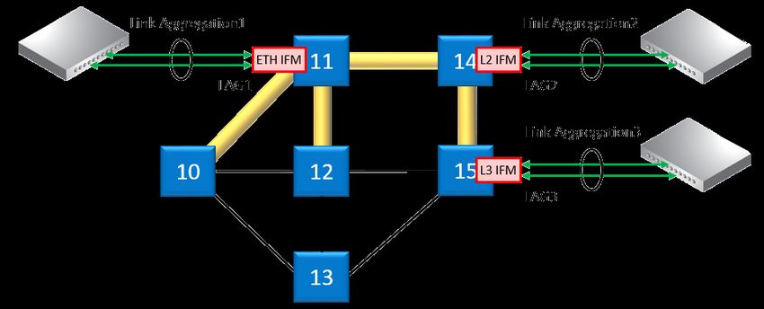
2.2.6 Layer2: Link Aggregation/LAG (=Link Aggregation Group) on CSM310-A
Link Aggregation is the bundling (=aggregation) of multiple physical Ethernet links between a
source and destination side into one combined logical Ethernet link. A LAG is a combination
of multiple Ethernet LAN ports within one logical port group, maximum 8 ports per LAG and 8
LAGs per node. The Link Aggregation is the communication between two LAGs. E.g. one LAG
in one Dragon PTN node and the second LAG in a third party switch/application. For 1G ports,
all the ports of the source and destination LAG must be in autonegotiation. On the Dragon
PTN side, ports with the same speed and linked to the same switch ASIC (CSM, L2 or L3) can
be added to the same LAG. Each bullet shows the possible LAG ports per switch ASIC:
CSM: all Ethernet IFM ports (4-GC-LW, …) of the same speed in the same node;
L2: all 6-GE-L IFM ports;
L3: all 9-L3A-L / 9-L3EA-L IFM ports of the same speed;
NOTE: Example: Ports in different nodes can not be added to the same LAG because they
are linked to different switch ASICs. CSM (4-GC-LW, …), L2 and L3 ports in a same
node can not be added to the same LAG because they are linked to different switch
ASICs.
NOTE: LAG on WAN ports and L2/L3 back end ports is not supported.
Central Switching Module PTN-CSM310-A/PTN-CSM540-A 17
Release 03 05/2020The resulting combined logical link:
has at least the bandwidth of one individual link (1 Gbps bandwidth for a 1G port, 10 Gbps
for a 10G port), but can have more bandwidth if both conditions below are met:
multiple streams from different MAC addresses are streamed over the LAG;
the LAG algorithm loadshares these streams over different links within the LAG;
offers loadsharing based on the source and destination MAC addresses;
offers redundancy in case one of the individual links should fail.
LAG is configured in HiProvision. See Ref. [2Eth] in Table 2 for more configuration information
in HiProvision.
Figure 7 Link Aggregation and LAGs
2.2.7 Self-test
When switching on the supply voltage, the node goes through a self-test, before switching
itself into the network. During this test, the main function blocks are tested e.g. processor,
memories etc.…
2.2.8 Alarming
a. Hardware Device Alarms
The CSM supervises all the hardware in the node and generates the necessary device alarms
when something goes wrong in the node. These alarms are collected by HiProvision. It can be
configured in HiProvision via the Device Settings to output one or more of these alarms to the
digital output contacts (=DO) on the NSM in the node, see also Ref. [2Mgt], [3], [3b] in Table 2.
b. SNMP Traps (future)
Every module in a Dragon PTN node, either NSM, CSM or IFM has a MIB onboard. Every
parameter in each MIB can be configured for alarming. The CSM will monitor all the MIBs in
its node. If a parameter value changes somewhere in the node, the CSM will send out an
(SNMP) trap via the management or DCN channel on the network. HiProvision decides
whether the captured (SNMP) trap results in an alarm or not. All the alarms will be visualized
by HiProvision.
E.g. the user can configure the minimum and maximum value of a temperature parameter on
an IFM. If the temperature exceeds the allowed configured temperature range, HiProvision
will show a temperature alarm for this module on that specific node.
18 Central Switching Module PTN-CSM310-A/PTN-CSM540-A
Release 03 05/20202.2.9 Health Monitor
If you have problems with a specific node, a service in a node, responsiveness of a node,
possible traffic loss is a node, it is always a good idea to verifiy the Health Monitor in
HiProvision (See also Ref. [2Net] in Table 2). This monitor shows more info on the CSM(s)
usage in a node:
CPU usage;
Memory usage;
Disk (=Flash, SD memory card) usage.
2.2.10 Hardware Edition
The hardware edition of the CSM has been factory set and can not be changed! It can be read
out via HiProvision, see Ref. [2Mgt] in Table 2.
2.3 Onboard Interfaces
Micro SD Card Hardware Heat Sink
Interface Edition
Lock
Unlock
Extractor Hidden Reset
handle Button
Figure 8 CSM310-A: Side View
Central Switching Module PTN-CSM310-A/PTN-CSM540-A 19
Release 03 05/2020Heat Sink
Heat Sink
Heat Sink
Management Hidden Reset
Connector Display Button
Figure 9 CSM540-A: Top View
Bottom Side:
Micro SD Card Interface
Figure 10 CSM540-A: Bottom View (Including Micro SD Card)
2.3.1 Heat Sink
A heat sink is required for the natural cooling of the CSM module. A heat sink can reach a high
temperature during operation.
CAUTION: Do not touch the heat sink when the CSM is in operation, or when removing
the CSM from the node. It can be extremely hot. Risk of getting burned!
20 Central Switching Module PTN-CSM310-A/PTN-CSM540-A
Release 03 05/20202.3.2 Straps
No user relevant straps.
2.3.3 DIP Switches
The CSM has no user relevant DIP switches.
2.3.4 CSM Replacement / Micro SD Memory Card
The SD card location can be found in the pictures in §2.3.
The SD card has two purposes:
Allow the easy and fast replacement of a broken CSM in the live network without further
HiProvision interaction. The SD card on the broken CSM always holds the latest node
configuration downloaded via HiProvision.
Offer a container for ‘network database’ backups. When a backup of the database to this
node has been initiated in HiProvision via ‘network backups’, HiProvision will store this
database on this SD card. See also Ref. [2Mgt] in Table 2.
CAUTION:
The SD card from a broken CSM can be reused in the new replacing CSM, provided that
both CSMs have the same firmware version and are used in the same node.
This SD card interface has an SD card plugged in by default. Every time HiProvision loads a new
or updated configuration into the node, this SD card will be updated. As a result, this SD card
always holds the latest node configuration.
Follow the steps below to replace a broken CSM with a new CSM:
Remove the SD card from the new CSM by pushing down and releasing the SD card;
In case of CSM redundancy: If the active CSM has to be replaced, switch over first to make
this CSM the standby CSM;
Remove the broken CSM (=hot-swappable) from the powered node;
Remove the SD card from the broken CSM and insert it into the new CSM;
Plug in the new CSM into the node. The node will reboot with the new CSM, which already
has the correct node configuration from the SD card. A new load of the node via
HiProvision will not be necessary.
Micro SD
Memory Card
Micro SD
Memory Card
Interface
Figure 11 Micro SD Memory Card Interface
Central Switching Module PTN-CSM310-A/PTN-CSM540-A 21
Release 03 05/2020NOTE: This SD card is neither required nor essential for the CSM to operate, but it makes a
possible CSM replacement in the future a lot easier and faster.
NOTE: If the reset button has been pushed at least for seven seconds (see §2.1.3), the latest
configuration on the SD card will be replaced with the factory default settings.
NOTE: A new SD Card can be ordered via order number: V30812-A6073-C3.
2.4 CSM Redundancy
2.4.1 General
Prerequisite: both CSMs must have the same firmware version.
All the Dragon PTN node types, except for the Dragon PTN aggregation node PTN1104, can be
equipped with redundant CSM modules.
CSM Redundancy means that two CSMs are installed in the node. One CSM will be the active
one while the other CSM will be the redundant one. Both CSMs will contain the complete
configuration data of all connections that are configured in that node.
CSM Redundancy provides a higher availability of the services through a node if one CSM
should fail. If one fails, the redundant hot-standby CSM will take over automatically to keep
the node and all its services alive (with a minimal service interrupt).
In normal operation one CSM actively controls the backplane and IFMs, whereas the other
CSM is in standby mode. Both CSMs have a dedicated heartbeat mechanism to control which
CSM is active and which CSM is in standby mode.
2.4.2 Redundancy States
A CSM can be in three different redundancy states: ACT (=Active), STB (=Standby) or PAS
(=Passive). The current state of each CSM can be viewed on the CSM display (see §2.1.4) or on
the LEDs of the NSM.
CAUTION: At installation time, if the spare LED (for CSM310-A) or the ACT LED (for
CSM540-A) on both redundant CSMs are lit together, it means that both CSMs are active
at the same time. This is not allowed! Make sure that both CSMs are plugged in properly.
2.4.3 CSM Switchover
An automatic switchover from the active CSM (=ACT) to the standby CSM (=STB) occurs when:
The active CSM gets broken;
The active CSM is pulled out from the node. It is strongly advised not to pull out the active
CSM intentionally! When a CSM has to be pulled out, make sure it is in standby/passive
mode first via switching-over.
A manual switchover from the active CSM (=ACT) to the standby CSM (=STB) can be done via:
The hidden CSM1/2 switchover button on the NSM module has been pushed for
approximately 4 seconds until the other CSM becomes active, indicated by the LEDs on the
NSM;
The hidden reset button on the active CSM has been pushed (see also §2.1.3);
HiProvision, see Ref. [2Net] in Table 2;
22 Central Switching Module PTN-CSM310-A/PTN-CSM540-A
Release 03 05/2020NOTE: With CSM redundancy, a switchover is only possible when both CSMs have the same
firmware version and one CSM is 'active' and the other CSM is 'standby'.
When a switchover occurs, the connections or services going through that node will be
interrupted shortly.
CAUTION: In case of CSM redundancy, never pull out or reset the active CSM. If you want
to pull out or reset the active CSM (e.g. CSM1), switchover first via HiProvision or the
CSM1/2 button on the NSM. As a result, the intended CSM becomes standby and can be
pulled out or reset.
2.4.4 Revertive/Non-revertive Behavior
CSM Redundancy is non-revertive: once a switchover of the CSM has occurred, the new active
CSM stays active until a manual switchover or switchover caused by an error occurs. No
automatic switchback to the original CSM will occur when this one returns back up and
running after an error.
2.4.5 HiProvision - CSM Connection
CAUTION: When using CSM Redundancy, it is advised that HiProvision is connected to
both CSMs (=each CSM having its own management cable) whenever possible, either
directly or via a router/switch. If only one cable is available, make sure that HiProvision is
connected to the active CSM when performing load actions. If the cable is connected to
the standby CSM, it is possible in HiProvision to make the standby CSM the active one
and vice versa.
For more connection scenarios, see §2.1.5b
2.4.6 Reset Button - Factory Default - Reboot Node
See §2.1.3.
2.4.7 Micro SD Card
The Micro SD Card of the redundant CSM will automatically get the configuration of the active
CSM, see also §2.3.4.
2.4.8 In Service Upgrade/In Service Revert (Redundant CSMs Only)
The ‘In Service Upgrade’ procedure is an enhanced way to upgrade redundant CSMs to a
higher firmware version. It takes less downtime than the normal upgrade procedure for
redundant CSMs.
In service upgrade: downtime is only a few seconds. As a result, running services in that
node will only go out of service for a few seconds, actually it is only the switchover time
from the standby → active CSM;
Normal upgrade: downtime is a few minutes;
Prerequisites:
both CSMs have the same active firmware version;
both CSMs have the same backup firmware version;
Central Switching Module PTN-CSM310-A/PTN-CSM540-A 23
Release 03 05/2020both CSMs must be in synchronization. It means that one CSM must be in the Active state,
and the other one in the Standby state.
How to perform such an upgrade procedure has been described in Ref. [2Mgt] in Table 2.
NOTE: ‘In Service Revert’ (Redundant CSMs only) is a procedure is for falling back to a
previous firmware version and is similar to ‘In Service Upgrade’, see also Ref. [2Mgt]
in Table 2.
2.5 Add a New Node to a Live Network
See Ref.[1] in Table 2.
3. MODULE SPECIFICATIONS
3.1 General Specifications
For general specifications like temperature, humidity, EMI ... see Ref.[4] in Table 2.
3.2 Other Specificiations
Table 10 Other Specifications
Description Value
CSM310-A
Weight 1.1 kg / 2.4 lb
MTBF 71 years at 25°C/77°F
Power Consumption 27W (measured at 25°C/77°F, with data transport)
Module Size width: 60.6 mm / 2.39 inches
height: 126 mm / 4.96 inches
depth: 195 mm / 7.68 inches
HiProvision Connection Via a twisted pair RJ45 connector for 10/100 Mbps BASE-T Ethernet interface
CSM540-A
Weight 1.53 kg / 3.36 lb
MTBF 54.3 years at 25°C/77°F
Power Consumption 50W (measured at 25°C/77°F, without data transport)
Module Size width: 372.5 mm / 14.66 inches
height: 43 mm / 1.69 inches
depth: 202 mm / 7.95 inches
HiProvision Connection Via a twisted pair RJ45 connector for 10/100 Mbps BASE-T Ethernet interface
3.3 Ordering Information
PTN-CSM310-A: 942 230-001
PTN-CSM540-A: 942 230-002
4. ABBREVIATIONS
ASIC Application-Specific Integrated Circuit
BFD Bidirectional Forwarding Detection
CE Conformité Européenne
24 Central Switching Module PTN-CSM310-A/PTN-CSM540-A
Release 03 05/2020CSM Central Switching Module DCN Data Communication Network EC Electromagnetic Compatibility EMI Electromagnetic Interference ERP Ethernet Ring Protection FLT Fault I²C I-Squared-C / Inter Integrated Circuit IEC International Electrotechnical Commission IEEE Institute of Electrical and Electronics Engineers IETF Internet Engineering Task Force IFM InterFace Module ITU International Telecommunication Union LAG Link Aggregation Group LED Light Emitting Diode LVD Low Voltage Directive MIB Management Information Base MPLS-TP Multiprotocol Label Switching – Transport Profile MTBF Mean Time Between Failures NSM Node Support Module OAM Operations, Administration and Maintenance PF Power Failure PI Power Input PRC Primary Reference Clock PSU Power Supply Unit PTN Packet Transport Network PTP Precision Time Protocol SD Secure Digital SHDSL Symmetrical High Bitrate Digital Subscriber Line SNMP Simple Network Management Protocol SSM Sync Status Message SyncE Synchronous Ethernet WAN Wide Area Network WEEE Waste of Electrical and Electronic Equipment Central Switching Module PTN-CSM310-A/PTN-CSM540-A 25 Release 03 05/2020
You can also read