Toward a Generic Human Machine Interface for Assistive Robots: the AMOR project
←
→
Page content transcription
If your browser does not render page correctly, please read the page content below
Proceedings of the 2005 IEEE                                                                                                          WeP01-30
9th International Conference on Rehabilitation Robotics
June 28 - July 1, 2005, Chicago, IL, USA

     Toward a Generic Human Machine Interface for Assistive Robots: the
                            AMOR project
                          Mahmoud Ghorbel, Mossaab Haariz, Bernard Grandjean and Mounir Mokhtari

       Abstract— This paper describes the development of generic                global objective residing on the integration of the MANUS
    Human-Machine Interface (HMI) to control the manus assistive                in the living environment of peoples with disabilities.
    robot. The personalization of the HMI, according to each end                   Actually, we try to achieve this objective in a more
    user, is crucial for the usability of any assistive technology.
    The control of complex devices, such as robot having many                   valorizing way by considering the MANUS as a controlled
    degrees of freedom (DOF), with a limited number of DOF                      object within the intelligent environment composed of sev-
    at the level of the user, implies an appropriate design of                  eral heterogenous objects and appliances. That implies a
    the HMI to facilitate the interaction. Our research activities              strong design of the HMI to facilitate the interaction with a
    focus mainly at this level, which means not only providing                  limited number of DOF at the level of the user. The challenge
    several functionalities of the controlled system, but also on the
    presentation of those functionalities to the user. The challenge            is to hide the complexity of the controlled system to the user
    is to hide the complexity of any controlled system to the                   while giving a generic solution of the HMI to support not
    user, and particularly, when these users are having severe                  only MANUS but also all controlled objects.
    disabilities. Preliminay results are also presented. This work is              The rest of the paper is structured as follows: in section
    funded by a European program, through the AMOR project,                     2 and 3, we describe the general software architecture pro-
    and by national support, through the Smart Home project.
    A demonstration of the running prototype will be presented                  posed to control different appliances and objects integrating
    during the conference.                                                      MANUS, and the HMI functionalities and its different mod-
                                                                                ules. Section 4 highlights the integration of the new module,
                          I. INTRODUCTION                                       called Display Manager, and its contribution to facilitate the
                                                                                interaction with the software. We present also our solution
       The MANUS tele-manipulator is a robot mounted on                         for implementation in / out the COMMANUS computer box.
    an electric wheelchair. Its objective is to favour the inde-                Hence, in section 5 we describe our experimentation platform
    pendence of severally handicapped people who have lost                      we are using in a clinical condition in order to validate and
    their upper and lower limbs mobility, by increasing the                     evaluate our concept. Finally, we summarizes and conclude
    potential activity and by compensating the prehension motor                 the paper.
    incapabilities.
       MANUS is a robot with six degrees of freedom, with                                  II. SOFTWARE ARCHITECTURE
    a gripper in the extremity of the arm which permits the                        Our concept considers the robotic device as an object
    capturing of objects (payload of 1,5 kg) in all directions,                 of the assistive environment, which is composed of several
    and a display. All are controlled by a 4x4 buttons keypad or                assistive devices such as electrical wheelchair, environmental
    by a joystick with the latest prototype version and soon, a                 control system and so on. This concept is based on our
    mouse or a touch screen. The 4x4 keypad gives the user the                  philosophy of separation of these main parts[3]:
    possibility of handling MANUS, and the display unit gives                      1) User Interface layer (UI Layer): manage user interface
    the current state of the MANUS.                                             events according to any input device (keypad, joystick,
       Although the MANUS has a specific software                               voice recognition) selected and configured with the ECS
    architecture[1] and its specific input device already                       (Environment Configuration System) software according to
    mentioned, we had contributed to the research activity                      each end user.
    aiming to enhance this architecture toward a high level                        2) Human-Machine Interaction layer (HMI Layer): This
    controller for the MANUS robot through the COMMANUS                         layer supervises the whole system: it converts user events
    project[2]. Indeed, COMMANUS software architecture was                      into actions according to selected output devices (MANUS,
    integrated all MANUS modes and some extra modes such                        TV, VCR), transmit the information to the different mod-
    as Point-to-point and record modes. This MANUS software                     ules, manage multimodal aspects, manage errors situations,
    improvement phase was aiming at having a modular and                        manage the synchronization of modules, etc.
    open software architecture in order to make easier its                         3) Physical Control Layer (PC Layer): deals with the
    integration, maintenance and evolution. This fits with our                  specific characteristics of any output device and according to
                                                                                its communication protocol (CAN, infra red, radio protocol).
       Mahmoud Ghorbel, Mossaab Haariz and Mounir Mokhtari are with Hand-          The implementation of this concept is illustrated by the
    icom lab, Institut National des Telecommunications, 9 Rue Charles Fourier   figure 1 which shows that the user interface layer is repre-
    91000 Evry, Paris, France. mahmoud.ghorbel@int-evry.fr
       Bernard Grandjean is with INSERM-U483, University Pierre & Marie         sented by the Graphical User Interface (GUI) composed with
    Curie, Paris, France.                                                       several actionmaps. A suitable input device (keypad, joystick,

0-7803-9003-2/05/$20.00 ©2005 IEEE                                          168
suitable representing icons.
The COM module represents the low level controller
having the role of an intermediator between the HMI layer
and the PC layer. It is about an open communication platform
which ensures networking interconnection between HMI su-
pervisor and different environmental devices[4]. The problem
of services and devices discovery is solved using UPnP
technology.
In next chapter, we describe HMI functionalities as well
as the ECS software.
III. THE HUMAN MACHINE INTERFACE (HMI)
Based on the software architecture presented in
ICORR’2003 in South Korea, we have developed a new
software architecture which considers the MANUS robot as
an object of the living environment, at the same level as
an electrical wheelchair or household equipments[3]. This
consideration increases the complexity of the functionalities
of the HMI supervisor. In fact, the diversity of products
brings a wide range of networking protocols necessary to
manage the whole smart environment (CAN, radio, infrared,
Ethernet, PLC: Power Lines Communications, ...).
A. Functionalities
The HMI supervisor is a configurable software layer
considered primarily as the main part of the system and
Fig. 1. Software architecture which allows the connection and interaction between user
and his environment, by the management of all the events:
users events, systems events, order’s external events. The
etc) is selected according to user desires and capabilities in HMI manages the actions of the user and the events which
order to control the interface as comfortable as possible (that come from the system. In parallel, it must consult the
deals with user profile[9]). The GUI can also be configured configurations of the interfaces of entry and effectors to be
according to his desires using the ECS software having a rich able to update or modify the environment. The infrastructure
graphical library. This GUI configuration provides an XML of the HMI implements the following considerations:
output file which is analyzed by HMI supervisor. The HMI 1) Modularity: that allows identifying clearly the various
represents the main core of the the architecture and plays parts, aiming to be able taking again and modifying some ob-
the role of adaptation and coordination between modules. It jects during the design process. The modularity is ensured by
includes the following modules: the separation of the data, the treatments and the presentation.
• Control Module (CM): responsible of the interaction The figure 1 shows different modules in HMI. We can notice
with COM module allowing the exchange of infor- that the data are represented by objects XML, the treatments
mation between different HMI modules and the COM are carried out by the treatment module, whereas, display
module (i.e. request for devices actions list, send com- is ensured by objects inheriting from graphic model and
mands...). including specific characteristics of the type of the interface
• Processing Module (PM): creates different XML objects to be presented.
representing devices and possible actions, makes corre- 2) Extensibility: HMI can be compared to a components
spondence between graphic and XML objects allowing library which implementation is easily ensured by con-
translation of detected user events (as click) to the sidering the previous point. Add/remove of some services
suitable actions and sends commands to the CM. or functionalities implies add/remove of some component
• Dynamic Scan (DS): responsible of environment modi- without modifying the totality of the system.
fication awareness (new device) allowing the update of 3) Communication: This point represents an overriding
the system to take into account new devices in the GUI and primordial aspect bearing in mind that the running of
or to delate removed ones through DM. some objects depends on some intermediary results.
• Display Module (DM): create GUI basing on graphic The role of HMI layer is to allow ordering the various
object previously created by the PM, detect user events devices present in the house. This will generate in some
and sends them to the PM kinds, the sending of an order, or a series of orders, that the
• Graphic Object (GO): every actionmap is represented COM module must realize. An easy solution can solve the
with graphic object containing different actions and problem. It consists to take the name of the action requested
169and to compare it with all actions which can exist. The list of In addition to traditional modes (Cartesian, point-to-point,
actions will be recorded in a table and will be available to the relative ), we have to add a new mode of command using
COM module. Nevertheless, the number of the devices to be video streaming. In this mode the output of a camera fixed
controlled increases progressively, an update of the actions on the gripper, is analyzed to detect the object selected by the
table became necessary, that causes the increase of its size user. After that, the movement of the arm will be relative to
and, thus, the increase of the heaviness of the comparison this object. A video feed-back is displayed on the screen to
task on the level of the COM module. The adapted solution to allow the user being aware about the state of manipulation if
avoid this problem is to create a standard format of the order. he uses the assistive mode, or to have just more information
So, an order contains three fields: header (which contain about his environment, especially for user with very limited
the name of destination device, as MANUS), type (contain movement.
type of order, simple or complex), and finally action (contain Figure 2 presents the interactions between different mod-
action to do by the device). This allows the COM module, ules participating in the assistive control mode. The HMI
with a simple processing of the order, to localize destination is the main core of the MANUS robot controller. The
device and send it the action to do. kinematics module process the actions according to different
mode (point-to-point...) by making simplified points. The
B. Configuration tools: ECS Controller Level Layer (LLC) controls joint tracks.
The situation is that each end user, with his deficiencies In fact, the event of button click in the user interface is
and his individual needs, is considered as a particular case transmitted to the HMI, which associate this event to an
that requires a typical configuration of any assistive system. activity. In the case of changing to the assistive control mode,
Selecting the most adapted input device is the first step the following orders are transmitted to different modules:
and the objective is to allow the adaptation of available • Display manager module: the new disposition of button
functionality’s according to his needs. For this purpose we with the new layout specifying the region where the
have developed a software configuration tools, called ECS video will be displayed.
(Environment Configuration System), which allows a non • Feature Extraction module: a command is transmitted
expert to configure easily any selected input device with to start frame grabbing[6].
the help of different menus containing activities associated Frames extracted from the cameras are transmitted to the
to action commands of any system including the MANUS display module via a shared memory. The aim is to transform
robot. The idea is to describe equipment (TV, Robot, PC), this module into a feature extraction process to assist the
input device (Joystick, Keypad, Mouse), technologies (PLC, user with automated gestures. After extracting the texture
Bluetooth, IP Protocol) using XML and generate automati- of the object to track, assistive commands are transmitted
cally all available functionalities which could be displayed directly to the kinematics, thus, we preserve reel time con-
in an interactive graphical user interface. According to his strain. This part, developed by our partner in the AMOR
needs, and to the selected input devices, the supervisor offers
the mean to associate graphically the selected actions to the
input device events (buttons, joystick movements).
It generates an XML object as standard output which will
be easily downloaded by various ways in our control system.
Supervisor allows in one hand to read XML specification
to create the starting display mode, and to assume the
connection link with physical layers in order to recuperate
changes through dynamic discover[5].
IV. TOWARD AN EMBEDDED DISPLAY MANAGER
The main objective of this module is to provide a convivial
interface to the user. Furthermore, separating display from
HMI and implementing it in a separate module, makes the
display independent from the screen (PDA, Telephone or
other devices). This module will adapt the display infor-
mation to the kind of the screen. In this section, we focus
mainly on the control of the MANUS robot and added video
MANUS controller modules. Fig. 2. The Display Manager Concept
A. Display Manager project; TNO/TPD, is not described in this paper. We will
The Display Manager functionalities start by loading the focus mainly on the Display Manager including the video
initial configuration of the first action map with buttons streaming. To develop this module we have investigate
disposition and display it considering the characteristic of same windows system like X11 server (X Window System,
the screen. Version 11). But these systems require lot of memory or
170such resources are crucial for embedded system. So it was (for example the command MANUS GO RIGHT from the
necessary to use a dedicated windows manager for embedded HMI hay level is translated to low level command by the
system. For this task, we have targeted two solutions based CommandRequest eCMD MOVE with parameter specifying
on existing standards: the movement in all DOF), but if we want to communicate
1) QT/EMBEDDED[7]: This system is completely com- with other actuators the HMI will address the command to
patible along with the entire Qt class library. It represents the appropriate actuator such as an electrical wheelchair.
a good implementation of a Windows-look-and-feel applica- To validate this concept we use a development kit based
tions framework that can be supported by an embedded de- on PDA architecture, we use also windows CE as Operating
vice with a framebuffer quite easily. However, Qt/Embedded System and C++ as Language. Our concept can be repre-
could not be run on any non-Qt framework. Consequently, sented by the figure 3:
we had to made some changes in the software architecture.
This increased the complexity of the system.
2) The MICROWINDOWS operating environment[8]:
This framework is faster than Qt/Embedded, and it is well
suited for general applications development. This environ-
ment is well suited for platforms where a large third-
party contribution is desirable, such as devices made for
the general public, or where different technologies must be
applied together without restricting the language or APIs
used for development. However After investigating, we have
found that Microwindow is not event oriented, it manages
only (x,y) pointing of the cursor.
We have implemented the Display Manager using QT en-
vironment on a standard PC architecture as testing platform
to deal with feasibility. The video streaming was provided
by a standard USB camera. The software control of the
MANUS, based on RT-Linux, was done through a CAN
communication protocol with the Arm. We still need some
Fig. 3. Embedded Modular Controller
investigation to an embedded system mounted on an elec-
trical wheelchair. Below we describe the existing platform We have add a class to the Kinematics layer (Remote
which should be demonstrated during the conference. Device Detection) which manage the start up process of the
B. Embedded Modular Controller software Commands changed between modules are:
A perspective solution we are working on is to make 1) Method invocation between HMI and Display Manager
the human-machine interface generic and fully compliant the announce event to the HMI.
with traditional existing controller commercialized by Exact 2) TCP/IP channels to communicate configuration file at
Dynamics. Our solution consists on separating the HMI the beginning and later on Kinematics command from
from the kinematics. This will allow exporting the HMI the remote HMI.
on different controller (PC, PDA...). The configuration tool 3) Kinematics command received from the Local HMI.
(ECS) provides actually a default XML file that contains 4) LLC Command via TCP channel from Kinematics
the configuration for the embedded version witch target a Layer.
standard screen. Our idea is to extend the ECS tool to 5) Electric command to motors via CAN BUS
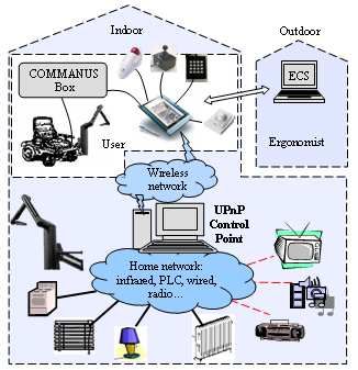
generate configuration files for other devices like (smart V. EXPERIMENTATION PLATFORM
phone, PDA, EASY RIDER). These configuration files will
In order to make experimentation and evaluate this con-
be stored on the control box. We start by launching the
cept, we have established our platform based on a smart
kinematics module and it wills wait for socket connection
home model. The deployment of this platform is real envi-
from a remote device. Two scenarios are considered:
ronment involving users is planned through the rehabilitation
1) If there is connection the Kinematics will detect the hospital of Garches located near Paris in regard to the
nature of the device and it will upload the specific con- national project ”smart homes and handicap”.
figuration file. Every device will implement a version
of the HMI witch fit with its futures. A. Platform description
2) there is no connection the default HMI and the Display The platform, illustrated in the figure 3, consists of several
Manger based on QT existing on the box will be software and hardware elements. The first actor in the
launched based on the default XML file. platform is the user having his Manus robot mounted on
In both scenarios the HMI will communicate with the kine- his wheelchair. The tablet PC provided to the user with
matics via TCP/IP channel containing a Hmi-Kinematics- a suitable input device, contains software modules pre-
Command that will be processed by the Kinematics Layer installed like graphical interface and the HMI supervisor.
171• The evaluation of the GUI ergonomy showed that size
of buttons and their representation on the screen were
highly considered by the users. Adaptation with input
devices workspace(ex. Joystick)and motor capabilities
of users was necessary.
• The Tablet PC used (10 inches size) was considered
invading of wheelchair user space. Mobile terminals,
such as PDA or smart phones presented to users,
were considered more suitable to be installed on the
wheelchair.
CONCLUSION
In this paper, we have tried to present our vision on
the Human Machine Interaction in controlling a complex
system, such as MANUS robot. The aim is to consider a
generic HMI which hide the complexity of the robot and
allow controlling any device in the living environment of
people having severe disabilities. We developed an HMI
which could be implemented on an embedded computer box
including a display manager compliant for video streaming.
Fig. 4. Smart Home demonstration platform
This paper describes the concept, the developed prototype,
and the main requirements obtained with the participation of
end-users. A demonstration of the system should be provided
This terminal allows user to control his robot (ethernet during the conference. In future work we are planing mainly
connection) as well as his environment through wireless to improve the HMI with Easy Rider system (wheelchair
connection (WiFi) to a home supervisor PC. This supervisor control)developed by HMC company and implement it on a
contains UPnP control point with suitable software (UPnP PDA.
gateway to other protocols) allowing interaction with X10 ACKNOWLEDGEMENTS
PLC (Power Line Communication) modem and RC5 infrared
This research work was funded by the European Com-
transmitter. Each electrical appliance is connected to an
mission through the AMOR project under contract G1ST-
X10 receiver and brown goods integrate RC5 protocols.
CT-2002-50261. The authors would like to thank all AMOR
Finally, configuring and addressing steps should be done
partners: TNO-TPD, Exact Dynamics, HMC, Lund univer-
during system initialization. So the system can discover
sity, Antwerpen University, AFM, and Permobil.
different devices and services existing in the environment,
and controlled temporarily with a proposed dynamic user R EFERENCES
interface. This user interface could be personalized according [1] B. Driessen, T. T. Kate, H. Evers: ” MANUS Control Architecture”.
to user requirements with the help of developed configuration 7th ICORR proceeding, ISBN 1 58603 171 6 (IOS Press), France
tool ECS. 2001, p 215.
[2] B. Abdulrazak, B. Grandjean, M. Mokhtari: ” Toward a new high level
controller for MANUS robot: The COMMANUS project”. 7th ICORR
B. User needs investigation proceedings, ISBN 1 58603 171 6 (IOS Press), France 2001, p 221.
[3] M. Mokhtari, B. Abdulrazak, M.A. Fki, R. Rodriguez, B. Grand-
We have performed several evaluations of the system jean: ”Integration of Rehabilitation Robotics in the Context of Smart
within the rehabilitation hospital of Garches. 13 Users having Homes: Application to Assistive Robotics”. 8th ICORR proceedings,
ISBN 89 88366 09 3, Korea 2003, p 5.
spinal cord injuries and muscular dystrophies have partipated [4] M. Ghorbel, M. T. Segarra, J. Kerdreux, R. Keryell, A. Thepaut,
in the experimentations. Detailed results on the usability of M. Mokhtari: ”Networking and Communication in Smart Home for
Manus robot have been published in [10]. The evaluation of People with Disabilities”. 9th ICCHP proceedings, ISBN 3 540 22334
7, France 2004, p 937.
the generic HMI consisted on using a tablet PC to control [5] B. Abdulrazak, M. Mokhtari, M. A. Fki: ”Generic user interface
both the robot and the environment. The main recommenda- for people with disabilities: Application to smart home concept”. 1st
tion highlighted were: ICOST proceedings, ISBN 1 58603 380 8, France 2003, p 45.
[6] B. J. Driessen, T. K. ten Kate, and J. A. van Woerden. ”User Centered
• The presence of a visual feedback contributes mainly to Design of Rehabilitation Robotics”. 8th ICORR proceedings, ISBN 89
simplify the learning phase. This implies the reduction 88366 09 3, Korea 2003, p 262.
[7] Qt/Embedded Overview, http://www.trolltech.com/products/embedded/
of the learning time up to 30 minutes for the majority [8] MicroWindows web site, http://www.microwindows.org/
of the users. [9] R. Kadouche, B. Abdulrazak, M. Mokhtari: ”Toward an evaluation
• The use of the ECS tool to configure GUI remained methodology for computer accessibility”. 2st ICOST proceedings,
ISBN 1 58603 457 X, Singapore 2004, p 49
very appreciable by users. We observed that it was [10] B. Abdulrazak: ”Interaction homme-machine dans le cas d’un handi-
essential to have 2 to 5 iteration to obtain an acceptable cap moteur” PhD.University of Evry-Val dEssonne, INT, Mai 2004
personalized version.
172You can also read