Please Use This Owners Manual - Propel Trampolines
←
→
Page content transcription
If your browser does not render page correctly, please read the page content below
Please
Use
This Owners
Manual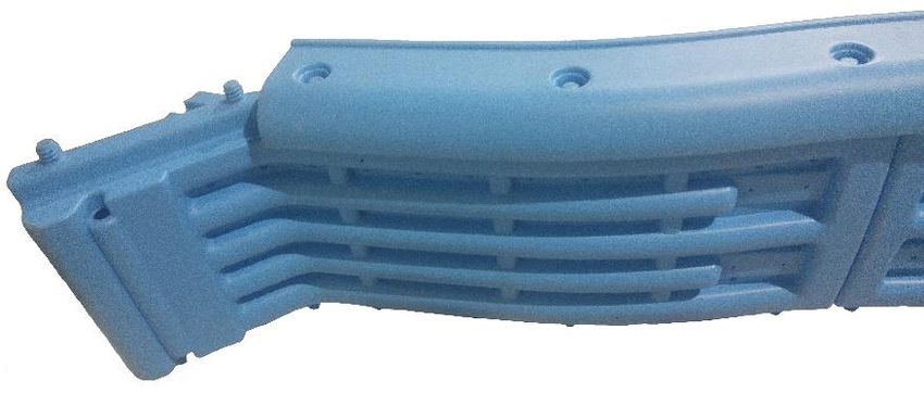
9 Station Swing Set
                     User Manual
                                      For model: P9-SS-19

           Assembly, Installation, Care, Maintenance,
                     and User Instructions

                                          WARNING
  READ THESE MATERIALS PRIOR TO ASSEMBLING AND
              USING THIS SWING SET.
Failure to assemble and use this swing set as specified in this manual will automatically void the
warranty.

Page 2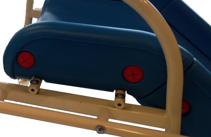
Do Not return this product to the store. Instead, please visit our
        website at www.PropelTrampolines.com where you will find our
        current contact information. Our friendly customer service staff
        can help you with any problems or questions that may arise during
        the assembly, installation, use, maintenance, or obtainment of
        replacement parts for your Swing Set.

 This conforms to ASTM F1148, Consumer Safety Performance Specification
                    for Home Playground Equipment.

                                      WARNING
Read all assembly, care, maintenance, and user instructions in
this manual prior to assembling and using this Swing Set.

Please save this manual for future reference and check our
website for the latest manual revisions.

                                  LIABILITY DISCLAIMER:
While every attempt is made to embody the highest degree of protection in all equipment, we cannot
guarantee freedom from injury. The user assumes all risk of injury due to use, assembly, or transportation.
All merchandise is sold on this condition. No representative of the company can waive or change disclaimer
condition.

                                                    Warning
This Swing Set is designed to be used safely by up to 9 children with a maximum weight per station of 105 pounds each.
The combined weight should not exceed 945 pounds on the swing set.

                                                                                                                  Page 3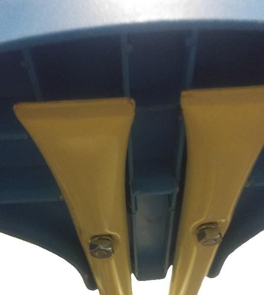
BEFORE YOU BEGIN
  Thank you for purchasing a Propel Swing Set.

  This swing set comes equipped with warnings and instructions for its proper assembly, care,
  maintenance, and use. This information must be read by all supervisors and users before any
  person is allowed to use it.

  Follow all warning pictures included in this manual. If you have any questions regarding these
  warnings, please contact us.

  After reading this manual, if you have further questions, or if you would like to contact us,
  please visit our website at www.PropelTrampolines.com.

                                         Warning
  1. Place the equipment on level ground, not less than 6 ft. (1.8 m) from any structure or
     obstruction such as a fence, garage, house, overhanging branches, laundry lines, or
     electrical wires. Swings should be further away from structures to the front and rear of
     the swings – a distance equal to twice the height of the top bar from which the swing is
     suspended by.
  2. DO NOT install home playground equipment over concrete, asphalt, packed earth,
     grass, carpet, or any other hard surface. A fall onto a hard surface can result in serious
     injury or death to the equipment user.
  3. This product must be anchored to the ground with the included anchors (see anchor
     installation section for anchoring the swing set). The anchoring devices must be placed
     below the level of the playing surface to prevent from tripping or injury resulting from a
     fall. Anchor installation instructions can be found on page 23 of this manual.
  4. Children must not use this equipment until it is properly installed.
  5. One week after assembly, check equipment for loose or missing bolts. Tighten and
     replace if needed.
  6. Fall Height: 72”

  User should read and understand rules. Supervisor should be sure that these rules are
  always properly followed:

Page 4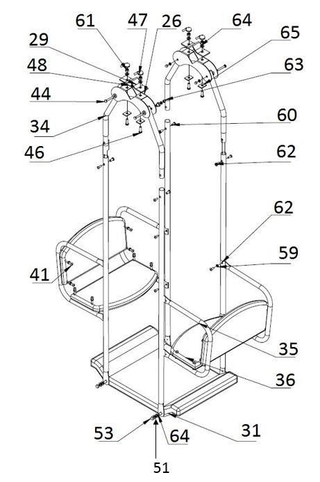
Operating Instructions
                                                    Warning
1.    Observing the following statements and warnings reduces the likelihood of serious or fatal injury.
2.    Adult supervision is recommended for children of all ages, at all times while the swing set is being used.
3.    Do not allow children to walk close to, in front of, behind, or between moving items.
4.    Do not allow children to twist swing chains or ropes or loop them over the top support bar since this may reduce
      the strength of the chain or rope.
5.    Teach others to avoid swinging empty seats or items. They may strike others or come back and strike them.
6.    Teach all users to sit in the center of the swings with their full weight on the seats. Do not stand on the seats. Do
      not allow children to lean to the side of the equipment while using it or collide with other playmates.
7.    Do not use the equipment in a manner other than intended.
8.    Do not get off of equipment while it is in motion.
9.    Do not allow children to jump from moving play items.
10.   Users should be dressed appropriately. Users wearing inappropriate items such as but not limited to, loose fitting
      clothing, hood and neck drawstrings, scarves, cord-connected items, cape, and ponchos should not be allowed to
      play on the equipment. These items can cause death by strangulation.
11.   Do not climb on the equipment when it is wet.
12.   Check the openings between rollers and sliding surfaces of roller slides for foreign materials that could be
      potentially hazardous to users.
13.   Make sure that all suspended climbing ropes, chains, or cables are secured at both ends.
14.   Make sure that all suspended climbing ropes, chains, or cables cannot be looped back on itself.
15.   Do not allow others to attach items to playground equipment that are not specifically designed for use with the
      equipment, such as, but not limited to, jump ropes, clotheslines, pet leashes, cables and chains as they may cause a
      strangulation hazard.
16.   Users need to remove their bike or other sports helmet before playing on the playground equipment.
17.   Users need to be dressed in well-fitting and full foot enclosing footwear. Examples of inappropriate footwear are
      clogs, flip flops, and sandals.
18.   WARNING: Lawn swings are designed for use by children two years of age and older. The use by children under
      the age of two can result in entrapment between the seat and back rest because the child’s body may pass through
      the opening, causing entrapment of the child’s head. Such entrapment may result in strangulation. NEVER place
      children in a rearward facing position or with legs between the seat and backrest.

         IMPORTANT: UNITED STATES CONSUMER PRODUCT SAFETY
       COMMISSION’S (USCPSC) Outdoor Home Playground Safety Guidelines:

 One of the most important things you can do to reduce the likelihood of serious head injuries
is to install shock-absorbing protective surfacing under and around your play equipment. The
protective surfacing should be applied to a depth that is suitable for the equipment height in
accordance with ASTM Specification F1292. There are different types of surfacing to choose
from; whichever product you select, follow these guidelines:

     1. Loose-Fill Materials:
           a. Maintain a minimum depth of 9 inches of loose-fill materials such as wood
              mulch/chips, engineered wood fiber (EWF), or shredded/recycled rubber mulch
              for equipment up to 8 feet high; and 9 inches of sand or pea gravel for equipment
              up to 5 feet high. NOTE: An initial fill level of 12 inches will compress to about
              a 9-inch depth of surfacing over time. The surfacing will also compact, displace,
                                                                                                                     Page 5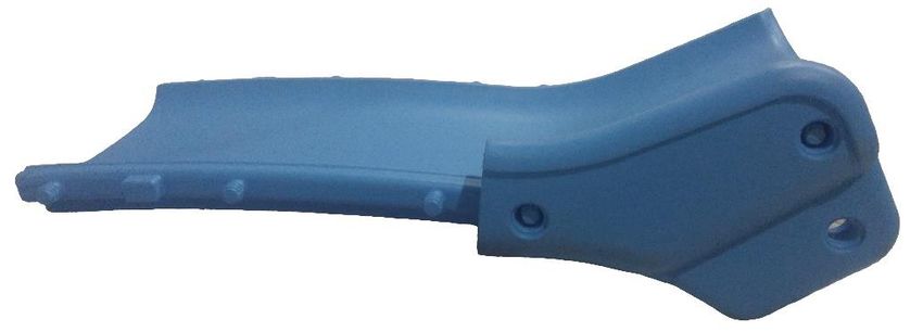
and settle, and should be periodically refilled to maintain at least a 9-inch depth.
            b. Use a minimum of 6 inches of protective surfacing for play equipment less than
                4 feet in height. If maintained properly, this should be adequate. (At depths less
                than 6 inches, the protective material is too easily displaced or compacted.)
                NOTE: Do not install home playground equipment over concrete, asphalt, or
                any other hard surface. A fall onto a hard surface can result in serious injury to
                the equipment user. Grass and dirt are not considered protective surfacing
                because wear and environmental factors can reduce their shock absorbing
                effectiveness. Carpeting and thin mats are generally not adequate protective
                surfacing. Ground level equipment – such as a sandbox, activity wall, playhouse
                or other equipment that has no elevated play surface – does not need any
                protective surfacing.
            c. Use containment, such as digging out around the perimeter and/or lining the
                perimeter with landscape edging. Don’t forget to account for water drainage.
            d. Check and maintain the depth of the loose-fill surfacing material. To maintain
                the right amount of loose-fill materials, mark the correct level on play equipment
                support posts. That way you can easily see when to replenish and/or redistribute
                the surfacing.
            e. Do not install loose fill surfacing over hard surfaces such as concrete or asphalt.
    2. Poured-In-Place Surfaces or Pre-Manufactured Rubber Tiles:
       You may be interested in using surfacing other than loose-fill materials – like rubber
       tiles or poured-in-place surfaces.
            a. Installations of these surfaces generally require a professional and are not “do-it-
                yourself” projects.
            b. Review surface specifications before purchasing this type of surfacing. Ask the
                installer/manufacturer for a report showing that the product has been tested to
                the following safety standard: ASTM F1292 Standard Specification for Impact
                Attenuation of Surfacing Materials within the Use Zone of Playground
                Equipment. This report should show the specific height for which the surface is
                intended to protect against serious head injury. This height should be equal to or
                greater than the fall height – vertical distance between a designated play surface
                (elevated surface for standing, sitting, or climbing) and the protective surfacing
                below – of your play equipment.
            c. Check the protective surfacing frequently for wear.
    3. Placement - Proper placement and maintenance of protective surfacing is essential. Be
       sure to:
            a. Extend surfacing at least 6 feet from the equipment in all directions.
            b. For to-fro swings, extend protective surfacing in front of and behind the swing
                to a distance equal to twice the height of the top bar from which the swing is
                suspended.
            c. For tire swings, extend surfacing in a circle whose radius is equal to the height
                of the suspending chain or rope, plus 6 feet in all directions.
Page 6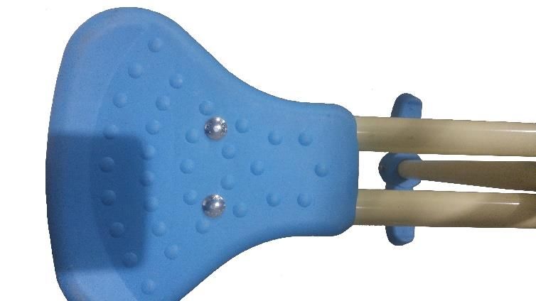
Parts List

(1) Angled Leg Bracket                (2) Straight Leg Bracket
            x2                                     x1             (3) Top Frame Braces                   (4) 5/16” Glider Wash

                                                                                    Welded A Frame in the Center
              Has two square crimps

                      (5) Top Rail A                                                      (6) Top Rail B
                                                                                  Has one square crimp

                      (7) Top Rail C                                                      (8) Top Rail D

            (9) Lower Frame Leg Pole x6                                         (10) Upper Frame Leg x6

            (11) Leg Brace for Ladder x1                                            (12) Leg Brace x2

                      (13) Slide                                                     (14) Slide Rails

(15) Slide Bottom A                   (16) Slide Bottom B        (17) Slide Side Rail A                  (18) Slide Side Rail B

                                                                                                                            Page 7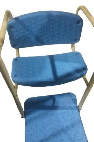
B                              A

                                                                                 (20) A & B Teeter Totter Brace x2 each

                         (19) Ladder Brace x2                                               (21) Ladder Leg x4

                                                                                                        (25) ¼” x 2” Bolt for Slide Rail
     (22) Slide Support Bar           (23) Slide Bottom Rail Bar           (24) Ladder Step x2                        x2

 (26) Carriage & Teeter Totter                                                                          (29) Carriage &Teeter Totter
           Bracket x3               (27) Teeter Totter Footrest x2     (28) Teeter Totter Seat x2              Top Bracket x3

  (30) Carriage and Glider Rod       (31) Carriage and Glider Base
               x4                                  x2                      (32) Gymnast Bars                  (33) Swing Seat x2

                          B
       B

           A

       (34) A& B Carriage
       Seat Brace x4 each             (35) Carriage Arm Rest x4           (36) Carriage Seat x4             (37) Slide Plugs x22 Total

      (38) 5/16” x 2-3/4” Bolt           (39) 5/16” Glider Washer         (40) ¼” x 1-2/5”” Bolt            (41 )1/4” X1-1/5”Bolt

 (42) ¼” x 2-3/4” Bolt              (43) ¼” x 1-3/8” Carriage Bolt   (44) 1/4” x 1-3/4” Carriage Bolt             (45) J Bolt

      (46) 5/16” x 1” Bolt                      (47) Cap             (48) 5/16” X 3/5” Brace spacers        (49) Ladder Spacer x2

Page 8
(50) ¼” x ¾” Screw x4                  (51)5/16” Nut       (52) 5/16” X ½” Brace spacers            (53) 5/16” Cap Nut

(54) 2/5” Curved Washer           (55) 5/16”Curved Washer          (56) Anchor x6                  (57) 5/16” X 2-1/6 bolt

  (58) 5/16” Thru Nut                 (59) 1/4” Washer           (60) 1/4” Thru Nut                 (61) 5/16” Nylon Nut

(62) 1/4” X 11/16” Bolt                                                                          (65) Teeter Totter Bracket
           X8                          (63) ¼” Cap Nut           (64) 5/16” Washer                       Washer x6

                (66) Swing Seat Chains                                              (67) Glider Chains

                         (68) Teeter Totter Seat Supports                                    (69) 1/4” Nylon Nut

                                                                                                                      Page 9
ASSEMBLY INSTRUCTIONS
                IMPORTANT ASSEMBLY INFORMATION

  • The following tools are included: Phillips Screwdriver, regular screwdriver, 4mm Allen
    wrench, 5mm Allen wrench and 10mm / 13mm wrench.
  • Assembly requires two adults.
  • Wear gloves to protect your hands from pinch points during assembly.
  • You should wear clothing and gloves during assembly which will not be damaged or
    stained by any residue.

                                Frame Assembly
    Read and understand all assembly instructions before beginning the assembly process.
  Step 1 – Select Top Rail A (5) and insert the narrow end into Top Rail B (6). The Rectangle
  slots need to be down on all top rail sections.

Page 10
Step 2 – Repeat Step 1 by inserting Top Rail B (6) into Top Rail C (7) and then Top Rail D
(8) into Top Rail C (7).
Step 3 – Bolt together the Top Rails with the Top Frame Braces (3) (these braces are
installed on the underside of the Top Rails). First align the Top Frame Brace (3) with the
holes on the Top rail. Ensure all holes on top rail line up with holes on Frame Brace. Put a
5/16” Washer (64) on Bolt (38). Slide through holes from bottom side, put on a Cap (47)
then a 5/16” Nylon Nut (61). Loosely tighten. Do this on all three sections where the rails
insert into each other. Note: Bolts should enter braces and rails from the underside with
the nut and cap being placed on the top side of the rails. Repeat until all three braces are
complete with 4 bolts in each brace.
Page 11Step 4 – Attach the Upper Frame Legs (Cream Color) (10) to Top Rail A (5), Top Rail B
(6), and Top Rail D (8). Slide an Upper Frame Leg (10) into the welded A-frame on Top
Rail. Align the holes. Insert 5/16” x 2-3/4” Bolt (38) with a 5/16” washer (32) and then
feed it through the leg bracket and leg. On the opposite side attach Cap (47) then a 5/16”
Nylon Nut (61). Loosely tighten the hardware. Once all the hardware is in place tighten up
the bolts. Repeat this step on the remaining Upper Frame Legs.
10
Step 5 – Attach the Lower Frame Leg Poles (Green Color) (9) to the Upper Frame Legs
(10). Slide the Lower Frame Leg Poles (9) into the Upper Frame Leg (10). Align the
holes.
10
9
Page 12Step 6 - Attach Leg Braces (11) to the Upper Frame Legs (10). Start on the side with the
Top Rail A (has the two square crimps). Insert 5/16” x 2-3/4” Bolt (38) with a 5/16”
washer (64) into the flat part with hole on Leg Brace (11). Indents on Leg Brace (11) face
inward. Install this leg brace to the leg (Make sure the leg brace is on the outer part of the
frame). Loosely tighten the leg brace, lower frame leg, and upper frame leg together by
bolting it on with a Cap (47) then a 5/16” Nylon Nut (61) (see images below). Repeat this
step to attach a Leg Brace (12) on the next two sets of legs. The center leg brace can be
placed on either side of the Frame Legs.
11
12
12
Page 13Accessory Assembly Read and understand all assembly instructions before beginning the assembly process. Step 1 – Attaching the swings. Note: The Chains have triangle eye bolts on each end. The longer eye bolt goes through the top rail. First insert one end of the Swing Seat Chain (66) into the swing seat (33). Fasten it to the seat by using 5/16” Washer (64), 5/16” Cap (47), and Nylon Nut (61). Repeat this for the other side and additional swing seat. Then attach the other end into the rectangle punched slots on Top Rails A, B, and C. Use a 5/16” Curved Washer (55), cap (47), and a 5/16” Nylon Nut (61) to attach it to the top rails. Repeat step for second swing. Page 14
Step 2 – Attach the Gymnast Bars (32) to Top Rail C (following the directions in Step 1
of attaching the swings to the top rails). Note: The Chains have triangle eye bolts on each
end. The longer eye bolt goes through the top rail. If the handles are not attached to the
short chains use the 5/16” Thru Nut (58) to attach them to the chain. Fasten 5/16” Nut (51)
to triangle eye bolt. Place gymnast handle over triangle eye bolt. Fasten with 5/16” Thru
Nut (58). Tighten 5/16” Thru Nut (58) 1st, then Tighten 5/16” Nut (51).

                                                                                      Page 15
Step 3 – Attach the Glider Chains (67) to the Glider Base (31) by first inserting 2 Carriage
and Glider Rods (30) into the glider base holes. Then put the one end of the Y from the
chain on the rod and the other end on the same side on the other rod. Fasten them onto the
rods by using two 5/16” Glider Washer (39) on each side of chain, and 5/16” Cap Nut (53).
Repeat this on the other side of the glider. Attach it to the rectangle punched slots on Top
Rails C and D (see step 1 on how to attach it to the top rail). Note: One Glider base is to be
used with Glider and one Glider base is to be used for the carriage.
One Washer to be placed
inside chain and one on
outside.
Page 16Step 4 – Attaching and Assembling the Carriage. First attach the Carriage & Teeter
Totter Brackets (26) to the two square crimps on Top Rail A. Do this by putting Carriage
& Teeter Totter Bracket (26) on the bottom side of the frame, then fasten it on with the
Carriage & Teeter Totter Top Bracket (29), 5/16” x 1” Bolt (46), Teeter Totter Bracket
Washer (65), Cap (47), and 5/16” Nylon Nut(61). (The Bracket Washer goes on the
underneath side of the assembly).
Page 17Then insert the Carriage and Glider Rods (30) into the Carriage and Glider Base (31) holes. The Carriage and Glider Rods (30) are 46-1/4”. Bolt on the Carriage Seat Brace (34) to the Carriage Base by using a 5/16” Washer (64) on the inner part of the rod, an additional 5/16” Washer (64) on the outer part of the rod, 5/16” Nut (51), and Cap Nut (53). NOTE: Make sure the square notches on each pole are facing inside on the Carriage Seat Braces. Page 18
Join Carriage Seat Brace (part 34 A and 34 B)(34) together by inserting them into each
other, then attaching them with 1/4”x 11/16” Bolt (62) and the 1/4” Thru Nut (60). See
Diagram Below. Note: Pre-drilled holes in long poles need to face inward to complete
carriage A.
Insert 2 Brace Spacers (48) into the top of the Carriage Brace Holes. Slide it into the
Carriage & Teeter Totter Bracket and align the holes. Fasten to the Teeter Totter Bracket
using 1/4” x 1-3/4” Carriage Bolt (44), ¼” Washer (59), and 1/4” Cap Nut (63).
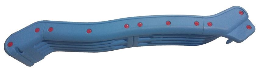
Page 19Attach the Carriage Arm Rests (35) to the Carriage Seat Braces. Align the Carriage Arm
Rests with the squared notch on the inside of the Carriage Seat Braces B. Fasten them to the
Braces with 1/4”x 11/16” Bolt (62) and 1/4” Washer (59). The hole in the post is threaded.
Finally attach the Carriage Seat & Back Rest (36) to the Carriage Arm Rests. Use 1/4”
x 1-1/5” Bolt (41) and 1/4” Washer (59) to bolt them to the arm rests. Holes for bolts are
threaded. Note: Ensure pre-threaded holes are positioned to accept seat and seat back rest
hardware.
Position pre-
threaded holes
as shown
Page 20Step 5 – Attaching and Assembling the Teeter Totter. First attach the Carriage & Teeter
Totter Bracket (26) to the single square crimp on Top Rail D. Do this by putting Carriage
& Teeter Totter Bracket (26) on the bottom side of the frame, then fasten it on with the
Carriage & Teeter Totter Top Bracket (29), 5/16” x 1” Bolt (46), Teeter Totter Bracket
Washer (65), the 5/16” Nylon Nut (61) and Cap (47). (The Bracket Washer goes on the
underside of Carriage and Teeter Totter Bracket).
Insert Teeter Totter Brace Spacer B with Plastic Caps (20) into the Teeter Totter Bracket
and align the holes. Fasten to the Teeter Totter Bracket using 1/4” x 1-3/4” Carriage Bolt
(44), 1/4 ” Washer (59), and 1/4”Cap Nut (63). (The Teeter Totter Brace Spacer with Plastic
Caps (20) comes in two pieces. Attach the top piece to the longer, 48”, bottom piece using
the 1/4” x 11/16” Bolt (62) and the 1/4” Thru Nut(60).
Page 21Insert 2, 5/16” x 1/2" Brace Spacers (52) into each side of the Teeter Totter Brace (20).
Align the brace spacer and Teeter Totter Seat Supports (68) with the holes on the Teeter
Totter Brace (20). Fasten the supports to the brace by inserting J bolt (45) into the support
bar with two holes and then insert the 1/4” Thru Nut (60) through the other side. Loosely
tighten.
Attach the Teeter Totter Seat (28) to each end of the Horizontal Support Bars (68).
Attach them with the 1/4” x 1-3/8” Carriage bolt (43), 1/4" washer(59)” and 1/4” Cap Nut
(63). Note: Loosely tighten until seats are attached.
Page 22Finally attach the Teeter Totter Foot Rest (27) to the bottom of Teeter Totter Brace B
(20). Use (4) each 1/4” x 3/4” Screws (50) to screw them to the braces.
Page 23Step 6 – Assembling the slide. Put the Slide Bottom B (16) on the right side of the bottom
piece.
Slide the upper slide into the groove on the bottom piece, and then put the Slide Rail (14)
on it. Then put the Slide Side Rail A (17) on the very top piece. Attach all the side rails with
the Slide Plugs (37). Screw them on with a screwdriver.
Page 24In the bottom hole on the Slide Bottom insert the Slide Bottom Rail Bar (23) and fasten
to the slide bottom with the Slide Plugs (37).
(Flip the side onto its other side and repeat Step 6)
Page 25Step 6 – Assembling the slide ladder. Take the Ladder Legs (21) and attach the Ladder Steps (24) to them. Attach them with the 1/4”x 1-1/5”” Bolt (41) and 1/4” Cap Nut (63). Page 26
Attach the Ladder Legs (21) to the ladder braces by inserting them into the ladder brace and
then attaching them with 1/4”x 1-2/5”” Bolt (40), 1/4” Curved Washer (54), an additional
curved washer (54), and the 1/4” Cap Nut (63).

                                                                                      Page 27
Attach the ladder to the main frame by lining up the holes on the Ladder Brace with the holes on the Leg Brace for the ladder that is attached to the swing set legs. Insert the 1/4” x 2-3/4” Bolt (42) into the holes on the frame Leg Brace. Then slide the Ladder Spacer (49) onto the bolts. Then put the ladder brace on the bolts. Tighten to the brace using a 1/4” Washer (59) ¼ Nylon Nut (69), and 1/4” Cap Nut (63). Page 28
Finally attach the slide to the ladder. Slide the Slide Support Bar (22) into the two
grooves under the slide. Set the slide and support bars onto the ladder and line up the holes
on each side. Fasten the slide to the ladder using the 1/4” x 2” Bolt for Slide Rail (25), 1/4”
Washer (59), and 1/4” Cap Nut (63) for the Slide Rail. Repeat for both Slide Bars. Note:
When installed properly, the direction and location of slide should be as shown on the User
Manual Cover Page. If slide does not match picture, please remove, rotate, and fasten.

                                                                                         Page 29
Your swing set assembly is complete. Make sure that all
parts are securely attached. Familiarize yourself and all users
of the swing set with all safety precautions. Use the
instructions, care, and maintenance materials in this manual before
using the swing set.
Your swing set is now fully assembled.
Swing Set Anchor Kit
It is highly recommended that you secure your swing set to prevent tipping. Please follow the
instructions below to install the anchoring kit.
Step 1- Insert the Anchor (56) into the hole at the bottom of the leg.
Step 2- Using a rubber mallet, pound each stake at a 45-degree angle into the ground until it is
flush with ground level.
This completes the installation of your Anchor Kit.
Warning: The installation and use of an anchor kit does not guarantee that your swing set will not tip over or be damaged by wind or
other severe weather. Many factors such as soil types influence the effectiveness of this product. Using an anchor kit is not an insurance
policy and will not add additional warranty benefits to your Swing Set. Propel Trampolines and its retailers/affiliates will not be held
responsible for damages to persons or property as a result of the failure of this product.
WARNING LABEL PLACEMENTS
These labels have been attached to the Swing Set. Please verify that none of these labels are missing or
illegible. If so, please contact us and request a free replacement.
Page 30CARE AND MAINTENANCE
CARE
• Do not allow children to walk close to, in front of, behind, or between moving items.
• This Swing Set is designed to be used safely by up to 9 children with a maximum
weight per station of 105 pounds each. The combined weight should not exceed 945
pounds on the swing set.
• Do not allow anyone to twist swing chains or ropes or loop them over the top support
bar since this may reduce the strength of the chain or rope.
• Users should sit in the center of the swings with their full weight on the seats.
• Use equipment only as intended.
• Do not use equipment if you are wearing inappropriate items, such as but not limited
to, loose fitting clothing, hood and neck drawstrings, scarves, cord-connected items,
capes, and ponchos. These items can cause death by strangulation.
• Do not climb on equipment when it is wet.
• Check openings between rollers and sliding surfaces of roller slides for foreign
materials that could be potentially hazardous to users.
• Verify that suspended climbing ropes, chains, or cables are secured at both ends.
• Verify that suspended climbing ropes, chains, or cables cannot be looped back on
itself.
• Have users remove their bike helmets or other sports helmets before playing on the
swing set.
• Make sure users are dressed in well-fitting and full foot enclosing footwear. Examples
of inappropriate footwear are clogs, flip flops, and sandals.
Page 31MAINTENANCE
Your swing set was manufactured using the highest quality materials. It was crafted to provide
you and your family with years of enjoyment and exercise. Proper maintenance and care will
help to prolong the life of your swing set. Proper maintenance will also reduce the possibility
of injury. The following guidelines should always be followed:
1. At the beginning of each play season:
a. Tighten all hardware
b. Check all protective coverings on bolts, pipes, edges, and corners. Replace if they
are loose, cracked, or missing.
c. Check all moving parts including swing seats, ropes, cables, and chains for wear,
rust, or other deterioration. Replace as needed.
d. Check metal parts for rust. If found, sand and repaint using a nonlead-based paint
meeting the requirements of 16 CFR 1303.
e. Reinstall any plastic parts, such as swing seats or any other items that were
removed for the cold season.
f. Rake and check depth of loose fill protective surfacing materials to prevent
compaction and to maintain appropriate depth. Replace as necessary.
2. Twice a month during play season:
a. Tighten all hardware
b. Check all protective coverings on bolts, pipes, edges, and corners. Replace if they
are loose, cracked, or missing.
c. Rake and check depth of loose fill protective surfacing materials to prevent
compaction and to maintain appropriate depth. Replace as necessary.
3. Once a month during play season:
a. Check all moving parts including swing seats, ropes, cables, and chains for wear,
rust, or other deterioration. Replace as needed.
4. At the end of each play season or when temperature drops below 32º F (0º Celsius)
a. Remove plastic swing seats and rings and take indoors or do not use.
b. Rake and check depth of loose fill protective surfacing materials to prevent
compaction and to maintain appropriate depth. Replace as necessary.
5. Owners shall be responsible for maintaining the legibility of the warning labels.
6. When it is time to dispose of the swing set, please disassemble the swing set completely
Page 32and dispose of it in such a way that no unreasonable hazards will exist at the time the
swing set is discarded.
DISASSEMBLY
To disassemble (take apart) the swing set, follow the swing set assembly steps in reverse order.
Use gloves to protect your hands from pinch points while taking the swing set apart.
REPLACEMENT PARTS
To order replacement parts please visit our website at www.PropelTrampolines.com. Before
visiting the website be sure you know the model number of your swing set. If you need
assistance ordering parts or have other questions about your swing set, please call the customer
service number listed in the Information section of our website.
Page 33For more information or to order any of these accessories,
please visit our website at www.PropelTrampolines.com.
MY SWING SET INFORMATION
In the event you need to contact customer service, such as to ask questions, order replacement
parts, or file a warranty claim, you will be asked to provide some basic information about your
swing set. By writing this information in the spaces below and keeping this Manual in an
accessible location, you can help expedite this process.
Staple or otherwise affix dated sales receipt here.
If it is necessary to file a warranty claim, you will be asked to provide a copy for proof of date
of purchase.
__ __
The following information can be found printed on the end of the box in which your swing
set came.
Model or Item number: _
_________________________________________
MF Code:____ __________________________________________________________
Manufacturing Facility:_____________________________________________
Page 34LIMITED WARRANTY
PROPEL warrants its swing set products to be free from defects in material and workmanship under
normal use and service conditions. The powder coated steel frame are warranted for one (1) year
from the date of purchase. All other parts are warranted for ninety (90) days from the date of
purchase.
All warranty coverage extends only to the original retail purchaser from the original date of
purchase. Our obligation under this warranty is limited to replacing or repairing the product at our
discretion. All products for which a warranty claim is made must be received by us at one of our
authorized service centers. Freight must be prepaid and accompanied by proof of purchase. All
returns must be pre-authorized. This Warranty does not extend to any product, or damage to a
product that is caused by or attributable to freight damage, abuse, misuse, improper or abnormal
usage, act of God, storm damage, installation or use of accessories, repairs not performed by our
authorized service center, and to products used for commercial or rental purposes. No other warranty
expressed or implied beyond that specifically set forth above is authorized.
Propel Trampolines is not responsible or liable for indirect, special, or consequential damages arising
out of, or in connection with the use or performance of this product. Propel is not responsible for
other damages with respect to any economic loss, loss of property, loss of revenue or profits, loss of
enjoyment or use, cost of removal or installation, and any other consequential damages. In the
United States of America some states do not allow the exclusion or limitation of incidental or
consequential damages. Accordingly, the above limitation may not apply to you.
The warranty extended hereunder is in lieu of all other warranties, and any implied warranty of
merchantability or fitness for a particular purpose is limited in its scope and duration to the terms
set forth herein. In the United States of America some states do not allow limitations on how long
an implied warranty lasts. Accordingly, the above limitation may not apply to you.
This warranty gives you specific legal rights. You may also have other rights which vary from state
to state in the United States of America.
Page 35Warranty Registration
Don’t forget to register your Swing Set by
visiting www.PropelTrampolines.com/warranty.
Registering your Swing Set entitles you
to receive all warranty benefits.
You may also register your Swing Set
by mailing a copy of your sales receipt
along with your name, address, phone number
and the model number of your trampoline to:
Propel Trampolines
Warranty Department
41 East 400 North #324
Logan, UT 84321
www.propeltrampolines.com
V1.8 - © 2020 Propel Trampolines
Page 36You can also read