NETALLY VOIP READINESS TUTORIAL - NETALLY VERSION 7 PREFACE
←
→
Page content transcription
If your browser does not render page correctly, please read the page content below
NetAlly®
          VoIP Readiness Tutorial

                NetAlly Version 7
Preface
Tutorial Overview
The purpose of this tutorial is to introduce the concept of Distributed Active Network
Testing using NetAlly VoIP Assessment and Troubleshooting. After completion of this
tutorial, you will be able to install and operate NetAlly, launch VoIP Evaluation Sessions,
generate reports based on collected data, examine Web-based analysis reports and
peek into setting-up and running troubleshooting tests.
How to Use this Tutorial
Each chapter in the tutorial deals with a specific subject. It introduces you to key
concepts of NetAlly and familiarizes you with its various capabilities, features and
advantages. The tutorial walks you through the various available VoIP evaluation
procedures as well as the required steps for performing the procedure.
To get the maximum out of this tutorial, it is recommended to read the chapters in the
order in which they are listed:
Chapter 1 – describes the operation of NetAlly, its use and users.
Chapter 2 – describes NetAlly installation.
Chapter 3 – walks you through the setup required for a VoIP Evaluation Session.
Chapter 4 – describes the Network Configuration and its report.
Chapter 5 – describes the Readiness Assessment and its report.
Chapter 6 – describes the Performance Certification and its report.
Chapter 7 – describes the Web-based Analysis Reports and workflow.
Chapter 8 – provides a review of setting up and running network analysis and
troubleshooting tests.
Tutorial Aids
Detailed descriptions of installation, setup and operation of NetAlly are available in the
following guides provided in PDF
NetAlly Getting Started Guide
NetAlly User Guide
Page 2 of 43Introduction
Objectives
The objectives of this chapter are as follows:
Provide a concise description of NetAlly VoIP Readiness and its operation.
Describe when to use NetAlly
Describe the advantages of NetAlly
Describe the typical users of NetAlly
NetAlly Capabilities
NetAlly is a software-based distributed active system that is capable of the following:
Network Configuration - checks aspects of the network’s configuration such as network
connectivity and the quality of service settings for VoIP traffic.
Readiness evaluation – NetAlly determines quickly and automatically the network
readiness for VoIP. It is capable of reaching remote locations and performing end-to-end
testing in a short time and without the need for dispatching technicians or test tools to
remote locations.
Troubleshooting – NetAlly identifies application and service related readiness issues
across the entire IP network. The problem identification and analysis are accomplished
from a single location.
Application effects – NetAlly generates application traffic to test how applications affect
voice traffic and vice versa.
Note
This tutorial focuses on readiness evaluation. It will guide you on how to assess the
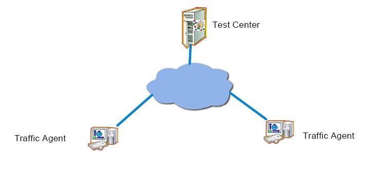
readiness of your network for VoIP.How Does NetAlly Operate?
NetAlly communicates through its Test Center with any number of software-based
Traffic Agents. The Traffic Agents are located throughout the Local Area Network (LAN)
or Wide Area Network (WAN). A three-phase evaluation procedure allows you to assess
and confirm the network’s readiness for the added VoIP traffic, prior to actual
deployment by simulating emulating VoIP and application traffic.
The evaluation procedure includes the following phases:
Network Configuration - checks aspects of the network's configuration and consists of
three different tests – Connectivity, VoIP traffic precedence (QoS policy) and Route
quality and utilization measurements.
Readiness Assessment – uses tests that simulate a varying range of calls. The tests
identify the maximal number of calls that test point pairs can handle.
Performance Certification – uses a fixed number of calls to run an intensive evaluation
on the network over a longer period of time.
Exhaustive and customizable reports documenting each phase of the evaluation are
available.
NetAlly VoIP Components
The NetAlly system comprises the following components:
Test Center (TC) – the NetAlly control center that runs on a dedicated
workstation. Among other functions, the Test Center schedules VoIP tests for
execution, operates Traffic Agents, stores data within an internal database, and
manages topology data.
Traffic Agents (TA) – software agents installed on dedicated or on end user
machines. The Traffic Agents send each other a wide variety of network traffic
packets. The packets are analyzed and used for generating network performance
reports. These packets simulate the output of different VoIP codecs. Packet
parameters (for example, QoS level) may be customized to the needs of
particular tests. The primary measurements used in the analysis of VoIP traffic
are MOS (Mean Opinion Score), delay, loss and jitter. When testing VoIP
readiness, Traffic Agents are attached to the network at locations that represent
user location. VoIP tests carried out by these Traffic Agents provide performance
measurements from the end user perspective.
Page 4 of 43 NetAlly User Interface (GUI) – client software designed for testing the readiness
of a network prior to deploying VoIP traffic, monitoring your network and
performing network analysis and troubleshooting. At the beginning of the VoIP
readiness evaluation process, the user sets the participating test point pairs and
determines the call parameters.
NetRegard Agents – unique Web browser-based Traffic Agents. The agents can
be used for VoIP testing and troubleshooting on end-user machines.
What Are the Advantages of Using NetAlly?
NetAlly distributed traffic generation has the following advantages:
Capacity estimation – Generating tests with variable number of calls allows you
to estimate the maximal number of calls the network can carry.
VoIP readiness – using software agents, you can evaluate the network readiness
for VoIP before deployment of any VoIP equipment.
Ease of use – VoIP readiness evaluation is easy and quick. A few mouse clicks are
all you need for running an evaluation phase and for obtaining reliable results.
Drill-down troubleshooting capabilities – On-demand generation of actual
traffic allows you to rapidly identify network performance degradation between
two end-points.
Test control and repetition – The flexibility in setting VoIP test parameters
provides you with complete control over what is being tested and how.
Furthermore, the accuracy and applicability of test results can be verified by
repeating identical tests at different times.
True objectivity – Since identical VoIP tests can be applied to different portions
of the network, valid comparisons can be made between them. This results in
objective determination of capacity and when troubleshooting, of the sources or
potential sources of degraded network performance.
Who Should Use NetAlly?
VoIP equipment resellers who are responsible for deploying and verifying VoIP
readiness of networks.
Network managers or integrators who are responsible for evaluating whether
the network is ready for the VoIP application.
Network engineers who are responsible for network troubleshooting or VoIP
deployment projects.
Page 5 of 43When to Use NetAlly?
Use NetAlly in the following cases:
Pre- and post-deployment testing for VoIP applications.
Troubleshooting performance anomalies in networks and networked
applications.
Problem solving of network performance anomalies as they affect the end user
and the user’s voice quality experience.
Summary
NetAlly can measure the network’s VoIP performance and pinpoint where
improvements are required. The assessment can be tailored to each network through an
easy to use and friendly interface. The results of the evaluation are presented in
detailed reports that provide comprehensive information regarding the readiness of the
network for VoIP traffic.
Proceed to the following chapter to learn how to set up the network for the session
described in this tutorial.
Chapter 2
Page 6 of 43NetAlly Installation Objectives The objectives of this chapter are as follows: Install NetAlly Test Center. Install NetAlly Traffic Agents. Install the User Interface. Setting up the Network for the Tutorial Session This tutorial requires a simple setup, as shown below. The setup includes three Windows-based machines connected to a network. One machine is a Test Center and the other two are Traffic Agents. The User Interface, which can be installed remotely on the NetAlly operator’s desktop, will be installed on the same machine as the Test Center for this tutorial. For the tutorial session, the Traffic Agent will be installed on the same machine as the Test Center. The Traffic Agent can also be installed as a remote client on other Windows 2003 Server or XP and Vista machines.
System Requirements

The following table lists the system requirements for the Test Center, Traffic Agent and
User Interface:

                            Operating System                   RAM         Disk Space
                      Windows XP, SP 1 and later;             512 MB          2 GB
                      Server 2003;
                      Windows Vista.
                      Intel Pentium IV, 1.4GHz
Test Center
                      processor and greater or Pentium
                      M processor.
                      Intel Xeon, 1GHz processor and
                      greater.
                      Windows XP, SP 1 and later;             256 MB         200 MB
                      Server 2003; Windows Vista.
Traffic Agent         Intel Pentium III 800 MHz
                      processor and greater or Pentium
                      M processor.
                      Windows XP, SP 1 and greater;           256 MB         200 MB
                      Windows Server 2003; Windows
                      Vista.
                      Intel Pentium IV, 1.4GHz
User Interface        processor and greater or Pentium
                      M processor.
                      Display: color palette of at least
                      16-bit colors.
                      Resolution: 1024 x 768.
                      Windows XP, SP 1 and greater;           512 MB         300 MB
                      Windows Vista.
                      Intel Pentium IV 1.4GHz
NetAlly Proxy
                      processor and greater.
                      Intel Xeon, 1 GHz processor and
                      greater
                      Microsoft Internet Explorer,
NetRegard
                      version 6.0 and later.
Agent
                      Mozilla, version 1.4 and later.

                                                                               Page 8 of 43
Pre-Installation
Prior to installing, verify the following:
That you have the NetAlly version 7 software or CD, the NetAlly product keys and
the NetAlly license file.
That you have administrator privileges on the Test Center and Traffic Agent
machines.
That you have the IP address or Host Name of the Test Center. It is required
during Traffic Agent installation.
That there is no firewall between the NetAlly components (applies only to this
setup).
That each machine has only one network interface card (NIC) (applies only to this
setup).
Installing NetAlly Software
1. Do either of the following:
On the Test Center machine, insert the NetAlly CD to automatically run Setup,
Or Run the Setup.exe file located in the root folder to start Setup.
2. Select Install NetAlly Version 7.
3. Select Test Center Installation.
4. Click Begin Installation to run the Installation wizard.
5. Follow the instructions on the screen and do not close any of the windows that
appear during the installation.
Enter the product key number when asked.
When the Test Center is ready, its icon appears in the system tray. Since after
installation it takes a few minutes for the initial setup to be completed, it may take a
few minutes before the Test Center icon appears.
Installing the License File(s)
After the Test Center is installed, all functionality is disabled until the license file is
installed.
To install the license file:
1. Make sure that the Test Center is running.
2. To activate the License Installer, select Start>Programs>Fluke
Networks>NetAlly>Tools>License Installer
3. Browse to the location where you saved the license file (extension *.txt) and
click OK to start its installation.
Page 9 of 43Once the license is installed successfully, the Test Center functionality is updated
according to your license configuration. There is no need to restart the Test Center.
Installing the User Interface
1. Do either of the following:
On the Test Center machine, insert the NetAlly CD to automatically run Setup,
Or
Run the Setup.exe file located in the root folder of the CD to start Setup.
2. Select Install NetAlly Version 7.
3. Select User Interface Installation.
4. Click Begin Installation to run the installation wizard.
Follow the onscreen instructions and do not close any of the windows that
appear during the installation.
Installing Traffic Agents
The following instructions walk you through the installation of the Traffic Agent
software.
Install it on each Traffic Agent machine.
1. Do either of the following:
On the Traffic Agent machine, insert the NetAlly CD to automatically run Setup,
Or
Run the Setup.exe file located in the root folder to start Setup.
2. Select Install NetAlly Version 7.
3. Select Traffic Agent Installation.
4. Click Begin Installation to run the Installation wizard.
5. Follow the onscreen instructions and leave default settings as they are unless
indicated otherwise below. Do not close any of the windows that appear during
the installation.
6. In the listed screens, note the following:
IP Address/Host Name – Enter the Test Center IP address or Host Name.
When the installation is completed, the Traffic Agent icon appears in the system tray.
Invoking the User Interface
1. Select Start>Programs>Fluke Networks> NetAlly>User Interface.
2. In the Login dialog box, enter the following default values in lowercase letters:
Username – admin
Password – admin
Test Center – 127.0.0.1 (Localhost)
Page 10 of 433. Click OK.
4. Verify that both installed Traffic Agents appear in the Traffic Agents area on the
lower part of the NetAlly window, and their status is “Ready”.
Select for VoIP Assessment
Create a new session
Traffic Agents listed
Page 11 of 43Summary
You have successfully completed the installation of the Test Center, Traffic Agents and
User Interface. The system is ready for VoIP readiness evaluation. Proceed to the next
chapter to set up the parameters for the VoIP evaluation.
Page 12 of 43Setting up the Evaluation Session
Objectives
In this chapter you will set up a VoIP Evaluation Session by following these steps:
Define the Session type.
Define a Traffic Agent Pair.
Define a Codec and Codec-specific parameters.
Define call parameters.
Define number of calls.
Define general parameters.
Defining the Session Type
1. Select File>Add>New Session.
2. Enter the name of the new session and select VoIP Traffic in the New Session
dialog box.
Defining a Traffic Agent Pair
The Traffic Agent pair represents the test points between which the evaluation tests are
run. During both the Preliminary and Performance Certification phases, full duplex VoIP
calls are emulated between the delineated pairs (as indicated by the icon between the
left and right Traffic Agent columns).
To define a Traffic Agent Pair:
1. From the listed Traffic Agents, drag a Traffic Agent and drop it into either the left
or right column.
2. Drag another Traffic Agent and drop it into the other column.Note
The codec, codec-specific parameters, call parameters and number of calls are
specific to each Traffic Agent Pair. The General parameters are common to all Traffic
Agent pairs.
Defining the Codec and Codec-Specific Parameters
The tests carried out for each evaluation phase are based on the type of codec selected
for the Traffic Agent pair. The G.711, G.729, G. 729b, G.726 and G.723 codecs are
currently supported. Table 2 lists the specific parameters of the default codec - G.711.
For this tutorial, use the default codec and its default parameter values.
To define a codec for the tutorial:
1. Select the Traffic Agent pair.
2. Verify that the G.711 codec appears in the Codec column. If not, click on the
codec name and select the G.711 codec.
3. In the Traffic Agent Pair Parameters pane, select the Codec Specific Parameters
tab and using Table 2, check that the default Codec Specific Parameters appear.
Page 14 of 43Select traffic agent pair Set traffic agent pair parameters
Table 2: G.711 Codec-Specific Parameters
Parameter Description Default
Value
Frame Packing Time interval at which the digitized VoIP packets are 20 msec
transmitted (in msec) and the resulting payload size
(sampled frames) of the packets.
G.711 Payload Determines the type of analog to digital converter PCMU
Type emulated by the test. To emulate VoIP sessions (64000
according to the method used in the USA, select PCMU; bps)
to emulate VoIP sessions according to the method used
in Europe, select PCMA
Page 15 of 43Parameter Description Default
Value
Use PLC When selected, activates the Packet Loss Concealment Not
(PLC) algorithm which favorably affects the voice quality selected
and resulting MOS calculations.
Silence When selected, activates the silence suppression VAD Not
Suppression (Voice Activity Detection) algorithm for the G.711 codec. selected
Defining Call Parameters
To define call parameters:
Select the Traffic Agent Pair Parameters
Using Table 3, verify that the default parameters appear.
Page 16 of 43Table 3: Call Parameters
Parameter Description Default
Value
Number of Number of points where intermediate measurements 1
Measurements are to be taken during the call.
The default value indicates that no intermediate
measurements are taken.
Base RTP Port The port to be used in the test. According to the base 0
port specified, consecutive even numbered ports will be
used.
If the default port setting is retained, the system
allocates the port automatically.
Jitter Buffer When selected, activates jitter buffer management, Not
which is used by the VoIP receiver to transform the selected
variable delay to a fixed delay by holding the first packet
received for a period of time before playing it out.
Two related parameters, Jitter Buffer Maximum Depth
and the Initial Playout Delay, must also be specified.
Jitter Buffer Maximum Depth: Maximum amount of
voice samples that can be stored in the jitter buffer.
Should be 1.5 or 2 times the value of the Initial Playout
Delay in order to reduce the chances of losing packets
(default = 80 msec).
Initial Playout Delay: The holding time of the first voice
sample received when the jitter buffer is empty, before
starting the transmission of the buffered samples to the
receiving codec.
Too small a value will not eliminate the delay variability
(jitter), while large values will increase the delay (default
= 40 msec).
Quality of The DiffServ or IP TOS-based QoS setting that DiffServ(46)
Service determines the transmission priority of the packets.
Defining Number of Calls
The number of calls indicates the full duplex calls that are emulated between the Traffic
Agent pair during Readiness Assessment and Performance Certification.
Readiness Assessment – assesses the maximum number of calls that can be handled
between the various Traffic Agent pairs with acceptable MOS results. To obtain accurate
and reliable results this evaluation phase is repetitive. Prior to running Readiness
Assessment, provide a range of calls and the application dynamically changes the
number of calls during test execution to arrive at the optimal number.
Page 17 of 43Table 4 describes the number of calls parameters.
Table 4: Number of Calls Parameters
Parameter Description Default
Value
Min Num of Minimum number of simultaneous voice calls to 1
Calls generate on the same connection.
Max Number Maximum number of simultaneous voice calls to 1
of Calls generate on the same connection
Step Number of calls by which to increment the voice calls 1
per period.
Performance Certification - validates the results of Readiness Assessment and,
therefore, emulates a fixed number of calls over a period of time. If the results of the
Readiness Assessment are satisfactory, you can use the recommended number of calls.
Otherwise, you can manually specify the desired number.
To define the number of calls:
Select a pair of Traffic Agents and select the Traffic Agent Pair Parameters
1. Select the Number of Calls tab.
2. For Readiness Assessment, define the range of calls as follows:
Min Number of Calls – 3
Max Number of Calls – 5
Step – 1
Page 18 of 43Save and launch session
Defining General Parameters
General parameters are common to all Traffic Agent pairs and include thresholds for
MOS (Mean Opinion Score), delay, loss and jitter. Table 5 describes the general
parameters.
Call performance is assessed in terms of the low and high MOS threshold values that are
defined. In addition, the thresholds for delay, loss and jitter are used to ascertain the
effect of the values measured for these parameters on the MOS results.
Page 19 of 43To define values of the general parameters:
1. Click
2. Set Conversation Duration to 20 sec, for this tutorial.
3. Using Table 5, verify that the default values appear for the other parameters.
4. In order to perform utilization measurements, the SNMP community strings
must be configured in the Community List in the Route Quality tab.
5. Click to save the session you have defined.
Table 5: General Parameters
Parameter Description Default
Value
Conversation The length in time of the VoIP call generated by the 60 sec
Duration test.
MOS Threshold An alert is provided when the measured average MOS 3.6
is below the threshold value.
Loss Threshold An alert is provided when the measured loss is above 1.0%
the threshold value.
Jitter Threshold An alert is provided when the measured absolute 30 msec
average jitter is above the threshold value.
Delay Threshold An alert is provided when the measured average delay 150 msec
is above the threshold value.
Page 20 of 43CPU Threshold Applicable only when CPU measurement is activated. 80.0%
Defines the acceptable level of CPU usage.
Packet Latency Maximum estimated network delay used for internal 3000 msec
Tolerance test parameters such as calculating the length of the
test, and the timeout parameter.
Single Receiving When selected, the receiving TA receives all calls on the Not
Port same port. selected
The default port that is used can be changed through
the port allocation mechanism.
Measure CPU When selected, measures the CPU and correlates it Not
with the CPU threshold defined. selected
Note
MOS is defined between 5 (good) and 1 (bad). Measured MOS above 3.6 is
considered acceptable for VoIP traffic.
Launching Evaluation Overview
Launching evaluation consists of running either the Readiness Assessment or
Performance Certification.
Usually and for this tutorial, run the Readiness Assessment first and then when it ends
the Performance Certification.
However, in the future, you may wish to run only one of the phases, for example, only
the Performance Certification. You can stop either evaluation phase at any stage of its
operation.
Notes
Session definitions cannot be modified once an evaluation phase is launched.
However, you may use the Save As option to prepare an additional session.
To achieve the most accurate results for your VoIP evaluation, it is
recommended not to use both the Test Center and the Traffic Agents specified
to run other tests while the NetAlly VoIP Evaluation session is running.
Summary
In this chapter, you familiarized yourself with all of the required parameters for
launching an evaluation phase. The following chapter will walk you through running the
Readiness Assessment, generating and understanding the available report.
Chapter 4
Page 21 of 43Network Configuration Detection Objectives The objectives of this chapter are as follows: Run the Network Configuration Detection phase. Generate Network Configuration Detection report. Understand the report. Network Configuration Detection checks aspects of the network’s configuration such as network connectivity and the quality of service settings for VoIP traffic, and presents the results in Network Configuration report. This can be considered as preparatory to the more lengthy Readiness Assessment and Performance Certification phases in the overall scheme of evaluating the network’s readiness for VoIP applications. You can use the information from the tests carried out in this phase to proactively correct general and VoIP-specific network anomalies before initiating the evaluation phases. Running Network Configuration Detection This phase consists of different tests which check the following for each pair of Traffic Agents: Connectivity VoIP traffic precedence (QoS policy) Route quality and utilization measurements To run Network Configuration Detection: 1. Verify that all session definitions are specified. 2. Click and the Launch Evaluation dialog box opens.
3. In the Launch tab, select Network Configuration Detection and check the tests to
      be performed.
   4. In the Schedule tab, set the start time of the session to Now.
   5. Click OK.

Session Test Views

The session tests are displayed by either selecting Readiness and Performance
Certification and then selecting Open session tests or by right-clicking on the session
then selecting Open session tests.
In the Detail view, the result icon is a green checkmark if the results are satisfactory;
otherwise, it is a red cross.

                                                                                 Page 23 of 43
Generating the Network Configuration Detection Report
The Network Configuration Detection report can be generated only after the evaluation
phase is completed. The report is based on a predefined template and can be exported
to MS Word or Adobe Acrobat files.
To generate the Network Configuration Detection report:
1. Select Readiness Assessment and Performance Certification>Generate
Reports>Network Configuration or click the Icon.
The Generate Network Configuration Report dialog box opens.
Page 24 of 432. Enter the filename.
3. Select Export Now.
Understanding the Network Configuration Report
In section 2 of the report, the Connectivity Tests verifies the status of the Traffic Agent
Pairs.
Section 3 of the report contains information on the QoS Policy.
Section 4 contains the results of the Route Quality Test and provides information on:
The route between the Traffic Agents.
The Memory, CPU and Interface Utilization of the routers.
Summary
Once you have learned how to run a Network Configuration test, proceed to the
following chapter and learn how to run the Readiness Assessment, generate a report
and understand it.
Page 25 of 43Readiness Assessment
Objectives
The objectives of this chapter are as follows:
Run the Readiness Assessment phase.
Generate Readiness Assessment report.
Understand the report.
As explained earlier, Readiness Assessment assesses the maximum number of calls that
can be handled between the various Traffic Agent pairs with acceptable MOS results.
Running Readiness Assessment
Readiness Assessment runs tests according to the codec defined for the test point pair.
These tests emulate an increasing number of concurrent VoIP calls during each test
period, using the range of calls provided, until the maximum number is reached or
exceeded. To obtain accurate and reliable results, the evaluation is repetitive. The
results are correlated with the predefined MOS thresholds.
An algorithm then computes the maximal number of calls that can be handled per
Traffic Agent pair with acceptable MOS results, and presents these on demand.
The tests are relatively short and are automatically scheduled and executed.
To run Readiness Assessment:
1. Verify that all session definitions are specified.
2. Click and the Launch Evaluation dialog box opens.3. In the Launch tab, select Readiness Assessment and verify that the number of
iterations is 3 and set Recurrence to Every 30 seconds. To obtain accurate
and reliable results this evaluation phase is repetitive. The more iterations
you run, the more reliable the results are going to be. On the other hand, if
you increase the number of iterations, the duration of the preliminary phase
will also increase.
4. In the Schedule tab, set the start time of the session to Now. There are
situations where you would prefer to schedule your VoIP Evaluation to run
during the night in order to prevent overloading the network during office
hours.
5. Click OK.
Session Test Views
The session tests are displayed by either selecting Readiness and Performance
Certification and then selecting Open session tests or by right-clicking on the session
then selecting Open session tests.
In the Detail view, the result icon is a green checkmark if the results are satisfactory;
otherwise, it is a red cross.
Page 27 of 43Generating the Readiness Assessment Report
The Readiness Assessment report can be generated only after the evaluation phase is
completed. The report is based on a predefined template and can be exported to MS
Word or Adobe Acrobat files.
To generate the Readiness Assessment report:
4. Select Readiness Assessment and Performance Certification>Generate
Reports>Readiness Assessment or click the Icon.
The Generate Readiness Assessment Report dialog box opens.
Page 28 of 435. Enter the filename.
6. Select Export Now.
Understanding the Readiness Assessment Report
In section 2 of the report, the Summary of Results table provides the recommended
number of calls with the corresponding MOS value.
When using the recommended settings for this tutorial and running the test over a LAN,
the test should yield a MOS value of 4.4. If the test yields another result, it most
probably indicates that the connection between your agents is not ready for VoIP. You
can review the next sections in the report to understand what affected the MOS score.
Section 3 of the report contains procedural details.
Section 4 contains the detailed results of the test point pair for the number of calls you
tested:
The first graph shows the MOS value.
The second graph describes the delay, loss and jitter effects on the call quality
(MOS). Each bar represents the relative impact that each measurement had on
the overall MOS value.
Page 29 of 43 The next three graphs provide the average values of the delay, jitter and loss
during the tests.
Summary
Once you have learned how to run a Readiness Assessment, proceed to the following
chapter and learn how to run the Performance Certification, generate a report and
understand it.
Chapter 5
Page 30 of 43Performance Certification
Objectives
The objectives of this chapter are as follows:
Specify the number of calls.
Run the Performance Certification phase.
Generate the Performance Certification report.
Understand the report.
As explained earlier, the Performance Certification validates the results of Readiness
Assessment and, therefore, emulates a fixed number of calls over a period of time.
Running Performance Certification
Performance Certification corroborates the estimates generated during the Readiness
Assessment phase by checking call performance over a long period of time. The time
range makes it possible to assess VoIP performance according to time of day and day of
week under varying network traffic conditions.
Unlike Readiness Assessment, this phase emulates an explicit number of full duplex calls
between each Traffic Agent pair.
The actual number of calls to be emulated can be defined either automatically or
manually. The automatic option uses the number of calls derived from running the
Readiness Assessment and assigns it to the corresponding Traffic Agent pairs.
Alternatively, calls can be assigned manually for each Traffic Agent pair or several Traffic
Agent pairs.
If the results of the Readiness Assessment are satisfactory, use the recommended
number of calls. The Auto Assign Number of Calls option automatically propagates the
number of calls to the corresponding Traffic Agent pairs. Selecting a Traffic Agent pair
and then clicking the Number of Calls tab shows the assigned number under
Performance Certification.
To activate the Auto Assign option click
To run Performance Certification:
1. Verify that the number of VoIP calls to be emulated is defined.
2. Click .
The Launch Evaluation dialog box opens.
Page 31 of 433. In the Launch tab, select Performance Certification and specify 2 hours as the
duration. Set Recurrence to Every 15 minutes.
4. In the Schedule tab, set the start time of the session to Now.
5. Click OK.
Generating Performance Certification Reports
Tip
You can generate a Performance Certification report during the ongoing phase.
In this case, the report will include data collected up to that point.
To generate the Performance Certification reports:
1. Select Readiness Assessment and Performance Certification>Generate
Reports>Performance Assessment or click the Icon.
The Generate Performance Certification Report dialog box opens.
2. Enter the filename.
3. Select Export Now.
Page 32 of 43Understanding the Performance Certification Report
In section 2 of the report, the Summary of Results includes a table with the average
MOS value per test point pair, as well as pie charts depicting the voice quality
distribution per codec over all test point pairs.
Section 3 of the report contains procedural details.
Section 4 of the report contains the aggregated results per tested codec:
The first sub-section shows the average per test point pair of the MOS value,
delay, jitter and loss and their relative effect on the call quality (MOS).
The second sub-section displays the daily average of these measurements and
their relative effect on the call quality (MOS). The average consists of all test
point pairs using this codec.
The third sub-section displays the hourly average for each hour of the day of
these measurements and their relative effect on the call quality (MOS). The
average consists of all test point pairs using this codec.
Section 5 presents detailed results for each of the test point pairs participating in the
Performance Certification phase:
The first sub-section displays the daily average of these measurements and their
relative effect on the call quality (MOS).
The second sub-section displays the hourly average for each hour of the day of
these measurements and their relative effect on the call quality (MOS).
Section 6 documents the setup used for Performance Certification.
Summary
You have completed your first NetAlly VoIP readiness session. You can set up additional
sessions using other available codecs with additional Traffic Agents as your test point
pairs. To further familiarize yourself with NetAlly VoIP, run several evaluation sessions
using various parameters available per codec, call and session as briefly explained in this
tutorial.
Chapter 6
Page 33 of 43Web-based Analysis Reports
Objectives
The objectives of this chapter are as follows:
Open an Analysis Report
Understand the Analysis Report
Navigate and drill down to pinpoint possible causes of trouble
The Analysis Report helps the user obtain more information on the executed test.
Opening an Analysis Report
To open an Analysis Report:
1. Select a session and right click.
2. Select Open session tests to see the detail view
3. Click in the Session Tests window
4. The Analysis Report opens.
Several different Analysis Reports can be displayed; by default, the Time Report opens
for multiple period tests.
Analysis Report Structure
The Analysis Report window contains the following areas:
Toolbar (top)
Drop-down list box for selecting a report type (top left)
Display of measurements in graphic format
Data Controls (bottom)
Page 34 of 43The Analysis Report toolbar includes the following buttons:
Button Name
Home
Back
Refresh
Show parameters
Export as HTML or Excel file
Print
Auto-refresh
Page 35 of 43The drop-down list box offers a selection of the following reports:
Report Type Description
Time Report Shows the graph of measurements for the selected value on the Y-
axis and the specified time range on the X-axis.
Number of Calls Shows the graph of measurements for the selected value on the Y-
Report axis and the varying number of calls on the X-axis.
Performance Shows graphs with the measurements for all the values within the
Report same view.
Slice Report Allows inspecting the details of the intermediate measurements
taken for each call.
Comparison Shows correlation of two values in the same test.
Report
Availability Shows pie chart with the percentage of pass or fail results for the
Report selected value.
Select All Items in the Value control to see a single pie chart for all
measured values. Drill down (by clicking on the pie chart) to open
an Exceptions Report.
Summary Report Shows the summary of the values measured for the entire test in a
table.
The default value displayed for all VoIP analysis report types is the MOS value.
The Analysis Report window contains the following action buttons at the bottom:
Data Controls Description
Series Select an entity or entities from the test participants to display in
the report. In the VoIP tests, select the desired pairs of Traffic
Agents.
Value Select a specific measurement to view from the list.
For VoIP tests the default view shows the MOS.
Threshold When selected, shows which measurements crossed the selected
threshold.
Show Aggregation For lengthy test durations, the measurements of several points on
the time line are aggregated into a single point to provide a view of
the entire time range.
Clear the check box to show all measurement points.
Analysis Report Navigation and Drill-Down
In the Time Report, click any data point on the time line to drill down and obtain the
detailed report on the selected test period.
Page 36 of 43Summary
You have reviewed your first NetAlly VoIP Web-based Analysis Report. You may
interactively review the other types of reports available and drill down within them to
familiarize yourself with additional views and data available. Export and print the
analysis report for further reference.
Chapter 7
Page 37 of 43Further Analysis and Troubleshooting
Objectives
The objectives of this chapter are as follows:
Set up a Network Troubleshooting Test
Run the Network Troubleshooting Test
Open and understand the Network Troubleshooting Report
Running additional network troubleshooting tests helps the user obtain more
information on the network. There are a large variety of network troubleshooting tests,
in addition to the VoIP specific tests, which will help you troubleshoot the problem you
are trying to locate. Network Troubleshooting tests also allow you full control and
flexibility over the testing traffic parameters, thus allowing you to focus on your specific
needs.
Setting up a Network Analysis Test
To setup a network troubleshooting test:
1. Select the Troubleshooting tab.
2. This switches from the VoIP Readiness Assessment and Performance
Certification window to the Network Troubleshooting window.
3. Click to select a new test.
4. The New test dialog box appears
Page 38 of 435. Select the Round Trip ICMP Performance test under the End-to-End tree and
then drag traffic agents into the left and right columns.
6. Set the parameters as required.
Click the information ( ) tab to view a detailed description of the test and its
associated parameters
Page 39 of 43Running a Network Troubleshooting Test
To start a network troubleshooting test:
1. Do either of the following:
In the test tree, select the test and right-click to select Launch,
Or
Click to save and launch the test.
The Launching window opens.
Page 40 of 432. In the Launch tab, set Recurrence to Every 10 seconds for 2 minutes.
3. Select the Schedule tab and set the start time of the test to Now.
Page 41 of 434. You can also use the Run-Time Exclusion option to exclude critical working hours
from your testing schedule. For example, suspend execution on Monday
mornings between 8:00-10:00 AM, to avoid overloading your network.
4. Click OK to launch the test.
This action switches you to the Network Troubleshooting Monitor where you can
view and track the progress of the test you just launched.
Opening and Understanding an Analysis Report
To open the analysis report for the network analysis test:
1. Right-click the test to be analyzed.
2. Select Open Analysis Report in the pop-up menu.
The Analysis Report opens.
Select the Main Report and click on one Traffic Agent names. This drills down into a
graph. Click on any of the graph’s points to get to the detailed information for the
selected point and to see the intermediate results of the network troubleshooting test.
Page 42 of 43Summary
You have set up and launched your first NetAlly Network Analysis test. You may define
additional types of network analysis tests, as well as use other test parameters with
additional Traffic Agents to further understand the features available for
troubleshooting.
Additional information is available in either of the following:
• The product online help (F1 key)
• The product online test descriptions (F9 key)
• The manuals listed under Tutorial Aids
Page 43 of 43You can also read