XSLAN+ SHDSL Switch USER GUIDE - DOC_DEV_XSLAN+_User guide_B - Etic Telecom
←
→
Page content transcription
If your browser does not render page correctly, please read the page content below
XSLAN+
                              SHDSL Switch
                                _________________

                              USER GUIDE
                                _________________

DOC_DEV_XSLAN+_User guide_B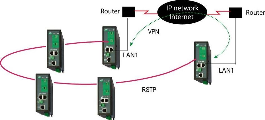
The XSLAN+ SHDSL switch is designed and manufactured by

                         ETIC TELECOM
                        13 Chemin du vieux chêne
                             38240 MEYLAN
                                FRANCE

                       TEL : + (33) (0)4-76-04-20-05
                     E-mail : hotline@etictelecom.com
                       web : www.etictelecom.com

Page 2                                                  DOC_DEV_XSLAN+_User guide_B
DECLARATION OF CONFORMITY
The manufacturer, ETIC Telecom – 13 chemin du vieux chêne – 38240 Meylan – France, Hereby declares
under sole responsibility that the listed products conform to
   -    the Electromagnetic Compatibility (EMC) Directive 2014/30/UE ,
   -    the Low Voltage Directive (LVD) 2014/35/UE ,
   -    the Restriction of the use of certain Hazardous Substances (RoHS) Directive 2011/65/UE.

Type of product:    SHDSL switch
Models:
XSLAN+140
XSLAN+1400, XSLAN+1220, XSLAN+1230, XSLAN+1260, XSLAN+1261
XSLAN+2400, XSLAN+2220, XSLAN+2230, XSLAN+2260, XSLAN+2261
XSLAN+BP2400, XSLAN+BP2220, XSLAN+BP2230, XSLAN+BP2260, XSLAN+BP2261
XSLAN+4400, XSLAN+4220, XSLAN+4230, XSLAN+4260, XSLAN+4261

The harmonized standards to which these products comply are:

Standard                     Title
EN 61000-6-2 2006            Immunity:
                             EN61000-4-2 Electrostatic Discharge
                             EN61000-4-3 RF Radiated Immunity
                             EN61000-4-4 EFT/Burst Immunity
                             EN61000-4-5 Surge Immunity
                             EN61000-4-6 RF Conducted Immunity
                             EN61000-4-8 Power Frequency Magnetic Field Immunity

EN 61000-6-4 2007            Emission:
A1/2011                      EN55022 Radiated and conducted emission
EN 60950-1/A2 2014           Safety and Health

Date : 11th October 2017

Philippe Duchesne
Technical Director

NOTE:

This equipment has been tested and found to comply with the limits for a Class A digital device, pursuant to
Part 15 of the FCC Rules. These limits are designed to provide reasonable protection against harmful
interference when the equipment is operated in a commercial environment. This equipment generates, uses,
and can radiate radio frequency energy and, if not installed and used in accordance with the instruction
manual, may cause harmful interference to radio communications. Operation of this equipment in a
residential area is likely to cause harmful interference in which case the user will be required to correct the
interference at his own expense.

DOC_DEV_XSLAN+_User guide_B                                                                            Page 3
TABLE OF CONTENTS

OVERVIEW..................................................................................................................................... 7
1    Purpose of this manual .................................................................................................................................... 7
2    Products identification ..................................................................................................................................... 7
3    Specifications.................................................................................................................................................... 8
4    Product overview ............................................................................................................................................ 10
     4.1       XSLAN+1XXX ....................................................................................................................................... 10
     4.2       XSLAN+2XXX ....................................................................................................................................... 10
     4.3       XSLAN+4200 ........................................................................................................................................ 12
5    Highlighted features ....................................................................................................................................... 14
     5.1       STU-C / STU-R auto-negotiation ......................................................................................................... 14
     5.2       Redundancy solutions: RSTP and proprietary failsafe ring ............................................................... 14
     5.3       The by-pass function ........................................................................................................................... 15
     5.4       The loop VPN function ........................................................................................................................ 15
     5.5       Other functions of the XSLAN+ family ............................................................................................... 16

INSTALLATION ........................................................................................................................... 17
1    Description ...................................................................................................................................................... 17
     1.1       Dimensions .......................................................................................................................................... 17
     1.2       Connectors ........................................................................................................................................... 17
     1.3       Push button .......................................................................................................................................... 22
     1.4       LED indicators ...................................................................................................................................... 23
2    Safety instructions .......................................................................................................................................... 24
3    DIN rail mounting ............................................................................................................................................ 25
4    Cooling ............................................................................................................................................................. 25
5    Power supply ................................................................................................................................................... 25
6    Isolation and earthing ..................................................................................................................................... 26
7    RS232 serial connection (XSLAN+X220 or XSLAN+X230) .......................................................................... 26
8    RS485 serial connection (XSLAN+X220) ...................................................................................................... 26
9    RS422 isolated serial connection (XSLAN+X260) ........................................................................................ 27
10      RS485 isolated serial connection (XSLAN+X261) .................................................................................... 28
11      Digital input and output............................................................................................................................... 29
12      Preparing and checking the line ................................................................................................................. 29
     12.1          Type of cable .................................................................................................................................... 29
     12.2          Crosstalk interference ..................................................................................................................... 30
     12.3          Shield earthing ................................................................................................................................. 30
     12.4          Protecting the SHDSL switch from lightning.................................................................................. 30
13      Connecting the XSLAN+ to the line ............................................................................................................ 30
     13.1          General precautions ......................................................................................................................... 30
     13.2          Point to point connection using two, three or four twisted pairs .................................................. 31
     13.3          Daisy chain or ring connection ........................................................................................................ 31
     13.4          By-pass function .............................................................................................................................. 31

PREPARING THE SETUP ............................................................................................................ 33
1    Connecting a PC for configuration ................................................................................................................ 33

DOC_DEV_XSLAN+_User guide_B                                                                                                                                     Page 5
TABLE OF CONTENTS

     1.1       Overview ............................................................................................................................................... 33
     1.2       First configuration ............................................................................................................................... 34
     1.3       Changing the configuration later ........................................................................................................ 34
2    Temporary return to the factory settings ...................................................................................................... 35
3    Restoring the factory settings ........................................................................................................................ 35
4    Protecting the access to the administration server ...................................................................................... 36
5    Configuration steps ........................................................................................................................................ 36

ANNEX 1 : SHDSL data rate versus distance ........................................................................... 37

Page 6                                                                                                               DOC_DEV_XSLAN+_User guide_B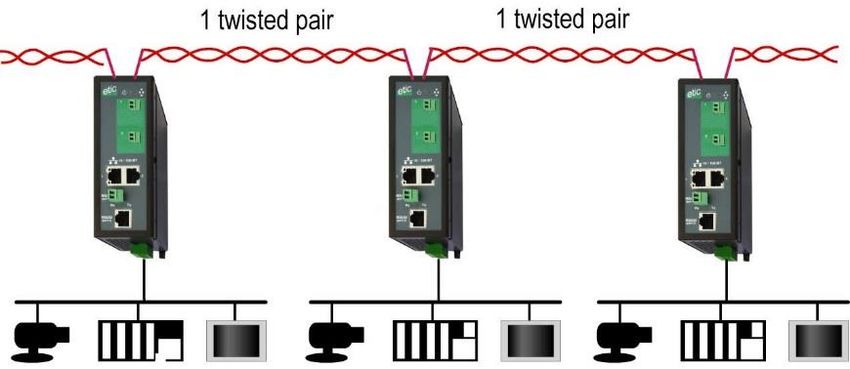
OVERVIEW

OVERVIEW
1        Purpose of this manual

The present user guide describes the features and the installation of the XSLAN+ switches family (it also
applies to the switches family previously named XSRING+).

2        Products identification

The XSLAN+ is an industrial Ethernet switch that provides 1 to 4 SHDSL ports to extend the Ethernet
transmission up to several kilometers using any existing copper pair.

The XSLAN+ switches family consists of these models :

XSLAN+1400, XSLAN+1220, XSLAN+1230, XSLAN+1260, XSLAN+1261
XSLAN+2400, XSLAN+2220, XSLAN+2230, XSLAN+2260, XSLAN+2261
XSLAN+BP2400, XSLAN+BP2220, XSLAN+BP2230, XSLAN+BP2260, XSLAN+BP2261
XSLAN+4200, XSLAN+BP4200

The main features are summarized hereafter :

                                                 XSLAN+ models
                                   1400   12xx      2400   22xx    BP2400 BP22xx   4200    BP4200
    SHDSL port                      1      1         2       2       2      2       4        4
    Max. data rate (Mb/s)          15.2   15.2      30.4   30.4     30.4   30.4    60.8     60.8
    Ethernet port 10-100 Mb/s       4      2         4       2       4      2       2        2
    RS232/RS485 *                   N      Y         N       Y       N      Y       N        N
    By-pass                         N      N         N       N       Y      Y       N        Y
    Failsafe ring                   N      N         Y       Y       Y      Y       Y        Y
    Serial gateway                  N      Y         N       Y       N      Y       N        N
    raw, telnet, modbus,
    unitelway

*Models with serial interface code :

          xx               RS232          RS485          RS422         RS485
                                                        isolated      isolated
          20                 1              1               0             0
          30                 2              0               0             0
          60                 0              0               1             0
          61                 0              0               0             1

DOC_DEV_XSLAN+_User guide_B                                                                      Page 7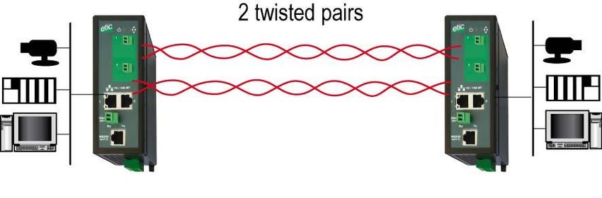
OVERVIEW

3      Specifications

Dimensions              136 x 48 x 138 mm (h, l, p)

Weight                  Max 0.74 kg

Casing                  Metallic
                        IP20 – IEC60529
                        DIN rail mounted

Temperature             Storage: - 40°/ + 85°C
                        Operating: - 40°/ + 70°C
Humidity                10 to 95 % (relative)

Power supply            2 power supply inputs
                        Reverse polarity protection
                        Nominal : 12-48 VDC (min 10 VDC - max 60 VDC)

Consumption             XSLAN+1400 or +12xx : 5W
                        XSLAN+2400 or +22xx : 6W
                        XSLAN+4200 : 9W

EMC                     Susceptibility EN61000-6-2 :
                           ESD : EN61000-4-2 : 4 kV contact – 8kV air
                           RF radiated : EN61000-4-3 : 10V/m < 2 GHz
                           Burst : EN61000-4-4
                           Surge : EN61000-4-5 : 4KV line / earth
                           RF conducted : EN61000-4-6
                           Magnetic fields : EN61000-4-8
                        Emission conducted and radiated :
                            EN 55022

Electrical safety       EN 60950-1

                        2011/65/UE (RoHS)
Hazardous materials
                        REACH

SHDSL                   ITU-T G.991.2, 802.3ah : 2BaseTL (EFM)
                        Data rate: 192 kb/s to 15,2 Mb/s on 1 pair
                        Isolation 1500 V
                        Connection time: 45 s typical
                        STU-C / STU-R auto-negotiation

Latency                 Frame transmission delay from one Ethernet port of an XSLAN+ to the Ethernet port of another
                        XSLAN+ through an SHDSL link : 4 ms at 5.6 Mb/s

Ethernet                10/100 Mb/s Half/Full duplex Auto MDI/MDIX

Switch                  Store and forward - 1024 addresses MAC

Redundancy              RSTP - IEEE 802.1D / 802.1Q
                        Fail safe ring
                        Loop VPN

VLAN                    IEEE 802.1Q

IP address              IPV4 and IPV6

IP router               Multicast and broadcast filtering
                        Static routes
                        RIP V2 - OSPF

Page 8                                                                          DOC_DEV_XSLAN+_User guide_B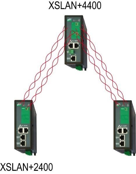
OVERVIEW

QOS                     RFC 2474, 2475, 2597, 2598 « Differentiated services »
                        Traffic prioritization and bandwidth reservation

SNMP                    Supported MIBS :
                        RFC1213-MIB (MIB-2)
                        HDSL2-SHDSL-LINE-MIB
                        HOST-RESOURCES-MIB / IF-MIB
                        IP-MIB
                        BRIDGE-MIB
                        RSTP-MIB

RS232-RS485 *           Asynchronous - 1200 à 115200 kb/s with or without parity
                        Gateway : Raw TCP client and server / UDP multipoint / Multicast / Telnet
                        Modbus / Unitelway

Date and time           NTP client and server

Log                     Log with timestamp of the last 300 events
                        Syslog
Alarm                   1 digital output
                        SNMP traps

Configuration           With HTML browser

* depending on models

DOC_DEV_XSLAN+_User guide_B                                                                             Page 9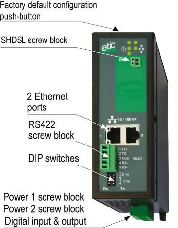
OVERVIEW

4     Product overview

The XSLAN+ switches family includes :

The products which can be connected to only one twisted pair.
They only provide one SHDSL interface.
The references of that products are XSLAN+1400 or XSLAN+12xx if they provide a serial port.
They are named XSLAN+1XXX hereafter.

The products which can be connected to two twisted pair.
They provide two SHDSL interfaces.
The references of that products are XSLAN+2400 or XSLAN+22xx if they provide a serial port.
They are named XSLAN+2XXX hereafter.

The products which can be connected to four twisted pair.
They provide four SHDSL interfaces.
The references of that products are XSLAN+4200.

4.1    XSLAN+1XXX

Point to point link on a single twisted pair

Two XSLAN+1XXX extend Ethernet over one
twisted pair.
The data rate is up to 5,7 Mb/s on 3,7 Km and 15
Mb/s on 0,7 Km (see table in Annex 1).

4.2    XSLAN+2XXX

Additional features compared to XSLAN+1XXX:

Point to point link on two twisted pairs

Two XSLAN+2XXX extend Ethernet over two
aggregated twisted pair.

The data rate is twice the data rate on a single
pair: up to 11,4 Mb/s on 3,7 Km and 30 Mb/s on
0,7 Km (see table in Annex 1).

Page 10                                                                 DOC_DEV_XSLAN+_User guide_B
OVERVIEW

In case of a failure of a pair the data
transmission is maintained on the other pair
(backup).

Daisy chain link

The XSLAN+2XXX is used to
interconnect a series of Ethernet
networks using a single twisted pair.
Thanks to the Store and Forward
principle, the number of switches is
not limited.

Point to multipoint link

The XSLAN+2XXX is used to interconnect a central site with two
remote sites.

DOC_DEV_XSLAN+_User guide_B                                         Page 11
OVERVIEW

RSTP redundant link of fail safe ring

Redundant network ring using the proprietary
protocol (or RSTP)

Complex network topology and "multi-
manufacturer" using the RSTP standard
protocol.

4.3    XSLAN+4200

Additional features compared to XSLAN+2XXX:

Point to point link on four twisted pairs

Two XSLAN+4200 extend Ethernet over two, three or four
aggregated twisted pair.

The data rate is the sum of the data rate on each pair: up to
22,8 Mb/s on 3,7 Km and 60 Mb/s on 0,7 Km (see table in
Annex 1).

In case of a failure of one or more pairs, the data transmission
is maintained on the remaining pairs (backup).

Page 12                                                            DOC_DEV_XSLAN+_User guide_B
OVERVIEW

Point to multipoint link - Concentrator

The XSLAN+4200 is used to interconnect a
central site with four remote sites.

Point to multipoint link with doubled data rate

The XSLAN+4200 is used to interconnect a central site with two
remote sites.

Redundant ring with doubled data rate

Redundant ring with         2    pairs
aggregated on each side.

DOC_DEV_XSLAN+_User guide_B                                         Page 13
OVERVIEW
5 Highlighted features
5.1 STU-C / STU-R auto-negotiation
When two XSLAN+ are connected by a twisted pair, one switch initiates the connection while the other
responds and adapts automatically its data rate.
The switch that initiates the connection is called STU-C.
The switch that responds and adapts is called STU-R.
Thus a line is always connected on one side to a switch acting as the STU-C and on the other side to a
switch acting as the STU-R.
STU-C STU-R
The STU-C switch The STU-R switch
negociates the data 1 twisted pair automatically adapts
rate
One switch is normally configured as a STU-C and the other as a STU-R. However, to make the configuration
simpler, the switch configured as a STU-C is able to automatically change to STU-R mode if it detects the
presence of a STU-C on the remote side. Thus, two XSLAN+ configured both in STU-C will find a way to
connect. One of the two will switch to STU-R.
5.2 Redundancy solutions: RSTP and proprietary failsafe ring
Industrial applications need reliable networks; one way to provide reliability is to provide backup paths which
form loops in the Ethernet network.
However, loops are highly unwelcome in Ethernet networks, as they can cause broadcast storms, eating up all
the available bandwidth and causing network outage.
The goal of redundancy protocols is to make Ethernet work of networks containing loops and to provide a path
at each time, even, if possible, when one or several links are in failure.
The XSLAN+ provides two solution to handle redundancy :
RSTP :
RSTP, standing for "Rapid Spanning Tree Protocol" is specified by the IEEE in the 802.1D-2004 document.
RSTP can handle complex structures ; RSTP can be used with devices from other manufacturers.
The failure detection delay and the recovery delay in an SHDSL network is around 10 seconds.
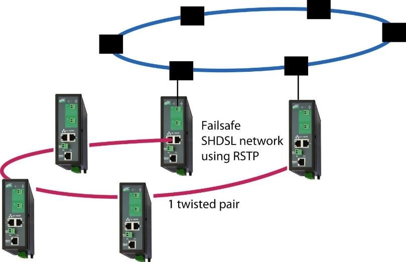
Page 14 DOC_DEV_XSLAN+_User guide_BOVERVIEW Proprietary failsafe ring algorithm: Based on the STP algorithm, that solution makes possible to handle a ring structure up to 16 SHSDL switches. The advantages of that solution is that the failure detection delay and the recovery delay is only a few seconds (One second if the ring counts 5 SHDSL switches); moreover, it is very simple to configure. 5.3 The by-pass function When the network is a daisy chain – that case is very frequent in industrial applications - and when, however, it is not possible to build a failsafe structure like a ring, the XSLAN+BP offers a very useful function called the “By-pass function”. The XSLAN+BP includes an electro-mechanical relay between both lines; that relay is automatically closed to connect the two lines when the XSLAN+BP is switched off. For instance, if the XSLAN+ #2 cabinet is switched off for maintenance, the by-pass relay inside the XSLAN+ #2 will automatically connect the line coming from the XSLAN+ #1 to the line going to the XSLAN+ #3. After a few seconds, the XSLAN+ #1 detects the connection default and establishes immediately the connection with the XSLAN+ #3. 5.4 The loop VPN function When the SHDSL network forms a daisy chain (ie a linear topology), and when it is not possible to form a secure ring, the "loop VPN" function allows for network redundancy if a public WAN connection (Internet) or private (MPLS) is available at each end of the SHDSL network. DOC_DEV_XSLAN+_User guide_B Page 15
OVERVIEW

The 2 XSLAN+ at the end of the
network establish a VPN over the
WAN.     The      VPN    provides
connectivity at the Ethernet level.
Thus by activating the RSTP
protocol redundancy may be
provided thanks to that VPN.

5.5     Other functions of the XSLAN+ family

Data rate versus distance
The table in Annex 1 gives the data rate which can be expected over a line versus the length of the line.
Each interface features an adaptive data rate from 192 Kb/s up to 15,2 Mb/s.

When using several aggregated pairs, the total data rate that can be obtained is equal to the sum of the data
rates on each pairs.

Ethernet and serial interface
Depending on the model, the products have either 4 RJ45 Ethernet interfaces, or 2 Ethernet and 1 or 2 serial
interfaces associated with a gateway function that allows the easy integration of equipment with RS232 or
RS485 or RS422 serial interface to the Ethernet network.

IP routing and filtering
The XSLAN+ can remove the broadcast frames on the SHDSL link by routing the IP frames, and thus limiting
the unwanted traffic on the SHDSL link.

VLAN
The XSLAN+ features VLAN :
Each Ethernet port can be assigned to a particular VLAN. A device connected to an Ethernet port belonging to
a particular VLAN can communicate only with devices connected to Ethernet ports belonging to the same one.

Quality of service DiffServ
The XSLAN+ can manage different IP traffics with different priorities.

SNMP
The XSLAN+ can be monitored by an SNMP manager and supports the main MIB of an Ethernet switch and
the SHDSL MIB.

Configuration
The products are configured with an html browser.

Page 16                                                                      DOC_DEV_XSLAN+_User guide_B
INSTALLATION

INSTALLATION
1       Description

1.1      Dimensions

    All models XSLAN+1XXX or XSLAN+2XXX or XSLAN+4200

                                                           The height indicated ignores the
                                                           bulk of the power connector on the
                                                           bottom side.

1.2      Connectors

    XSLAN+1400                                XSLAN+1220

DOC_DEV_XSLAN+_User guide_B                                                          Page 17
INSTALLATION
XSLAN+1230 XSLAN+1260
XSLAN+1261
XSLAN+2400
For XSLAN+22XX :
See XSLAN+12XX
Page 18 DOC_DEV_XSLAN+_User guide_BINSTALLATION
XSLAN+BP2400
For XSLAN+BP22XX :
See XSLAN+12XX
XSLAN+4200
XSLAN+BP4200
The By-passed ports are port 3 and port 4 only.
DOC_DEV_XSLAN+_User guide_B Page 19INSTALLATION
Ground terminal
Symbol Description
FASTON male lug 6.35 mm
2 positions screw terminal: Supply voltage 1
Position 1 at back - Protected against reverse polarity
Position Signal Function
1 Power 1 + +V : 12 – 48 V DC
2 Power 1 - 0V isolated from the enclosure
2 positions screw terminal: Supply voltage 2
Position 1 at back - Protected against reverse polarity
Position Signal Function
1 Power 1 + +V : 12 – 48 V DC
2 Power 1 - 0V isolated from the enclosure
4 positions screw terminal: Digital input and output
Position 1 at back
Position Signal Function
1 3V3 3 V DC provided by the XS+
2 In Digital input
3 F+ Digital output + (max 48Vdc - 0,5A)
4 F- Digital output -
XSLAN+1XXX or XSLAN+2XXX or XSLAN+4200
2 positions screw terminal :
SHDSL1 & SHDSL2 & SHDSL3 & SHDSL4
Position Signal Function
1 Line SHDSL line conductor
2 Line SHDSL line conductor
XSLAN+BP2XXX
2 positions screw terminal :
SHDSL1 & SHDSL2 & SHDSL1 by_pass & SHDSL2 by-pass
Position Signal Function
1 Line SHDSL line conductor if the by-pass function is used
2 Line SHDSL line conductor if the by-pass function is used
XSLAN+BP4200
2 positions screw terminal :
SHDSL1 & SHDSL2 & SHDSL3 by_pass & SHDSL4 by-pass
Position Signal Function
1 Line SHDSL line conductor if the by-pass function is used
2 Line SHDSL line conductor if the by-pass function is used
Page 20 DOC_DEV_XSLAN+_User guide_BINSTALLATION
Ethernet RJ45 connector
Position Signal Function RJ45
1 Tx + Emission polarity +
2 Tx - Emission polarity -
3 Rx + Reception polarity +
4 N.C -
5 N.C -
6 Rx - Reception polarity -
7 N.C. -
8 N.C. -
XSLAN+X220
2 positions screw terminal: RS485
Position Signal Function
1 A RS485 polarity A
2 B RS485 polarity B
XSLAN+X261
3 positions screw terminal: RS485 isolated
Position Signal Function
1 Com Common isolated
2 B (+) RS485 polarity B
3 A (-) RS485 polarity A
XSLAN+X260
5 positions screw terminal: RS422 isolated
Position Signal Function
1 Tx+ Emission polarity +
2 Tx- Emission polarity -
3 Com Common isolated
4 Rx+ Reception polarity +
5 Rx- Reception polarity -
XSLAN+X220 et XSLAN+X230
RJ45 connector: RS232
To connect a DCE
Position Signal Direction Function RJ45
1 DTR - 108 OUT Data terminal ready
2 TD - 103 OUT Data Emission
3 RD - 104 IN Data Reception
4 DSR - 107 IN Data set ready
5 SG - 102 - Ground
6 Not used OUT -
7 CTS - 106 IN Clear to send
8 RTS - 105 OUT Request to send
OUT = Signal supplied by the XSLAN+.
IN = Signal supplied by the external device.
DOC_DEV_XSLAN+_User guide_B Page 21INSTALLATION
IPL-X-220 et IPL-X-230
RJ45 connector: RS232
To connect a DTE
Position Signal Direction Function RJ45
1 CD - 109 OUT Carrier detect
2 RD - 104 OUT Data Reception
3 TD - 103 IN Data Emission
4 DTR - 108 IN Data terminal ready
5 SG - 102 - Ground
6 DSR - 107 OUT Data set ready
7 RTS - 105 IN Request to send
8 CTS - 106 OUT Clear to send
OUT = Signal supplied by the XSLAN+.
IN = Signal supplied by the external device.
1.3 Push button
Push-button
Pressing the PB LED Function
During operation Flashing red Temporary return to the factory configuration.
(IP address 192.168.0.128)
The current configuration is not lost.
During power-up Flashing red Return to the factory configuration.
The current configuration is deleted except if it has been saved
into a file.
Page 22 DOC_DEV_XSLAN+_User guide_BINSTALLATION
1.4 LED indicators
LED indicators
Depending on models
Function LED Description
Power 1 Steady green: The supply voltage 1 is present
Power 2 Steady green: The supply voltage 1 is present
Steady green: The unit is ready
Slow blinking green: The unit is busy
Run Steady red: Startup (15 s) – Otherwise : product failure
Fast blinking red: Firmware download in progress
Steady green: The fail safe ring is established
Ring Steady red: Fail safe ring failure
Off: Fail safe ring disabled
SHDSL 1 Green light:
SHDSL 2 Slow blinking: Connection in progress
1 to 4
SHDSL 3 Steady: Connection established
SHDSL 4 Flashing: Traffic on the link
RS232 * Rx Bytes received from the RS232
Tx Bytes transmitted to the RS232
RS485 * Rx Bytes received from the RS485
Tx Bytes transmitted to the RS485
RS422 * Rx Bytes received from the RS422
Tx Bytes transmitted to the RS422
* Depending on models
DOC_DEV_XSLAN+_User guide_B Page 23INSTALLATION
2 Safety instructions
The product shall be installed in a fire electrical resistant cabinet by a qualified operator.
The product shall be connected only to equipments that comply with the IEC60950-1 or IEC62368-1 standards
and that meet the following classifications:
• IEC60950-1 : Limited power circuits and SELV type – §2.2 and 2.5
• IEC62368-1 : ES1 & PS2
To avoid any risk of burns, it is strongly recommended to wear gloves to handle the product in
operation when the ambient temperature exceeds 30 °C.
Page 24 DOC_DEV_XSLAN+_User guide_BINSTALLATION 3 DIN rail mounting Mounting the unit on the 35 mm horizontal DIN rail, Removing the unit from the DIN rail, 4 Cooling The product is designed to be mounted on a 35mm DIN rail. To avoid obstructing the airflow around the unit, the spacing must be at least 25 mm above and below, and 10 mm left and right. 5 Power supply The XSLAN+ has 2 power inputs allowing a redundancy power supply. The supply voltage must be regulated and strictly between 10 and 60 Volt DC (nominal : 12 – 48 VDC). The power consumption is 5W for XSLAN+1XXX, 6W for XSLAN+2XXX+ and XSLAN+BP2XXX and 9W for XSLAN+4XXX. DOC_DEV_XSLAN+_User guide_B Page 25
INSTALLATION

6       Isolation and earthing

The enclosure of the XSLAN+ is metallic ; For safety and EMC reasons, the ground terminal (on the underside)
must be connected to the protective earth of the installation.

The minus polarity of the supply voltage is common with the minus voltage of the electronic board (usually
called 0V) and is isolated from the enclosure.

Ethernet and SHDSL signals are isolated through transformers. Consequently,

     XSLAN+X400, XSLAN+BP2400, XSLAN+X260 et XSLAN+X261 products are electrically isolated from the
     outside up to a common mode voltage of 1500 V;
     XSLAN+X220 et XSLAN+BP2220 products are electrically isolated with the same conditions except for the
     RS232 and RS485 interfaces;
     XSLAN+X230 et XSLAN+BP2230 products are electrically isolated with the same conditions except for the
     RS232 interfaces;

7       RS232 serial connection (XSLAN+X220 or XSLAN+X230)

Cables can be provided to connect the product to DTE and DCE as follows :

                                       RS232 cables
    Reference        Connector                               Function
    CAB592      SubD 9 male            To connect a DCE to the product
    CAB593      SubD 9 female          To connect a DTE to the product
    CAB609      Wires                  To connect a device providing a specific connector

The RS232 cable must be shorter than 10 meters.

8       RS485 serial connection (XSLAN+X220)

The RS485 interface is not isolated.

Two 10 KOhm bus polarization resistors are included inside the product.

if the RS485 line is longer than10 meters or if the data rate is greater than
                                                                                  +                            -
19200 b/s, it is necessary to connect one 120 Ohm matching resistor at            10 KOhm
                                                                                                   A(-)
                                                                                                          10 KOhm
                                                                                            B(+)
each end of the line and two 390 Ohm polarization resistors at one of the
                                                                                              RS485
two extremities of the line.

Page 26                                                                          DOC_DEV_XSLAN+_User guide_B
INSTALLATION
9 RS422 isolated serial connection (XSLAN+X260)
The polarization and termination resistors can be selected with
DIP switches.
The termination resistor must be enabled when the product is
located at the extremity of the RS422 bus.
The polarization resistors must be enabled by one device of the
bus.
Up to 16 devices can be connected to the bus.
We recommend to use a shielded cable and twisted pairs.
When two devices or more are connected to the RS422 bus, the
XSLAN+ must be the only device to transmit data on the TX+/TX-
line towards all the other devices.
It means that the TX+/TX- line of the IXSLAN+ must be connected
to the RX+/RX- of all the other devices of the bus.
Micro-switches
No polarization
No termination resistor
470 Ohm polarization resistors
No termination resistor
No polarization
120 Ohm termination resistor
470 Ohms polarization resistors
120 Ohm termination resistor
All other combinations are prohibited
DOC_DEV_XSLAN+_User guide_B Page 27INSTALLATION
10 RS485 isolated serial connection (XSLAN+X261)
The polarization and termination resistors can be selected with
DIP switches.
The termination resistor must be enabled when the product is
located at the extremity of the RS485 bus.
The polarization resistors must be enabled by one device of the
bus.
Up to 16 devices can be connected to the bus.
We recommend to use a shielded cable and twisted pairs.
Micro-switches
No polarization
No termination resistor
470 Ohm polarization resistors
No termination resistor
No polarization
120 Ohm termination resistor
470 Ohms polarization resistors
120 Ohm termination resistor
All other combinations are prohibited
Page 28 DOC_DEV_XSLAN+_User guide_BINSTALLATION
11 Digital input and output
Digital output :
Isolated 500 V
Max. voltage : 48 VDC Digital output
Digital input
Max. current : 500 mA
3V3 In F+ F-
Digital input :
5 6 7 8
Not isolated +
V
Maximum voltage : 20 VDC
-
I max = 0,5 A V < 48 VDC
I < 0,5 A
12 Preparing and checking the line
12.1 Type of cable
Twisted pair cable
The XSLAN+ SHDSL switch is designed to be connected to one or several telephone grade twisted pairs.
The conductor diameter must be included between 0.4 mm and 1 mm.
A cable may be composed of several twisted pairs.
Each pair can usually be used for a different SHDSL transmission if necessary. However, care must be taken
to ensure that crosstalk between pairs is not excessive.
Cable made of quads
It often happens that the twisted pairs of the same cable are wound in groups of two pairs; a group of two
pairs rolled into each other is called a quad.
This type of cable is suitable. However, we will try to use only one pair per quad to avoid crosstalk (see below).
Shielded cable
It is better to use a shielded cable.
The shield must be connected to the earth at one of its ends.
The shield decreases the influence of the electromagnetic ambient noise on the SHDSL signal.
Moreover, the shield protects the XSLAN+ against lightning.
Electrical power cable
Two power conductors can be used instead of a twisted pair to set an SHDSL connection.
However, because the two wires are not twisted, the ambient electrical noise may disturb the transmission.
Compared to the transmission over a twisted pair, the maximum distance between two SHDSL switches is
decreased.
DOC_DEV_XSLAN+_User guide_B Page 29INSTALLATION 12.2 Crosstalk interference If the cable is made of several pairs, each pair can be used to transmit a particular SHDSL connection ; however the SHDSL signal transmitted in one pair may disturb the SHDSL signal transmitted in another one, and, in some cases, may decrease the effective data rate of both SHDSL connections. The closer the pairs, the greater the crosstalk. Thus the risk of crosstalk is higher between two pairs of the same quad. This is why, if the cable is made up of quads, it is advisable to avoid using the two pairs of the same quad. 12.3 Shield earthing A shielded cable provides better noise immunity and surges protection during thunderstorms. The best protection is provided when the shield is earthed at each end of the line. However, there may be a large potential difference between the connection points to the earth, especially when the line is long. Therefore, to avoid a large current flowing in the shield, it is recommended to connect the shield to the earth at only one end of the cable. 12.4 Protecting the SHDSL switch from lightning The XSLAN+ is coupled to the line by a transformer which provides isolation between the circuit board and the line. Moreover, the XSLAN+ is equipped with internal protections against overvoltage. However, if the line is vulnerable to thunderstorms, for example if it is an air line, or if it is several kilometers long, or if the installation is in a very exposed area, it is recommended to protect each XSLAN+ with a surge protector, as described below. 13 Connecting the XSLAN+ to the line 13.1 General precautions The SHDSL signal is not polarized ; it is why the two conductors of one line can be inverted. Check that the shield, if any, is properly connected to the ground. Page 30 DOC_DEV_XSLAN+_User guide_B
INSTALLATION

13.2    Point to point connection using two, three or four twisted pairs

An aggregated link is a link between two XSLAN+ that uses two or three or four twisted pairs to multiply the
total throughput (depending on model).

When performing a point to point link to doubled (XSLAN+2XXX) or tripled or quadrupled (XSLAN+4200) the
data rate, it is recommended to wire pairs in an orderly way, as shown below, to make the configuration and
the diagnostic easier.

   XSLAN+4XXX                                   XSLAN+4XXX

13.3    Daisy chain or ring connection

If the SHDSL switches are connected to shape a daisy chain network or a ring network, we recommend to
connect the lines as shown below.

In that way, the configuration of each SHDSL switch will be similar.

13.4    By-pass function

To enable the by-pass function, connect the line1 to the “1
by-pass” screw block and the line 2 to the “2 by-pass”
screw block as shown below.

DOC_DEV_XSLAN+_User guide_B                                                                        Page 31
PREPARING THE SETUP

PREPARING THE SETUP
1     Connecting a PC for configuration

1.1     Overview

The XSLAN+ is configured using a PC with an HTML browser. No additional software is required.

Online help :
For most pages of the administration server an help page is available by clicking ? located at the top right of
the page.

Administration server address :
When the product is delivered, the IP address of the administration web server is 192.168.0.128.

First setup :
For the first configuration, we advise to connect the PC directly to the LAN interface of the XSLAN+.
Subsequent changes can be made remotely.

Restoring the factory IP address :
The factory IP address 192.168.0.128 can be restored (see the User guide of the product).

Restricted access to the administration server :
If you do not have access to the administration server, it is probably that access has been restricted for security
reasons or for other reasons.

Network IP address :
Later in the text, we often speak of “network IP address”. We mean the lowest value of the addresses of the
network.
For instance, if the netmask of a network is 255.255.255.0, the network IP address of that network is
terminated by a zero (X.Y.Z.0.).

Characters allowed
Accented characters are not supported.

DOC_DEV_XSLAN+_User guide_B                                                                              Page 33
PREPARING THE SETUP

1.2     First configuration

Step 1 : Create or modify the PC TCP/IP connection
Assign to the PC an IP address different but consistent with the factory IP address of the XSLAN+.
For the first configuration, assign for instance 192.168.0.1 to the PC.

Step 2 : Connect the PC to the XSLAN+
Connect the PC directly to the XSLAN+ with any Ethernet cable (straight or cross-wired);

Step 3 : Launch the web browser
Launch the web browser and then enter the IP address of the XSLAN+ : 192.168.0.128

The Home page of the administration server is displayed.

Note : Access to the administration server is not protected when configuring the XSLAN+ for the first time.

1.3     Changing the configuration later

Thereafter, the XSLAN+ administration server is accessible from the Ethernet interface or remotely through
the SHDSL line at the IP address assigned to the product.
• Open the html browser and enter the IP address of the administration server of the XSLAN+.
• Enter, if any, the user name and password that protect the access to the administration server.

Page 34                                                                     DOC_DEV_XSLAN+_User guide_B
PREPARING THE SETUP

2     Temporary return to the factory settings

If the IP address of the XSLAN+ could not be founded, or if it is impossible to access the administration server,
for example, following a bad VLAN configuration, it is possible to restore the factory settings without losing
the current configuration.

•   Press the push-button located on the back, for example with a small screwdriver

•   Keep the push-button pressed for about 3 seconds;

•   The RUN LED         blinks red rapidly

•   The administration server becomes accessible at the factory IP address (192.168.0.128), in HTTP without
    a password. The factory configuration is temporarily running. However, the current configuration is not
    lost and it is the one that is still displayed in the pages of the Administration Server.

•   After reading the IP address or changing some parameters, press again the push button (B2) or reboot the
    product.

•   The product can be reached at the registered IP address.

Note :
If the IP address of the XSLAN+ is unknown, the software tool EticFinder can be used.
This software detects all ETIC branded products on a local network. After starting the software, click on the
"Search" button, and when the product list is displayed, double-click on the product address to access the html
server.

3     Restoring the factory settings

It is possible to restore the factory configuration permanently using the push button on the rear panel, or by
using the administration server. In this case, the current configuration will be lost unless it has been saved to
a file.

To restore the factory settings using the push button,
• Power off the XSLAN+,
• Press the push-button, for example with a small screwdriver,
• Power on the XSLAN+, while keeping the push-button pressed at least 10 s.
The RUN led        turns red ; the XSLAN+ boots and the factory configuration is restored.

Note : The factory configuration can also be restored via the menu Maintenance > Configurations
management of the administration server.

DOC_DEV_XSLAN+_User guide_B                                                                            Page 35
PREPARING THE SETUP 4 Protecting the access to the administration server • In the menu, choose Setup > Security > Administration rights • Enter a user name and password to protect the administration server. • Tick the Password protect the web site access checkbox If the username and password to access the administration server are lost, you have to temporarily return to the factory settings; access to the administration server is then free. 5 Configuration steps To configure the product, we advise to proceed as follows : • Set up the LAN interface • Set up the SHDSL connections • Set up the RSTP or failsafe ring redundancy protocol • Set up VLAN • Set up SNMP • Set up QoS • Set up the routing functions • Set up the serial gateways For detail about the configuration and the diagnostics, refer to the XLAN+ / XSMIL Setup Guide : Reference : “DOC_DEV_XS_Setup guide_x” Page 36 DOC_DEV_XSLAN+_User guide_B
ANNEX 1

ANNEX 1 : SHDSL data rate versus distance

The table below shows the data rate which is possible to get on a SHDSL link depending on the wire diameter
and the distance.
These values are indicative in noise free environment.
Distance versus data rate through one pair

 Data rate     192Kb/s     1,2Mb/s    2,3Mb/s    5,7 Mb/s    6.7 Mb/s   10 Mb/s     12 Mb/s    15 Mb/s

 Distance (Ø   13 km       8 km       6 km       3.7 km      2.5 km     1.5 km      1 km       0.7 km
 0.9 mm) *

 Distance (Ø   7 km        4 km       3 km       2 km        1.3 km     0.9 km      0.6 km     0.4 km
 0.4 mm) *

DOC_DEV_XSLAN+_User guide_B                                                                       Page 37
13, Chemin du Vieux Chêne
38240 Meylan - France
Tel : +33 (0)4 76 04 20 00
contact@etictelecom.com
www.etictelecom.com
You can also read