Designing a Graphical User Interface for the Power Module Optimization Tool PowerSynth
←
→
Page content transcription
If your browser does not render page correctly, please read the page content below
2021 ASEE Midwest Section Conference

           Designing a Graphical User Interface for the Power Module
                        Optimization Tool PowerSynth
                          Joshua Mitchenera, Imam Al Razib, Yarui Pengb
                           a
                            Computer Science, University of California, Irvine
                b
                    Computer Science and Computer Engineering, University of Arkansas

    Abstract
Working under the NSF-sponsored POETS REU program, students are given the opportunity to
work at the University of Arkansas on advanced research projects such as the development of a
software tool called PowerSynth, which can optimize power electronic module layout. This is the
first tool that automates the multi-chip power module (MCPM) design flow, and the optimization
results are hardware-validated. The development of a new version of PowerSynth has required the
creation of a new graphical user interface (GUI). A detailed description of the GUIs design flow
and implementation is presented and directly compared to the general command line flow of
PowerSynth. A discussion of the POETS REU program and the role of undergraduate research as
a path to exploring new academic fields is included in its relation to the research completed at
University of Arkansas.

    Keywords
PowerSynth, graphical user interface, power electronics, research experiences for undergraduates,
student paper

 I. Introduction
In the summer of 2021, Joshua Mitchener (the first author of this paper) participated in a Research
Experiences for Undergraduates (REU) program sponsored by the National Science Foundation
and directed by the Engineering Research Center for Power Optimization of Electro-Thermal
Systems (POETS). POETS is a network that seeks to optimize the power-to-weight ratio in all
common electrical and thermal systems, including on-and-off highway vehicles and general
electronics. Over the past two months, visiting undergraduate students have worked at the
University of Arkansas, Fayetteville, alongside a team of graduate students on the PowerSynth
tool.

II. Overview of Power Module Design Flow
Power modules have a variety of practical applications, from use in electric vehicles to personal
computers. As technology continues to improve and the demand for higher-density sources of
power increases, researchers are currently continuing to look for ways to optimize power module
designs [1]. A typical multi-chip power module structure consists of a base plate, an insulating
substrate, bonding materials, power semiconductor chips, power interconnections, encapsulant,
and a case. As more expensive materials such as silicon carbide (SiC), gallium nitride (GaN)
become more widely available for use in power modules, power module fabrication continues to

                            © American Society for Engineering Education, 2021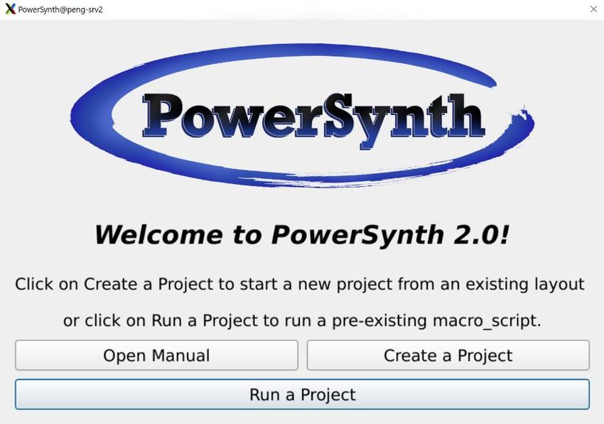
2021 ASEE Midwest Section Conference

                            2D/2.5D/3D Designs, Python 3.8, QT 5.9, Cross-Platform
            Export &      Solution         Netlist         Simulation         Export
           Simulation     Database        Exporting          Export          Functions

                                                                                           Graphical User Interface (GUI)
          Optimization    Genetic       Machine-       Simulated-       Pre/Post-Layout
           Toolbox       Algorithms     Learning       Annealing         Optimization

            Layout        Electrical    Thermal        Reliability     Partial Discharge
           Evaluation      model         model          model                model

             Layout        Constraint             Connectivity              Layout
            Synthesis       (DRC)                   (LVS)                  Generation

                         Object-based layout      MFG Design         Embedded scripting
           Data Input
                           representation          Kit (MDK)           environment

          Design Flow                          PowerSynth 2 Architecture

                                 Fig. 1 PowerSynth 2 architecture
advance in its performance [2]. A power module’s layout is one of the most important features in
establishing its electrical, thermal, and mechanical capabilities. The layout is carefully optimized
based on the materials selected for use in the module, the attachment strategy for connecting wires,
and the layer structure from the base plate to the die and housing [3]. A variety of relatively new
packaging technologies for power modules are currently available to take advantage of the benefits
of wide-bandgap (WBG) devices [5]. However, some of the most common package structures with
SiC devices are inherently limiting to maximizing performance. When creating a power module
layout, finding a balance between electrical parasitics and thermal dissipation is crucial. To
minimize the heat loss, the copper trace area should be as large as possible, yet parasitics must be
minimized by limiting the power loop area. Besides these, mechanical stress and strain factors also
need to be considered for reliable operations. Thus, electro-thermo-mechanical optimization of a
module is essential before fabrication [3]. In the industry, the MCPM design flow is still a manual
and iterative process [11] and takes weeks to complete. However, with the increasing complexity
of the MCPM layouts, the manual design process cannot quickly reach a global optimum solution.
Thus, the development of design automation tools is a goal for power electronics researchers.
Research and development of PowerSynth are on-going to facilitate the designers with a multi-
objective optimization framework that can generate a Pareto-front from a wide variety of solutions
with a significant speedup [9].

III. Overview of the PowerSynth Project
Currently, PowerSynth is a layout synthesis tool for multi-chip power module designs that creates
a variety of optimized designs according to the user’s specified parameters [6]. The tool is created
to address, and combat issues that have arisen as MCPM designs have become denser, resulting in
the signal integrity of power modules becoming more likely to be compromised [7]. While other
software tools, such as the Finite Element Method (FEM) or 3D field solver, that serve a similar
purpose to PowerSynth exist in the market, PowerSynth seamlessly combines layout synthesis

                         © American Society for Engineering Education, 2021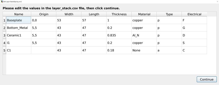
2021 ASEE Midwest Section Conference
with design optimization together into a single process. It is also designed to perform orders of
magnitude more efficiently with a minimal cost to the accuracy of results. For example, other tools
or methods for optimizing a design may take weeks to complete, whereas an experienced user of
PowerSynth can optimize a layout within hours [6].
Though the previous versions of PowerSynth had a GUI to assist the user with the process of using
the tool [9], a new PowerSynth 2 series is currently in development, introducing new features that
require a new interface. This new version of PowerSynth is being built from the ground up and
includes more advanced and efficient algorithms to optimize power module designs. A new
hierarchical structure has been adapted for representing 2D/2.5D/3D MCPM layouts. Thus, it
would be effective to create a new GUI that is both designed to mirror the new architecture (shown
in Fig. 1) and flow of PowerSynth and is able to support the new features offered by the tool.
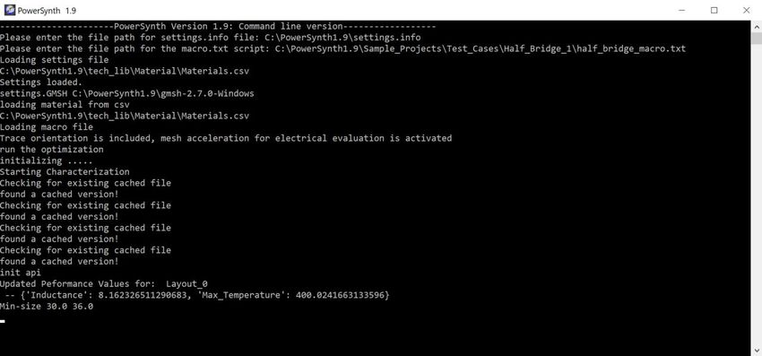
Fig. 2 Screenshot of the current command line version of PowerSynth
IV. Design Flow of Command Line Version
The current command-line version of PowerSynth follows a very simple flow but requires a large
amount of setup. The user must manually create a variety of files to be processed by PowerSynth,
and the paths to these files must be explicitly included in the macro script file. One of the most
important files to be created is the layout script, which contains the hierarchy information of traces,
devices, leads, and all other elements that will make up the specific layout. This file also contains
paths to parts files that specify the attributes of each material. The names of traces and bondwire
in this file will be the reference in the bond wire setup and trace orientation files.
There are two more files required for the main flow of PowerSynth (excluding the macro script
file): the layer stack file and the bond wire setup. The bond wire setup essentially provides the
specifics on the materials, sizes, and placements of the bondwire within the module. The layer
stack is a CSV file that contains the sizes, thicknesses, and materials of different layers in the
module structure. If the user chooses to run layout solution generation with an electrical setup,
then they will also need to create a trace orientation file that denotes the current flow direction
© American Society for Engineering Education, 20212021 ASEE Midwest Section Conference
Fig. 3 The opening window of the new PowerSynth GUI
through the corresponding trace. Even more specifically, if the user runs layout solution generation
with the PowerSynth built-in model, then they must create and reference the path to a pre-compiled
parasitic model file.
Finally, the user must create the macro script file with proper paths to each of the previous files.
This file includes various options for running PowerSynth, including but not limited to the number
of layouts to create, whether to apply reliability constraints, whether to plot the solution, the layout
mode, the randomization seed, and the electrical and thermal setups. The electrical setup requires
a device connection, where the current flow (i.e., drain to source, gate to source, etc.) must be
specified for each device, as well as the general frequency for the layout. Similarly, for the thermal
setup, the user must specify the power for each selected device alongside general parameters such
as heat convection coefficient and ambient temperature.
Edit Materials Create Project Opening Window Run Project Open Project
Optimization Run
Input Layout Edit Constraints
Setup PowerSynth
Edit Layer Stack Edit Constraints Solution Browser Export Solution
Fig. 4 PowerSynth 2 GUI design flow
© American Society for Engineering Education, 20212021 ASEE Midwest Section Conference
With the general setup of a project now completed, the user will first be directed to provide the
necessary configuration information through a text file that contains essential paths for
PowerSynth, including but not limited to where to export data, the path to external models/tools,
the technology library, and the material library. After setting up the environment, the user will be
directed to input the path to their macro script (shown in Fig. 2). Finally, PowerSynth will
automatically create a constraints file and will prompt the user to edit these constraints before
generating solutions. It should be noted that this constraints file can be reused or created by the
user and that this step can be bypassed by setting the “New” flag to 0 in the macro script.
PowerSynth will then run the project and export the created solutions to the specified directory.
V. Design Flow Using the Graphical User Interface
A. Overview
The PowerSynth GUI is implemented as a series of windows created with a QT Framework
(currently implemented through PySide2) that are connected via Python. The flow (shown in Fig.
4) is intentionally designed to require users to proceed linearly through the interface without giving
users the ability to revise any of their input without restarting the GUI. The interface is also
intended to be both simple and functional, only showing what is absolutely necessary to the user
to run PowerSynth. Currently, the PowerSynth GUI is able to edit and track three of the five
required files, with two of the files being automatically generated for the user. Future versions of
the PowerSynth GUI are planned to include more advanced features and implementations.
Fig. 5 Main window of the MDKEditor
© American Society for Engineering Education, 20212021 ASEE Midwest Section Conference
B. Data Input
The opening window of the user interface provides two main flows: to create a project from an
existing layout or to run a project that is already properly configured (Fig. 3). A button to access
the user manual for PowerSynth 1.9 is also provided at this stage. If the user decides to create a
new project, they will be prompted to create or adjust the materials list. They may choose to either
use the default materials or to edit the materials list by opening the MDKEditor (Fig. 5). The
MDKEditor is a material library editor that allows for quick customization and
importing/exporting of materials.
After finalizing the selected materials for their project, the user will be required to enter the paths
(or use the available file explorers) to three required files: the layout geometry description script,
the layer stack, and the bond wire setup information. These files are essential for creating a project,
as each is related to the certain step of describing the initial module design structure. The user is
also prompted to select whether to apply reliability constraints at this stage, as the GUI will
automatically create the constraints file for the user after this window.
Fig. 6 Visualization of the layer stack
C. Layout Synthesis
Assuming all paths are provided correctly, the interface will now provide a visualization of the
input layer stack file (Fig. 6). If the user wishes to make any edits to the layer stack, they can
simply edit this table, and its contents will be written back to the layer stack file for later use.
Similarly, when the user continues, the interface will have created a constraints file for the user
and will show a visualization of this file in the same tabular format as the layer stack (Fig. 7).
© American Society for Engineering Education, 20212021 ASEE Midwest Section Conference
D. Layout Solution Generation/Optimization
Finally, the user will now input the required options for running PowerSynth to be included in the
macro script file. They must first decide how they would like to run the tool, either with initial
layout evaluation, with layout solution generation only, or with optimization. This will determine
what options the interface will present to the user in the next window. Supposing the user selects
both layout optimization and evaluation, the user will be presented with a variety of options to be
adjusted regarding evaluation as well as two buttons to open the electrical and thermal setups (Fig.
8). All the options presented in the GUI at this stage directly correspond to a required line in the
macro script file for running PowerSynth, and the macro script file will be automatically generated
by the interface once all setups have been completed.
Fig. 7 Visualization of the constraints
E. Solution Browser & Export
Now that the macro script file has been created, the GUI will automatically run PowerSynth and
open the solution browser once it is completed (Fig. 9). The solution browser will draw the created
layouts according to the user’s selected parameters (unless initial layout evaluation was chosen, in
which case solutions will be graphed by index), and the user may visualize solutions by clicking
on each point on the graph. This will show the selected solution’s first layer, and the user may view
other layers of the same solution or a combined skeletal visualization of the layers by clicking
between the tabs above the layout. Once the user has selected a solution that they wish to use, they
can export either a specific solution or export all the solutions to a CSV file. This concludes the
main flow for a user to create a project using the PowerSynth GUI.
© American Society for Engineering Education, 20212021 ASEE Midwest Section Conference
Assuming the user already has a macro script file generated, they may choose to run PowerSynth
directly through the GUI. Through this flow, the user will only be prompted to enter the paths for
the macro script and settings.info files—mirroring the flow of the command line interface for
PowerSynth. Finally, the editor presents for the provided constraints file, and after PowerSynth
synthesis completes, the solution browser will display similar to the flow when creating a project.
Fig. 8 Optimization setup window
VI. Undergraduate Research Personal Experience Summary
As an REU student, my time as a POETS REU student this summer has been extremely valuable,
as providing the opportunity to work in a field outside of my general studies in Computer Science
and work outside of my home state at a new university has been a truly extraordinary experience.
Coming from a software background, I have felt somewhat out of place compared to my peers
pursuing undergraduate and graduate degrees in electrical or mechanical engineering. Despite this,
my research project focusing on the development of a GUI for PowerSynth has combined my
general interests in Computer Science with a tangible hardware application. While my task was
focused on software design and programming, research with power module fabrication provided
valuable exposure to advanced topics completely outside of Computer Science. In this way, I
believe that undergraduate research can act as an effective tool for undergraduate students to fully
explore career paths and topics related to, but not necessarily within the scope of their general
studies.
As an inherently uncertain and exploratory time for students, the undergraduate experience in
America is generally not well-built to allow for experimentation in career paths. Students are
expected to select their major out of high school when they apply to college, with the knowledge
that choosing undeclared when applying to a college will have its own deep-seated repercussions.
© American Society for Engineering Education, 20212021 ASEE Midwest Section Conference
Fig. 9 Solution browser window
This difficult yet incredibly important decision often leads to student dissatisfaction and career
anxiety [1]. Changing majors can be extremely difficult to impossible in some cases, perhaps best
represented by some schools utilizing an actual lottery for which students are allowed to change
majors due to excessive demand for popular fields. Thus, perhaps undergraduate research can fill
this gap to allow for increased exploration and mentorship in new fields as the POETS REU
program has for me this summer.
My in-person experience with POETS this summer is in direct contrast with the virtual research I
completed in early 2020. The virtual experience had the advantage of flexibility, but personally
caused greater anxiety due to a lack of effective work-life balance. My in-person experience
provided many more advantages, including more effective networking, better communication
between mentor and mentee, and a much more diverse learning experience. Valuable lessons from
my undergraduate research experience would include the importance of a patient, available mentor,
having a clear and achievable project goal, and the benefits of working outside of one’s comfort
zone. It should be noted that many of the benefits from my experience would likely not have been
possible if the program had been virtual, and the growing acceptance of virtual programs as a
replacement for direct interaction is somewhat concerning. While it is difficult to always guarantee
the ability to perform in-person research given the unpredictability of outside events, it is essential
for in-person research such as my summer experience to stay the norm.
© American Society for Engineering Education, 20212021 ASEE Midwest Section Conference
VII. Conclusion and Future Work
The GUI described in this paper introduces the workflow to the user. It serves as a foundation upon
which more advanced features, tools, and customizations can be added to further refine the design
flow. The new GUI improves user interaction with fundamental design algorithms and data
structures. Integrated into PowerSynth 2, it enhances design efficiency allowing fine-tuning and
visualization of the optimized layout solutions. The goal of the project is to ease the design flow
of PowerSynth for both new and advanced users, and the totality of features effectively achieves
this goal.
Future features that can be added to the interface may include a visualization of the hierarchical
structure of layouts to introduce the underline data structure and algorithms used in the tool. This
will act as further transparency for the user to understand how PowerSynth is generating solutions.
The MDKEditor may also be adapted to edit the layer stack for a project alongside the materials
list. A custom layout editor to create layout script files is also currently in development and will
be linked with the GUI.
Acknowledgment
The authors would like to thank Dr. Alan Mantooth, Tristan Evans, Quang Le, and Shilpi
Mukherjee for their continued support throughout the course of this program. The authors are also
grateful for staff support of the POETS REU program.
This material is based upon work supported by the National Science Foundation under Grant No.
1659794 and EEC-1449548. Any opinions, findings, and conclusions or recommendations
expressed in this material are those of the author(s) and do not necessarily reflect the views of the
National Science Foundation.
© American Society for Engineering Education, 20212021 ASEE Midwest Section Conference
VIII. References
[1] I. A. Razi, D. R. Huitink, and Y. Peng, “PowerSynth-Guided Reliability Optimization of
Multi-Chip Power Module,” in IEEE Applied Power Electronics Conference and Exposition, Jun.
2021, pp. 1516–1523. doi: 10.1109/APEC42165.2021.9487161.
[2] H. Lee, V. Smet, and R. Tummala, “A Review of SiC Power Module Packaging Technologies:
Challenges, Advances, and Emerging Issues,” in IEEE Journal of Emerging and Selected Topics
in Power Electronics, Mar. 2020, pp. 239–255, doi: 10.1109/JESTPE.2019.2951801.
[3] F. Hou et al., "Review of Packaging Schemes for Power Module," in IEEE Journal of
Emerging and Selected Topics in Power Electronics, Mar. 2020, pp. 223-238, doi:
10.1109/JESTPE.2019.2947645.
[4] R. Alizadeh and H. Alan Mantooth, “A Review of Architectural Design and System
Compatibility of Power Modules and Their Impacts on Power Electronics Systems,” in IEEE
Transactions on Power Electronics, Oct. 2021, pp. 11631–11646, doi:
10.1109/TPEL.2021.3068760.
[5] B. Zhang and S. Wang, “A Survey of EMI Research in Power Electronics Systems With
Wide-Bandgap Semiconductor Devices,” in IEEE Journal of Emerging and Selected Topics in
Power Electronics, Mar. 2020, pp. 626–643, doi: 10.1109/JESTPE.2019.2953730.
[6] T. M. Evans, S. Mukherjee, Y. Peng and H. A. Mantooth, "Electronic Design Automation
(EDA) Tools and Considerations for Electro-Thermo-Mechanical Co-Design of High Voltage
Power Modules," in IEEE Energy Conversion Congress and Exposition, 2020, pp. 5046-5052, doi:
10.1109/ECCE44975.2020.9235818.
[7] Q. Le, T. Evans, Y. Peng, and H. A. Mantooth, “PEEC Method and Hierarchical Approach
Towards 3D Multichip Power Module (MCPM) Layout Optimization,” in IEEE International
Workshop on Integrated Power Packaging, Apr. 2019, pp. 131–136. doi:
10.1109/IWIPP.2019.8799081.
[8] Q. Le, I. A. Razi, Y. Peng, and H. A. Mantooth, “PowerSynth Integrated CAD flow for High
Density Power Modules,” in IEEE Design Methodologies Conference, Oct. 2021.
[9] T. M. Evans et al., “PowerSynth: A Power Module Layout Generation Tool,” in IEEE Trans.
Power Electron., Jun. 2019, pp. 5063–5078, doi: 10.1109/TPEL.2018.2870346.
[10] M. M. Nauta, “Assessing College Students’ Satisfaction With Their Academic Majors,” in
Journal of Career Assessment, Nov. 2007, pp. 446–462, doi: 10.1177/1069072707305762.
[11] Imam Al Razi, Quang Le, Tristan Evans, Shilpi Mukherjee, H. Alan Mantooth, and Yarui
Peng, “PowerSynth Design Automation Flow for Hierarchical and Heterogeneous 2.5D Multi-
Chip Power Modules,” in IEEE Transactions on Power Electronics, 2021, pp. 8919–8933,
© American Society for Engineering Education, 20212021 ASEE Midwest Section Conference
Joshua Mitchener
is currently working toward the B.S. degree in Computer Science with a minor in Statistics from
the University of California, Irvine. He is currently working as a POETS REU student at the
University of Arkansas, Fayetteville. His research interests include software development,
advanced programming, and developing software testing tools.
Imam Al Razi
joined in Computer Science and Computer Engineering department at the University of Arkansas
in Fall'2017 as a Ph.D. student. He received his B.Sc. in electrical and electronic engineering (EEE)
from Bangladesh University of Engineering and Technology (BUET), Dhaka, Bangladesh in 2016.
His research interest is in Computer Aided Design (CAD) tool development for power electronics.
Currently, he is working as a POETS (Power Optimization of Electro-Thermal Systems) student
on automated layout synthesis and optimization tool for multi-chip power modules (MCPMs). He
is developing and implementing algorithms for power module layout optimization.
Yarui Peng
received the B.S. degree from Tsinghua University, Beijing, China in 2012. He earned his M.S.
and Ph.D. degrees in Electrical and Computer Engineering from Georgia Institute of Technology,
Atlanta, USA in 2014 and 2016, respectively. He is currently an Assistant Professor in Computer
Science and Computer Engineering Department at University of Arkansas. He also works with the
NSF sponsored Engineering Research Center for Power Optimization of Electro-Thermal
Systems.
His research interests are in the areas of computer-aided design, analysis, and optimization for
VLSI circuits and emerging technologies, such as 2.5D and 3D ICs, high band-gap power
electronics and systems, and high-efficiency digital designs and memory systems. He developed
methodologies and algorithms for parasitic extraction, analysis and optimization for signal
integrity, and alleviating reliability issues in thermal and power delivery in 2.5D and 3D ICs. He
is also working on improving electro-thermal reliability in power systems such as multi-chip power
modules (MCPMs) by performing MCPM layout synthesis and simultaneously optimizing heat
dissipation and electrical performance. He is the recipient of best-in-session award in SRC
TECHCON 14, best student paper award in ICPT 16 and best paper award in EDAPS 17. He is an
NSF CAREER Award winner in 2021.
© American Society for Engineering Education, 2021You can also read