Operator's Manual - Model 36B Compu-Cut Material Cutter - Carpenter MFG
←
→
Page content transcription
If your browser does not render page correctly, please read the page content below
Operator’s Manual

          Model 36B
          Compu-Cut®

      Material Cutter

            Production Wire Processing Equipment

Website: www.carpentermfg.com • Email: wire@carpentermfg.com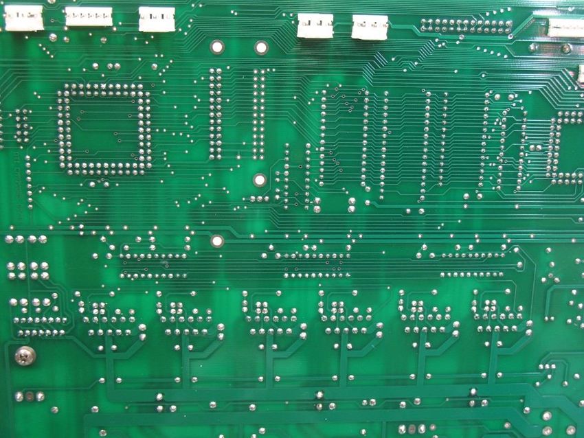
Carpenter Model 36B Compu-Cut®

                                               Table of Contents

Introduction ................................................................................................................... 4
Important Notice ............................................................................................................ 5
Safety and Pneumatic Notices ..................................................................................... 6
Applications and Machine Specifications ................................................................... 7
Section 1 – Initial Machine Setup ................................................................................. 8
   Input and Output Guide Selection ................................................................................ 8
   Input and Output Guide Change .................................................................................. 8
   Loading Material .......................................................................................................... 9
   Feed Belt Pressure .................................................................................................... 10
Section 2 – The LCD Display ...................................................................................... 11
   LCD Display Examples .............................................................................................. 11
Section 3 – Programming ........................................................................................... 13
   Single Cycle ............................................................................................................... 14
   Length Correction ...................................................................................................... 14
   Run Program.............................................................................................................. 14
   Stop Program ............................................................................................................. 14
   Unloading Material ..................................................................................................... 14
   Storing Programs ....................................................................................................... 15
   Recalling Programs.................................................................................................... 15
Section 4 – Special Features ...................................................................................... 16
   Kitting ......................................................................................................................... 16
   Wire Marking .............................................................................................................. 18
   Unit of Measure.......................................................................................................... 18
   Turn Password On/Off ............................................................................................... 18
   Store New Password ................................................................................................. 18
   Wire Stacker .............................................................................................................. 18
   Wire Coiler ................................................................................................................. 19
   Wire Sensor On/Off.................................................................................................... 19
   Representatives Only ................................................................................................. 19
   Reserved.................................................................................................................... 19
Section 5 – Accessory Control .................................................................................. 20

    Carpenter Model 36B Compu-Cut® • Phone: (315) 682-9176 • Fax: (315) 682-9160
           Website: www.carpentermfg.com • Email: wire@carpentermfg.com

Revised 03/10/2021                                                                                                          Page 2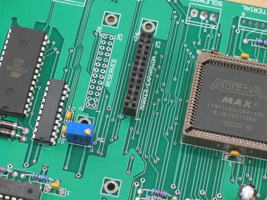
Carpenter Model 36B Compu-Cut®

  Wire Marker ............................................................................................................... 20
  Wire Stacker .............................................................................................................. 22
  Wire Coiler ................................................................................................................. 22
Section 6 – Maintenance Procedures ........................................................................ 24
  Feed Belt Change or Removal ................................................................................... 24
  Blade Change ............................................................................................................ 25
  Machine Lubrication ................................................................................................... 27
Section 7 – Recommended Spare Parts .................................................................... 28
Section 8 – Optional Accessories .............................................................................. 28
  Sleeving Cutter Head Assembly ................................................................................ 28
     Removing Utility Blade Cutter Arm Assembly ......................................................... 29
     Installing Sleeving Cutter Head Assembly .............................................................. 30
     Loading Material ..................................................................................................... 31
     Blade Change ......................................................................................................... 32
     Air Blast Kit for Sleeving Cutter Head Assembly..................................................... 34
  Coiler Accessory Board Kit and External Cable ......................................................... 37
Section 9 – Important Elements for Trouble-Free Operation .................................. 45
Section 10 – Warranty ................................................................................................. 47

    Carpenter Model 36B Compu-Cut® • Phone: (315) 682-9176 • Fax: (315) 682-9160
           Website: www.carpentermfg.com • Email: wire@carpentermfg.com

Revised 03/10/2021                                                                                                     Page 3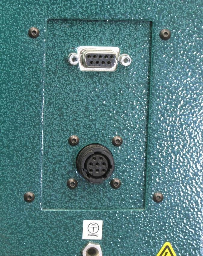
Carpenter Model 36B Compu-Cut®

                                     Introduction
Thank you for choosing Carpenter Mfg. Co., Inc. for your wire processing equipment
needs. For over 60 years Carpenter has been a leader in wire processing technology
and service. As an independently-owned, third generation company our philosophy has
always been to provide the customer with both quality products and outstanding service.
We look forward to a long, healthy relationship with you and our company.

The Model 36B Compu-Cut® can process a wide range of material, as referenced on
the following pages. These processing specifications are based upon the most
commonly manufactured materials. Special applications may arise with materials that
are within the specification limits of the machine but are very difficult or unsuccessful to
process. Likewise, materials that exceed the specified limits of the machine may
sometimes be processed successfully. Because there are many variables involved in
wire processing, we strongly recommend a free material evaluation, to be completed at
our factory (http://carpentermfg.com/wire-evaluation/). A demonstration from a
Carpenter representative is also recommended to ensure the ultimate success of your
material processing application.

This operating manual explains how to operate the Model 36B Compu-Cut®. To ensure
the best performance of your machine, read this manual carefully until you familiarize
yourself thoroughly with its operation and features. After you have read through the
manual, keep it available for reference.

Use this manual as a quick and handy reference tool for clarifying any questions that
may arise. If you have any questions about this machine or service please let us know.
Our phone number is (315) 682-9176; we may also be reached by fax at (315) 682-
9160. Visit our website (www.carpentermfg.com), or contact us via email
(wire@carpentermfg.com).

Carefully unpack the Carpenter Model 36B Compu-Cut®. We recommend that you keep
the original box and packaging as it will protect the machine for future transportation, if
necessary.

   Carpenter Model 36B Compu-Cut® • Phone: (315) 682-9176 • Fax: (315) 682-9160
          Website: www.carpentermfg.com • Email: wire@carpentermfg.com

Revised 03/10/2021                                                                   Page 4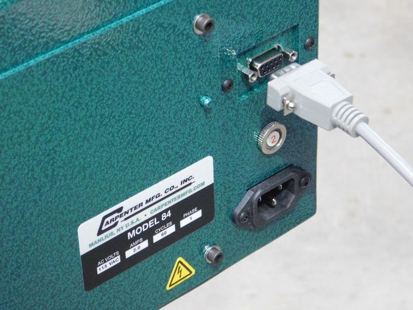
Carpenter Model 36B Compu-Cut®

                                Important Notice
The products in this shipment left our facility in good working condition. Their safe
delivery is the responsibility of the carrier that delivered this shipment to you. Our
stated shipping terms are F.O.B. our facility at 110 Fairgrounds Drive, Manlius, NY
13104. According to applicable laws, the responsibility for this shipment was
transferred to you as soon as the carrier accepted the goods at our warehouse. If
concealed damage is discovered after unpacking this shipment, you must submit a
damaged freight claim with the carrier. Carpenter Mfg. Co., Inc. cannot submit your
claim for you. In order for you to collect for concealed damage, the carrier must be
notified with 5 days of the date you receive this shipment. You must leave the damaged
items and packing material as is (i.e. return all merchandise and all packing material to
the shipping container) until the claim has been inspected by the carrier. It is also
important to note that the carrier will not accept a claim if the goods have been moved
from the point of the carriers’ delivery to another street address. If you have any
questions or problems, please give us a call at (315) 682-9176, or email us at
wire@carpentermfg.com.

   Carpenter Model 36B Compu-Cut® • Phone: (315) 682-9176 • Fax: (315) 682-9160
          Website: www.carpentermfg.com • Email: wire@carpentermfg.com

Revised 03/10/2021                                                                Page 5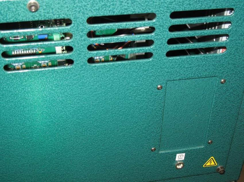
Carpenter Model 36B Compu-Cut®

                     Safety and Pneumatic Notices

            CAUTION
This equipment comes equipped with a LEXAN safety
guard, which contains a safety interlock switch. The
machine will not operate unless the guard is installed and
in the closed position on the Model 36B.

                 **IMPORTANT**
Do not attempt to defeat the function or purpose of the
safety interlock switch. Serious injury to the operator’s
eyes, fingers or other body parts may result from attempts
to operate this equipment with the safety guard in the
raised position.
This machine contains pneumatic components. It is
extremely important that this machine is connected to a
clean, filtered, and lubricated air supply.

Contaminated air may cause the machine to malfunction.
Failure to follow these installation instructions may result
in damage to the machine that will not be covered under
warranty. Please refer to page 27 of this manual for
specifications regarding the use of an automatic, inline
oiler.
   Carpenter Model 36B Compu-Cut® • Phone: (315) 682-9176 • Fax: (315) 682-9160
          Website: www.carpentermfg.com • Email: wire@carpentermfg.com

Revised 03/10/2021                                                         Page 6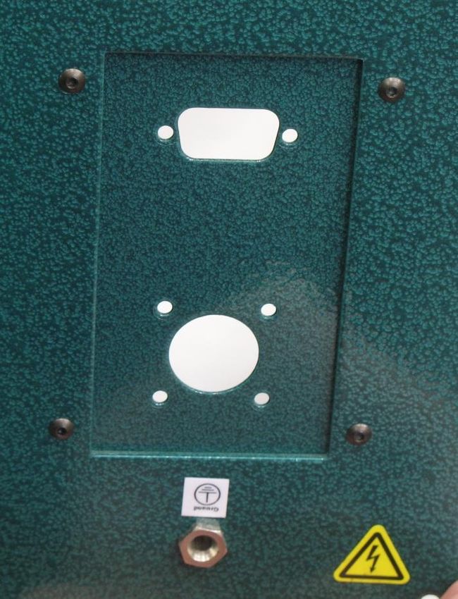
Carpenter Model 36B Compu-Cut®

                   Applications and Machine Specifications
    Applications

    With interchangeable cutting assemblies, the Model 36B is designed to measure and
    cut to length a number of different materials, including small solid wire; stranded wire;
    multi-conductor cable; rigid or flexible plastic tubing; flat cable; sleeving; and braid.

    Note: A motorized prefeed (Carpenter Model 56A, Model 57, Model 58D, or Model 59)
    may be necessary to assist the Model 36B, depending on application.

    Machine Specifications

Electrical Connection                  88 – 264 VAC, 47 – 63 Hz self-adjusting
Air Supply                             80 – 100 PSI (5.5 – 6.9 BAR) **CLEAN, FILTERED, AND
                                       LUBRICATED AIR ONLY**
Main Fuses                             2 – 5 x 20mm 6.3 AMP fast-action
Maximum Round Material Diameter        1.000” (25.4mm) [material dependent]
Maximum Flat Material Width            1.000” (25.4mm) [material dependent]
Cut Length                             0.05” – 9,999.99” (1.2 – 99,999.9mm) [longer lengths
                                       obtainable in inches]
Quantity                               1 – 999,999 pieces
Unit of Measure                        Inches or mm, user-selectable
Transport Speeds                       5 programmable
Single Program Memory                  500 programs
Kitting Program Memory                 100 programs
Password Protection                    User-programmable
Dimensions                             13.7” (W) X 11” (H) X 17” (D)
                                       (348mm [W] X 279mm [H] X 432mm [D])
Weight                                 52 lbs. (24 kg)

         Carpenter Model 36B Compu-Cut® • Phone: (315) 682-9176 • Fax: (315) 682-9160
                Website: www.carpentermfg.com • Email: wire@carpentermfg.com

    Revised 03/10/2021                                                                  Page 7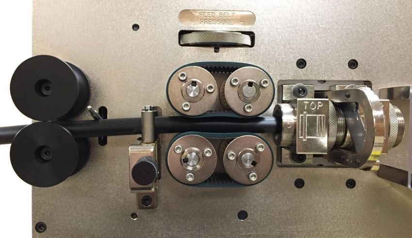
Carpenter Model 36B Compu-Cut®

                     Section 1 – Initial Machine Setup
Follow the steps below to set up the Model 36B:

   1. Insert air tubing into the straight connector, located on the back panel of the
      machine; connect the opposite end to the air supply. Make certain the air supply
      is clean and filtered with an attached automatic, inline oiler (refer to page 27 for
      specifications). The absence of an inline oiler may result in failure of the
      pneumatic cylinder that operates the blade mechanism.

   2. Plug the female end of the power cord into the power entry module, located on
      the left side of the machine. Plug the male end of the power cord into a proper
      electrical outlet.

   3. Turn on the power switch.

Input and Output Guide Selection

The Model 36B comes installed with (1) PN 6617 input guide, and (1) PN 6620 output
guide of the customer’s choice. Eight input and output guide sizes are available; sizes
range from 1/8” to 1.000”, in 1/8” increments. Select the wire guide with the smallest
inside diameter that slips freely over the outside diameter of the material to be
processed.

Input and Output Guide Change

Follow the steps below to change the input and output guides on the Model 36B:

   1. Press the WIRE GUIDE button. This will pull the blade in toward the machine
      and into position for the guide change.

   2. Remove (2) PN 6615 guide blocks by loosening and removing (4) PN 2923
      screws and (4) PN 6510 washers.

   3. Remove each guide by unscrewing PN 6619 guide retaining rings.

   4. To reinstall, insert each guide into each PN 6615 guide block, until the shoulder
      of the guide settles into the guide block. Secure each guide into place with the
      guide retaining rings.

   5. Important: Refer to Figure 1 and Figure 2 below for proper positioning when
      reinstalling the PN 6615 guide blocks. Push each guide block up to the blade
      and secure into place with the (4) PN 6510 washers and (4) PN 2923 screws.

   Carpenter Model 36B Compu-Cut® • Phone: (315) 682-9176 • Fax: (315) 682-9160
          Website: www.carpentermfg.com • Email: wire@carpentermfg.com

Revised 03/10/2021                                                                 Page 8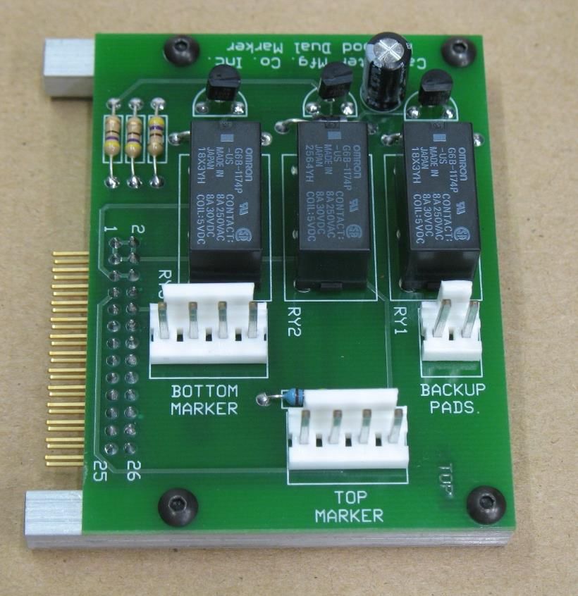
Carpenter Model 36B Compu-Cut®

                             Figure 1: Model 36B Guide Setup (1)

                             Figure 2: Model 36B Guide Setup (2)

Loading Material

Follow the steps below to load material into the Model 36B:

   1. Place material underneath the out of material rod.

   2. Feed material through the centering roller guides and adjust the rollers to center
      the material into the entrance of the feed belts.

   3. Select the LOAD key and keep it pressed down until the material has been fed
      completely through the machine.

   4. Once the material exits the machine, release the switch.
   Carpenter Model 36B Compu-Cut® • Phone: (315) 682-9176 • Fax: (315) 682-9160
          Website: www.carpentermfg.com • Email: wire@carpentermfg.com

Revised 03/10/2021                                                                Page 9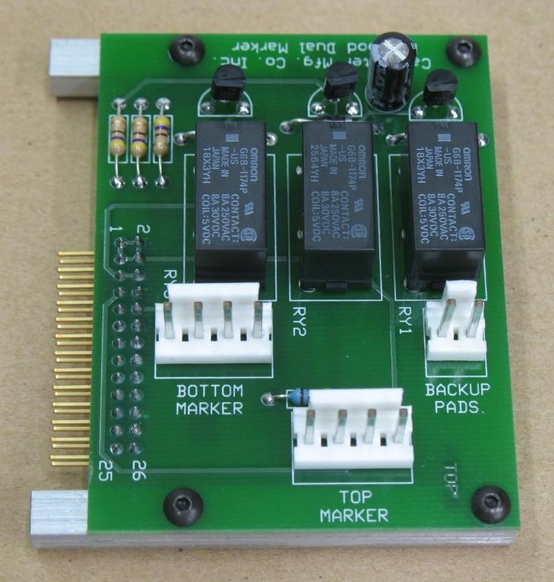
Carpenter Model 36B Compu-Cut®

Feed Belt Pressure

Turn the PN 8449 feed belt pressure adjustment knob clockwise (+) to apply belt
pressure, or counter-clockwise (-) to release belt pressure. Do not apply excessive belt
pressure. Belts only need to be snug to the material.

 PN 8563 Out of Material Rod                                           PN 8449 Feed Belt Pressure
                                                                            Adjustment Knob
                                  PN 8481 Centering Rollers

                                  Figure 3: Machine Ready for Processing

   PN 8476 Input Centering Knob              PN 6617 (Sizes 1 – 8) Input Guide    PN 6620 (Sizes 1 – 8) Output Guide

   Carpenter Model 36B Compu-Cut® • Phone: (315) 682-9176 • Fax: (315) 682-9160
          Website: www.carpentermfg.com • Email: wire@carpentermfg.com

Revised 03/10/2021                                                                                  Page 10
Carpenter Model 36B Compu-Cut®
Section 2 – The LCD Display
LCD Display Examples
The Model 36B utilizes an easy-to-use keypad and an LCD display. Below are several
examples of labeled sample displays.
Unit of Measure – MM Shown
Cut Amount
Cut Length (mm shown) Batching Activated
Feed Speed
Wire Stacker Activated Unit of Measure (mm shown) Wire Marker Activated
Unit of Measure – Inches Shown
Cut Length (inches shown) Cut Amount
Program Number
Unit of Measure (inches shown)
Carpenter Model 36B Compu-Cut® • Phone: (315) 682-9176 • Fax: (315) 682-9160
Website: www.carpentermfg.com • Email: wire@carpentermfg.com
Revised 03/10/2021 Page 11Carpenter Model 36B Compu-Cut®
Kitting Display
Cut Length (current member) Current Member Number Cut Amount (Current Member)
Feed Speed
Program Number Kit Quantity (this
Kit Number (Current Member) number will count down
during processing)
Cut length, member amount, and program number values relate to current member
number being processed. These values will change as each member of the kit is being
processed. Kitting is highlighted in detail beginning on page 16.
Carpenter Model 36B Compu-Cut® • Phone: (315) 682-9176 • Fax: (315) 682-9160
Website: www.carpentermfg.com • Email: wire@carpentermfg.com
Revised 03/10/2021 Page 12Carpenter Model 36B Compu-Cut®
Section 3 – Programming
**IMPORTANT NOTE**
DO NOT USE SHARP OBJECTS ON KEYPAD. FINGERTIP PRESSURE IS
SUFFICIENT.
There are several possible step-by-step combinations to set the machine up for
programming. The following step-by-step procedure is meant to be used as a guide
and is just one of the many ways the machine may be programmed to process wire.
1. Power the machine on and press ENTER.
2. Press the UNITS button. The Model 36B may be programmed in either inches or
millimeters. Press CLEAR to toggle between inches and millimeters and press
ENTER. (For Model 36, Model 36A, and Model 36B machines with a software
version prior to 2.08, navigate to Section 4 – Special Features, and follow the
Unit of Measure instructions on page 18).
3. Press the LENGTH button. This value is the length of processed pieces. Using
the numerical keypad, input the length dimension and press ENTER.
4. Press the AMOUNT button. This value is the number of pieces to be processed,
and also allows access to multiple batch processing mode. Using the numerical
keypad, input the number of pieces to be processed and press ENTER.
a. The batch feature allows the operator to process required pieces in a
single batch or multiple batches. The machine will default to one batch.
To accept this value press ENTER. To process total amount in multiple
batches, using the numerical keypad, input the number of batches to
process (up to 999) and press ENTER.
b. If a number greater than one was entered in the latter step, using the
numerical keypad, input the amount of pieces to process per batch and
press ENTER. (The batching mode will override the original amount
entered. Therefore, the number of pieces per batch times the number of
batches does not need to total the original amount entered).
5. Press the FEED SPEED button. This value determines the speed of the material
passing through the machine. Using the numerical keypad, select a feed speed
and press ENTER.
a. 1: slow
2: slow/medium
3: medium
Carpenter Model 36B Compu-Cut® • Phone: (315) 682-9176 • Fax: (315) 682-9160
Website: www.carpentermfg.com • Email: wire@carpentermfg.com
Revised 03/10/2021 Page 13Carpenter Model 36B Compu-Cut®
4: medium/fast
5: fast
The Model 36B is now programmed to measure and cut material to length. The
operator is now ready to run a sample piece and check for initial setup quality.
Continue with the following procedures to assist in processing a sample.
Single Cycle
Select the SINGLE CYCLE button to produce a sample piece to check for accuracy.
This feature will cut off the end that is protruding through the blades from the setup and
then measure and cut a single piece. If corrections are necessary, proceed to length
correction for adjustments.
Length Correction
The Model 36B has a length correct feature which allows the operator to make
adjustments from the pre-programmed length versus the actual sample length. Small
variations are normal due to differences in material, tension, friction, wire diameter, etc.
If the sample piece was not the correct length, press the LENGTH CORRECT button to
make adjustments.
1. Measure the length of the produced sample piece. Using the numerical keypad,
input this value and press ENTER. The Model 36B will automatically calculate
the necessary correction. The next sample should be the exact programmed
length.
a. The possible range of correction is +/- 10% of the overall material length.
If a value outside of this range is entered an error message will appear.
The length correct value may be changed multiple times but typically a
single entry is all that is required if the sample piece was measured
accurately and the data was entered correctly.
Run Program
After a satisfactory sample piece is produced and all settings are correct, press RUN.
This will process the current program.
Stop Program
If at any time the operator must stop processing, press STOP.
Unloading Material
Carpenter Model 36B Compu-Cut® • Phone: (315) 682-9176 • Fax: (315) 682-9160
Website: www.carpentermfg.com • Email: wire@carpentermfg.com
Revised 03/10/2021 Page 14Carpenter Model 36B Compu-Cut®
Unload material by pressing the UNLOAD button. Material will automatically feed
backward through the machine as long as the button is depressed.
Storing Programs
The Model 36B will store up to 500 programs. The operator may access this function by
pressing the MEMORY button.
1. To store a program, press the MEMORY button and press 1 on the numerical
keypad. Using the numerical keypad, input up to any three-digit program number
and press ENTER. The Model 36B will display program number and confirm that
it was stored; press ENTER.
a. If the operator enters a number already stored in the Model 36B, the LCD
display will ask the operator to press 1 to overwrite or press CLEAR.
Input 1 to overwrite the previously stored program, or press CLEAR to
keep the previously stored program; press ENTER.
Recalling Programs
1. To recall a program, press the MEMORY button, press 2 on the numerical
keypad, then press 1 on the numerical keypad. Input the stored three-digit
program number and press ENTER.
a. When recalling a program from memory, the value for belt pressure is not
stored. The operator must always readjust the belt pressure to the
process material. If incorrect belt pressure is used, excessive belt wear
may occur. If the operator experiences a problem, stored value may need
to be changed.
Carpenter Model 36B Compu-Cut® • Phone: (315) 682-9176 • Fax: (315) 682-9160
Website: www.carpentermfg.com • Email: wire@carpentermfg.com
Revised 03/10/2021 Page 15Carpenter Model 36B Compu-Cut®
Section 4 – Special Features
To access the Model 36B special features, press the MENU button. Continue to press
the MENU button to scroll through the options. To select a feature press ENTER and
follow appropriate instructions.
Kitting
The Model 36B is equipped with a kitting feature. This feature allows the operator to
create a kit of different lengths of the same material. A kit may contain up to twenty
different items, or what are also referred to as members. Each member may be one of
500 previously stored programs. A maximum of 100 kit programs may be stored in the
machine’s memory and recalled at any time. Before programming a kit, the operator
must have determined the following:
• Which previously stored programs will be processed;
• The amount of pieces to process for each selected program;
• The number of kits to process;
• Which setting (auto or manual) is preferred at the end of each kit.
1. After selecting the kitting option, the CLEAR button will toggle between ON/OFF.
To turn kitting on, press CLEAR, then press ENTER.
2. A member is each number within the kit. The software will assign each member
number as the operator enters the kit information. Input the program number of
the first member of the kit and press ENTER.
3. Input the amount for the first member of the kit and press ENTER.
4. The Model 36B will repeat steps 1 and 2 above for each member of the kit.
When all of the kit members are entered, input program number “000” to end the
sequence.
5. Input the number of kits to run and press ENTER.
6. Press CLEAR to toggle between manual pause mode or auto pause mode and
press ENTER.
a. Manual pause mode will stop the machine at the end of each kit and
require the operator to press ENTER to proceed to the next kit.
i. Begin processing by pressing RUN.
Carpenter Model 36B Compu-Cut® • Phone: (315) 682-9176 • Fax: (315) 682-9160
Website: www.carpentermfg.com • Email: wire@carpentermfg.com
Revised 03/10/2021 Page 16Carpenter Model 36B Compu-Cut®
1. To run the next kit, press ENTER, or press CLEAR to quit.
The machine will return to the run screen if CLEAR is
pressed.
a. After pressing CLEAR, to continue with the current kit
program, press RUN, or reprogram the machine for a
different operation.
2. The operator may stop the processing sequence at any
moment by pressing STOP, and may restart by pressing
RUN.
b. Auto pause mode will set a time delay between kits to allow the operator
to gather the pieces before the next kit starts.
i. Input the pause time between kits and press ENTER.
ii. Begin processing by pressing RUN.
1. The machine will pause for the programmed time and then
proceed to the next kit.
2. The operator may stop the processing sequence at any
moment by pressing STOP, and may restart by pressing
RUN.
Storing Kitting Programs
The Model 36B will store up to 100 kitting programs. To store a kitting program, press
the MEMORY button.
1. To store a kit, press the MEMORY button and press 1 on the numerical keypad.
Input up to any three-digit kit number and press ENTER. The Model 36B will
display kit number and confirm that it was stored; press ENTER.
a. If the operator enters a number already stored in the Model 36B, the LCD
display will ask the operator to press 1 to overwrite or press CLEAR.
Input 1 to overwrite the previously stored kit, or press CLEAR to keep the
previously stored kit; press ENTER.
Recalling Kitting Programs
1. To recall a kit, press the MEMORY button, press 2 on the numerical keypad, then
press 2. Input the three-digit stored kit number and press ENTER.
Carpenter Model 36B Compu-Cut® • Phone: (315) 682-9176 • Fax: (315) 682-9160
Website: www.carpentermfg.com • Email: wire@carpentermfg.com
Revised 03/10/2021 Page 17Carpenter Model 36B Compu-Cut®
a. When recalling a kit from memory, the value for belt pressure is not
stored. The operator must always readjust the belt pressure to the
process material. If incorrect belt pressure is used, excessive belt wear
may occur. If the operator experiences a problem, stored value may need
to be changed.
2. Input the number of kits to run and press ENTER.
3. Press RUN to begin processing kit(s).
Wire Marking
Factory-installed option. Refer to page 20 for program instructions after installation.
Unit of Measure
The Model 36B may be programmed in either inches or millimeters. Press CLEAR to
toggle between inches and millimeters and press ENTER. (For Model 36B machines
with software version 2.08 or later, this option will not appear on the machine menu.
Instead, press the UNITS button. Press CLEAR to toggle between inches and
millimeters and press ENTER).
Turn Password On/Off
The Model 36B is equipped with a password feature. When the password is activated,
the ability to change program data is prohibited. Press CLEAR to toggle between
password on and password off and press ENTER.
1. If this option is turned on for the first time, the LCD display will prompt the
operator to enter old password. Input the factory-set password, “123”, and press
ENTER.
a. Input the desired password number, up to six digits, and press ENTER.
Store New Password
This option will allow the operator to change the password at their discretion.
1. Input old password and press ENTER.
2. Input the desired password number, up to six digits, and press ENTER.
Wire Stacker
Carpenter Model 36B Compu-Cut® • Phone: (315) 682-9176 • Fax: (315) 682-9160
Website: www.carpentermfg.com • Email: wire@carpentermfg.com
Revised 03/10/2021 Page 18Carpenter Model 36B Compu-Cut®
Factory-installed option. Refer to page 22 for installation and programming instructions.
Wire Coiler
The Model 36B will interface with Carpenter’s Model 84 Material Coiling Unit. Refer to
page 22 for installation and programming instructions.
Wire Sensor On/Off
The Model 36B is equipped with an out of material sensor. It may be necessary to turn
the sensor off when processing light gauge/weight material that may not support the out
of material rod. If the sensor is activated, the Model 36B will automatically stop
processing when it runs out of material. If the sensor is not activated, the machine will
continue to run and finish the current program until the programmed amount reaches
zero. Press CLEAR to toggle between wire sensor on and wire sensor off and press
ENTER.
Representatives Only
This submenu is to be accessed only by trained Carpenter Mfg. Co., Inc. sales
representatives.
Reserved
This submenu is to be accessed only by Carpenter Mfg. Co., Inc. staff.
Carpenter Model 36B Compu-Cut® • Phone: (315) 682-9176 • Fax: (315) 682-9160
Website: www.carpentermfg.com • Email: wire@carpentermfg.com
Revised 03/10/2021 Page 19Carpenter Model 36B Compu-Cut®
Section 5 – Accessory Control
Wire Marker
The Model 36B is capable of interfacing with various manufacturers of hot stamp wire
marking units. It is important to read the specific hot stamp wire marking unit operating
instructions before proceeding.
To activate the interface between the Model 36B and wire marker, install the exterior
cable between both units. The plug receptacle on the Model 36B is located on the back
of the machine cabinet. To access the wire marking option within the machine, press
the MENU button to toggle through the options and press ENTER when wire marking is
shown. Press CLEAR to toggle between wire marker on and wire marker off and press
ENTER.
When the wire marker option is activated, “MRK” will appear on the right side of the
LCD display.
All dimensions entered during setup will correspond with the unit of measure that is
programmed into the machine.
1. Refer to the specific hot stamp wire marking unit operating instructions for
suggested settings.
2. Input a dwell time and press ENTER.
3. With a tape measure or similar tool, measure the distance from the center of the
marking disc to the center of the blade on the Model 36B (marker offset). Input
this measurement and press ENTER.
4. The lead end mark distance is the distance from the leading end (right end) of
the wire to the center of the mark on the wire. Input this measurement and press
ENTER. The maximum distance is (wire length/2).
5. The trail end mark distance is the distance from the trailing end (left end) of the
wire to the center of the mark on the wire. Input this measurement and press
ENTER. The maximum distance is ((wire length/2) – 0.20).
6. The Model 36B wire marker interface allows the operator to program continuous
marking along the wire. To choose this option, input the distance between each
marking along the wire. Minimum distance is 0.50” or 0.00”. Input “0” to bypass
this option. Input the desired value and press ENTER.
Carpenter Model 36B Compu-Cut® • Phone: (315) 682-9176 • Fax: (315) 682-9160
Website: www.carpentermfg.com • Email: wire@carpentermfg.com
Revised 03/10/2021 Page 20Carpenter Model 36B Compu-Cut®
7. Press either the RUN or SINGLE CYCLE button to activate the marker setup
cycle. At this point, the Model 36B and the interfaced wire marker will go into a
setup cycle. The two units are now automatically synchronized to apply the
marks in the locations along the wire as previously programmed.
8. Process a few sample pieces. Measure the location of the center of the leading
end mark from the leading end of the wire. If the measured dimension is not
equal to the programmed lead end mark dimension, proceed to lead end mark
distance correction.
a. Before making any lead end mark corrections, be certain the overall length
is correct. Refer to the Length Correction section for more information.
b. The measured lead mark screen will not display until after a sample piece
is run using the RUN or SINGLE CYCLE button. To access this screen,
press the MENU button to toggle through the options and press ENTER
when wire marking is shown.
c. Scroll through the wire marking options pressing the ENTER button until
the measured lead mark option is displayed. Carefully measure from the
leading end of the cut wire to the center of the mark. If the measured
dimension is different than the programmed leading end mark distance,
proceed to the instructions below.
i. Measure from the lead end of the cut wire to the center of the lead
end mark. Input this measured dimension and press ENTER.
ii. Press either the RUN or SINGLE CYCLE button to activate the
market initialization cycle. When this cycle is complete, the marks
will have been shifted to their correct locations and normal
processing may begin.
d. A marker correction value may only be entered once. If, after running a
second test piece, the entered marker correction value is incorrect, the
operator must clear the previously entered correction value. To clear this
value, run the procedure below.
i. Press the MENU button to toggle through the options and press
ENTER when wire marking is shown. Scroll through the wire
marking options pressing the ENTER button until the measured
lead mark option is displayed. Press CLEAR, and then press
ENTER. This will reset the correction value back to its original
setting.
Carpenter Model 36B Compu-Cut® • Phone: (315) 682-9176 • Fax: (315) 682-9160
Website: www.carpentermfg.com • Email: wire@carpentermfg.com
Revised 03/10/2021 Page 21Carpenter Model 36B Compu-Cut®
ii. Press the SINGLE CYCLE button. This will produce a test piece
using the original programmed settings. On this test piece,
measure the distance from the lead end to the center of the lead
end mark. Input this measured dimension and press ENTER.
iii. Press either the RUN or SINGLE CYCLE button to activate the
market initialization cycle. When this cycle is complete, the marks
will have been shifted to their correct locations and normal
processing may begin.
Wire Stacker
The Model 36B offers the capability to interface with a wire stacker to collect longer wire
lengths. The electrical interface necessary to interface with a wire stacker must be
purchased separately and installed at the factory. It is important to read the specific
wire stacker operating instructions before proceeding.
To activate the interface between the Model 36B and wire stacker, install the exterior
cable between both units. The plug receptacle on the Model 36B is located on the back
of the machine cabinet. To access the wire stacker option within the machine, press the
MENU button to toggle through the options and press ENTER when wire stacker is
shown. Press CLEAR to toggle between wire stacker on and wire stacker off and press
ENTER.
When the wire stacker option is activated, a small square will appear on the left side of
the LCD display.
All dimensions entered during setup will correspond with the unit of measure that is
programmed into the machine.
1. Press CLEAR to toggle wire stacker on and press ENTER.
2. Enter the stacker dwell time. This time is determined by how long it takes the
stacker to complete its cycle for the current wire being processed.
Wire Coiler
The Model 36B will interface with Carpenter’s Model 84 Material Coiling Unit.
Note: The Model 36B must have appropriate software to interface with the Model 84.
Contact Carpenter Mfg. Co., Inc. for more details.
To interface the Model 36B with Carpenter’s Model 84 Material Coiling Unit, a PN
9580 external 9-pin “D” cable and a PN 9583 coiler accessory board kit must be
purchased from Carpenter Mfg. Co., Inc.
Carpenter Model 36B Compu-Cut® • Phone: (315) 682-9176 • Fax: (315) 682-9160
Website: www.carpentermfg.com • Email: wire@carpentermfg.com
Revised 03/10/2021 Page 22Carpenter Model 36B Compu-Cut®
To access the wire coiler option within the machine, press the MENU button to toggle
through the options and press ENTER when wire coiler is shown. Press CLEAR to
toggle between wire coiler on and wire coiler off and press ENTER.
The interface between the Model 36B and the Model 84 may be controlled by a PN
9585 foot switch assembly. For specific foot switch assembly and general material
coiling unit operating instructions, please view the Model 84 operator’s manual.
Carpenter Model 36B Compu-Cut® • Phone: (315) 682-9176 • Fax: (315) 682-9160
Website: www.carpentermfg.com • Email: wire@carpentermfg.com
Revised 03/10/2021 Page 23Carpenter Model 36B Compu-Cut®
Section 6 – Maintenance Procedures
Feed Belt Change or Removal
To change or remove the feed belts, follow the instructions below.
1. Power off the Model 36B and unplug the power input cord. Disconnect the
machine from the air supply.
2. Using the PN 8449 feed belt pressure adjustment knob, separate the feed belt
pair.
3. Remove (12) PN 5451 screws, (12) PN 8525 washers, and (4) PN 8514 belt
guides.
4. Remove PN 6627 feed belt pair.
5. To install a new feed belt pair, reverse the above steps.
6. Plug the power cord back in, reconnect the machine to the air supply, close
safety guard, and power on the Model 36B.
PN 8449 Feed Belt Pressure
PN 5451 Screw, PN 8525 Washer (12 Each) Adjustment Knob
Figure 4: Machine Prior to Feed Belt Change
PN 8514 Belt Guide (4) PN 6627 Feed Belt (1 Pair)
Carpenter Model 36B Compu-Cut® • Phone: (315) 682-9176 • Fax: (315) 682-9160
Website: www.carpentermfg.com • Email: wire@carpentermfg.com
Revised 03/10/2021 Page 24Carpenter Model 36B Compu-Cut®
Blade Change
To change or remove the blade, follow the instructions below.
1. Power off the Model 36B and unplug the power cord. Disconnect the machine
from the air supply.
2. Remove (2) PN 2923 screws and (2) PN 6510 washers. Remove the PN 6615
guide block (output side), only.
3. Loosen PN 3798 screws on PN 6674 bottom blade holder assembly. Loosen
and remove PN 3798 screws from PN 6678 top blade holder assembly. Remove
top blade holder assembly.
4. Remove PN 6628 blade. CAUTION: BLADE EDGE IS SHARP.
5. Brush all components clean using a soft bristle brush.
6. Install new blade per the diagram shown in Figure 6. Set blade bottom edge
between bottom blade holder assembly and PN 6670 cutter arm assembly. Set
blade top edge between dowel pins.
7. Reinstall PN 6678 top blade holder assembly with PN 3798 screws.
8. Plug the power cord back in, reconnect the machine to the air supply, close
safety guard, and power on the Model 36B.
9. Press the GUIDE SETUP button to position the cutter arm assembly and blade
for guide block (output side) reinstallation.
10. Reinstall the guide block (output side), ensuring the output guide is pushed up to
the blade. Tighten into place with (2) PN 2923 screws and (2) PN 6510 washers.
11. Press ENTER to return to the main run screen. Blade change is complete.
Carpenter Model 36B Compu-Cut® • Phone: (315) 682-9176 • Fax: (315) 682-9160
Website: www.carpentermfg.com • Email: wire@carpentermfg.com
Revised 03/10/2021 Page 25Carpenter Model 36B Compu-Cut®
PN 6678 Top Blade Holder Assembly
PN 6615 Guide Block (Output)
(Includes 2 PN 3798 Screws)
PN 2923 Screw,
PN 6510 Washer (2
Each)
PN 6674 Bottom Blade
Holder Assembly
(Includes 2 PN 3798
Figure 5: Machine Prior to Blade Change
Screws)
PN 6670 Cutter Arm Assembly
Blade
PN 6678 Top Blade Holder
Assembly (Includes 2 PN
3798 Screws)
PN 6670 Cutter Arm
Assembly
Figure 6: Blade Change
PN 6674 Bottom Blade Holder Assembly
(Includes 2 PN 3798 Screws)
Carpenter Model 36B Compu-Cut® • Phone: (315) 682-9176 • Fax: (315) 682-9160
Website: www.carpentermfg.com • Email: wire@carpentermfg.com
Revised 03/10/2021 Page 26Carpenter Model 36B Compu-Cut®
Machine Lubrication
It is very important to lubricate the pneumatic cylinder that operates the blade
mechanism. Use of an automatic, inline oiler filled with standard pneumatic tool oil is
required. The automatic inline oiler should be set so that he Model 36B receives
approximately one drop of pneumatic tool oil every 10 – 12 minutes of continuous
cutting (80 PSI).
Operating the machine without an automatic inline oiler may result in damage to the
pneumatic cylinder and other machine components.
Carpenter Model 36B Compu-Cut® • Phone: (315) 682-9176 • Fax: (315) 682-9160
Website: www.carpentermfg.com • Email: wire@carpentermfg.com
Revised 03/10/2021 Page 27Carpenter Model 36B Compu-Cut®
Section 7 – Recommended Spare Parts
The below items are recommended spare parts for the Model 36B.
Quantity per Machine Carpenter Part Number Description
1 6627 Feed Belt Pair
1 6628 Blade Pack (5 pcs.)
Section 8 – Optional Accessories
The below items are optional accessories for the Model 36B.
Carpenter Part Number Description
3600 Sleeving Cutter Head Assembly
3600AB Air Blast Kit for Sleeving Cutter Head
Assembly
6551 Regulator/Filter/Oiler Assembly
6650 Complete Input/Output Guide Set
6665 Feed Roller Kit
8520 Wire Marker/Wire Stacker Interface
8524 Wire Marker Interface Cable
9580 External 9-Pin “D” Cable (Coiler)
9583 Coiler Accessory Board Kit
Sleeving Cutter Head Assembly
The Model 36B now has the additional capability of processing flat material.
Carpenter Mfg. Co., Inc. now offers a state-of-the-art sleeving cutter head assembly to
process flat material up to 1” in width. The new sleeving cutter head assembly and the
popular utility blade cutter assembly are interchangeable, allowing one Model 36B to
essentially perform the functions of two different machines.
***The PN 3600 Sleeving Cutter Head Assembly is interchangeable not only on the
current selling Model 36B, but also the previous selling Model 36A.***
Carpenter Model 36B Compu-Cut® • Phone: (315) 682-9176 • Fax: (315) 682-9160
Website: www.carpentermfg.com • Email: wire@carpentermfg.com
Revised 03/10/2021 Page 28Carpenter Model 36B Compu-Cut®
Removing Utility Blade Cutter Arm Assembly
Figure 7: Utility Blade Cutter Arm Assembly Removal, Step 1
Figure 8: Utility Blade Cutter Arm Assembly Removal, Step 2
Carpenter Model 36B Compu-Cut® • Phone: (315) 682-9176 • Fax: (315) 682-9160
Website: www.carpentermfg.com • Email: wire@carpentermfg.com
Revised 03/10/2021 Page 29Carpenter Model 36B Compu-Cut®
Installing Sleeving Cutter Head Assembly
Figure 9: PN 3600 Sleeving Cutter Head Assembly Installation, Step 1
Figure 10: PN 3600 Sleeving Cutter Head Assembly Installation, Step 2
Carpenter Model 36B Compu-Cut® • Phone: (315) 682-9176 • Fax: (315) 682-9160
Website: www.carpentermfg.com • Email: wire@carpentermfg.com
Revised 03/10/2021 Page 30Carpenter Model 36B Compu-Cut®
Figure 11: PN 3600 Sleeving Cutter Head Assembly Installation, Step 3
Loading Material
With the PN 3600 Sleeving Cutter Head Assembly properly fastened to the machine,
material may now be processed. Follow the steps below to load material into the Model
36B:
1. Place material underneath the out of material rod.
2. Feed material through the centering roller guides and adjust the rollers to center
the material into the entrance of the feed belts.
3. Select the LOAD key and keep it pressed down until the material has been fed
completely through the machine.
4. Once the material exits the machine, release the switch.
5. Using the PN 6584 Sleeving Cutter Adjusting Knob, adjust the material guide
opening to the appropriate width for the material loaded into the machine. Refer
to Figure 12 below.
6. For programming instructions, refer to page 13.
Carpenter Model 36B Compu-Cut® • Phone: (315) 682-9176 • Fax: (315) 682-9160
Website: www.carpentermfg.com • Email: wire@carpentermfg.com
Revised 03/10/2021 Page 31Carpenter Model 36B Compu-Cut®
Material Guide
Opening
PN 6584 Sleeving
Cutter Adjusting Knob
Figure 12: Adjusting Material Guide Opening, PN 3600 Sleeving Cutter Head Assembly
Blade Change
Figure 13: PN 3600 Sleeving Cutter Head Assembly Blade Change, Step 1
Carpenter Model 36B Compu-Cut® • Phone: (315) 682-9176 • Fax: (315) 682-9160
Website: www.carpentermfg.com • Email: wire@carpentermfg.com
Revised 03/10/2021 Page 32Carpenter Model 36B Compu-Cut®
Figure 14: PN 3600 Sleeving Cutter Head Assembly Blade Change, Step 2
Figure 15: PN 3600 Sleeving Cutter Head Assembly Blade Change, Step 3
Carpenter Model 36B Compu-Cut® • Phone: (315) 682-9176 • Fax: (315) 682-9160
Website: www.carpentermfg.com • Email: wire@carpentermfg.com
Revised 03/10/2021 Page 33Carpenter Model 36B Compu-Cut®
Figure 16: PN 3600 Sleeving Cutter Head Assembly Blade Change, Step 4
Figure 17: PN 3600 Sleeving Cutter Head Assembly Blade Change, Step 5
Reverse the above process for blade reassembly. Apply light grease to blade surface
before assembly. Do not over-tighten cams.
Air Blast Kit for Sleeving Cutter Head Assembly
An optional air blast kit is offered for the PN 3600 Sleeving Cutter Head Assembly. The
air blast kit may be used on either a machine that does not have a modified guard or on
a machine that does have a modified guard. Figure 18 and Figure 19 below show the
correct routing instructions for the air blast kit.
Carpenter Model 36B Compu-Cut® • Phone: (315) 682-9176 • Fax: (315) 682-9160
Website: www.carpentermfg.com • Email: wire@carpentermfg.com
Revised 03/10/2021 Page 34Carpenter Model 36B Compu-Cut®
Figure 18: PN 3600AB Sleeving Cutter Head Assembly Air Blast Kit, with Guard Modification
Carpenter Model 36B Compu-Cut® • Phone: (315) 682-9176 • Fax: (315) 682-9160
Website: www.carpentermfg.com • Email: wire@carpentermfg.com
Revised 03/10/2021 Page 35Carpenter Model 36B Compu-Cut®
Figure 19: PN 3600AB Sleeving Cutter Head Assembly Air Blast Kit, without Guard Modification
Carpenter Model 36B Compu-Cut® • Phone: (315) 682-9176 • Fax: (315) 682-9160
Website: www.carpentermfg.com • Email: wire@carpentermfg.com
Revised 03/10/2021 Page 36Carpenter Model 36B Compu-Cut®
Coiler Accessory Board Kit and External Cable
The Model 36B may be equipped with a coiler accessory board kit to work in
conjunction with Carpenter’s Model 84 Material Coiling Unit. To interface the Model
36B with the Model 84, a coiler accessory board kit must be purchased from Carpenter
Mfg. Co., Inc. The coiler accessory board kit is to be used only in conjunction with
Carpenter’s Model 84.
If the coiler accessory board kit is not installed at the factory, follow the steps below to
correctly install the coiler accessory board kit.
1. Remove the (8) PN 3948 cap screws (and washers) from the Model 36B back
cover and remove the cover.
2. Remove the (4) PN 2849 button head screws and (4) PN 3812 hex nuts that hold
the PN 8953 jack cover onto the machine back cover. Refer to Figure 20 below.
PN 2849 Button Head
Screw (4)
PN 8953 Jack Cover
Figure 20: PN 8953 Jack Cover Before Rotating
3. After removing the button head screws and hex nuts, rotate the PN 8953 jack
cover so that the pre-cut holes are positioned in the opening of machine back
cover. Using the button head screws and hex nuts, reinstall the PN 8953 jack
cover to the machine back cover. Refer to Figure 21 below.
Carpenter Model 36B Compu-Cut® • Phone: (315) 682-9176 • Fax: (315) 682-9160
Website: www.carpentermfg.com • Email: wire@carpentermfg.com
Revised 03/10/2021 Page 37Carpenter Model 36B Compu-Cut®
Figure 21: PN 8953 Jack Cover After Rotating
4. Locate and remove the contents of the PN 9583 coiler accessory board kit.
5. Install the PN 8928 internal marker/foot switch cable to the PN 8953 jack cover
using the included (4) PN 2849 button head screws and (4) PN 3812 hex nuts.
6. Install the PN 9584 internal 9-pin “D” input cable to the PN 8953 jack cover using
the hardware included with this cable. Refer to Figure 22 below.
Carpenter Model 36B Compu-Cut® • Phone: (315) 682-9176 • Fax: (315) 682-9160
Website: www.carpentermfg.com • Email: wire@carpentermfg.com
Revised 03/10/2021 Page 38Carpenter Model 36B Compu-Cut®
PN 9584 Internal 9-Pin “D”
Input Cable (Installed)
PN 8928 Internal
Marker/Foot Switch
Cable (Installed)
Figure 22: PN 8928 and PN 9584 Cables Installed to PN 8953 Jack Cover
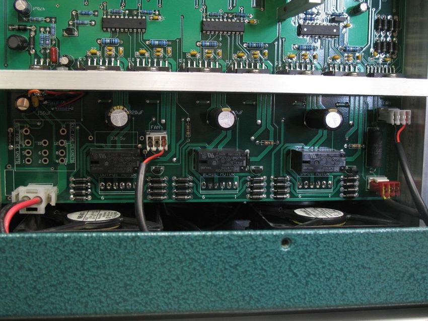
7. Remove the (4) PN 2412 cap screws securing the main printed circuit (PC) board
to the bottom of the Model 36B cabinet.
8. Unplug the (4) connectors located at the bottom of the PC board. Refer to Figure
23 below.
Carpenter Model 36B Compu-Cut® • Phone: (315) 682-9176 • Fax: (315) 682-9160
Website: www.carpentermfg.com • Email: wire@carpentermfg.com
Revised 03/10/2021 Page 39Carpenter Model 36B Compu-Cut®
PC Board
Connectors (4)
Figure 23: PC Board Connectors
9. Locate the marker/expansion connector on the PC board. Refer to Figure 24
below.
PC Board
Marker/Expansion
Connector
Figure 24: PC Board Marker/Expansion Connector
Carpenter Model 36B Compu-Cut® • Phone: (315) 682-9176 • Fax: (315) 682-9160
Website: www.carpentermfg.com • Email: wire@carpentermfg.com
Revised 03/10/2021 Page 40Carpenter Model 36B Compu-Cut®
10. Carefully line up the pins located on the PN 8958 dual marker/coiler board to the
marker/expansion connector located on the PC board. Plug the PN 8958 dual
marker/coiler board pins into the marker/expansion connector until the mounting
rails of the PN 8958 dual marker/coiler board are seated onto the PC board.
Refer to Figure 25 below.
PN 8958 Dual
Marker/Coiler
Board Pins
PN 8958 Dual
Marker/Coiler Board
Figure 25: PN 8958 Dual Marker/Coiler Board
Note: The connector corner pin numbers (1, 2, 25, and 26) are marked on both
boards. Line up Pin 1 and Pin 2 of the PN 8958 dual marker/coiler board with
Pin 1 and Pin 2 of the marker/expansion connector on the PC board.
11. Carefully lift the PC board and rotate the bottom of the board so that the back of
the marker/expansion connector may be accessed.
12. Install (2) PN 3811 cap screws into each mounting rail of the PN 8958 dual
marker/coiler board and secure. Refer to Figure 26 below.
Carpenter Model 36B Compu-Cut® • Phone: (315) 682-9176 • Fax: (315) 682-9160
Website: www.carpentermfg.com • Email: wire@carpentermfg.com
Revised 03/10/2021 Page 41Carpenter Model 36B Compu-Cut®
Location for (2) PN
3811 Cap Screws
Figure 26: Installing (2) PN 3811 Cap Screws into PN 8958 Dual Marker/Coiler Board Mounting Rails
13. Carefully rotate the bottom of the PC board back into the machine cabinet and
secure using the (4) PN 2412 cap screws removed in Step 7 above.
14. Reinstall the (4) connectors removed in Step 8 above.
15. Plug in the 4-pin connector from the PN 8928 internal marker/foot switch cable
on the back of the PN 8953 jack cover to the connector on the PN 8958 dual
marker/coiler board labeled “bottom marker.”
16. Plug in the 4-pin connector from the PN 9584 internal 9-pin “D” input cable on the
back of the PN 8953 jack cover to the connector on the PN 8958 dual
marker/coiler board labeled “top marker.” Plug in the remaining 2-pin connector
to the connector on the PN 8958 dual marker/coiler board labeled “backup pads.”
Refer to Figure 27 below.
Carpenter Model 36B Compu-Cut® • Phone: (315) 682-9176 • Fax: (315) 682-9160
Website: www.carpentermfg.com • Email: wire@carpentermfg.com
Revised 03/10/2021 Page 42Carpenter Model 36B Compu-Cut®
PN 9584 Internal 9-Pin
“D” Input Cable 2-Pin
PN 8928 Internal Connector Location
Marker/Foot Switch Cable
4-Pin Connector Location
PN 9584 Internal 9-Pin
“D” Input Cable 4-Pin
Connector Location
Figure 27: Cable Connector Locations
17. Reinstall the machine back cover using the PN 3948 cap screws (and washers)
removed in Step 1 above.
18. The PN 9580 external 9-pin “D” cable must be installed between the Model 36B
and the Model 84. Insert one 9-pin “D” end of the PN 9580 external 9-pin “D”
cable into the receptacle on the back of the Model 84. Refer to Figure 28 below.
Carpenter Model 36B Compu-Cut® • Phone: (315) 682-9176 • Fax: (315) 682-9160
Website: www.carpentermfg.com • Email: wire@carpentermfg.com
Revised 03/10/2021 Page 43Carpenter Model 36B Compu-Cut®
Figure 28: Inserting the 9-Pin “D” End of the PN 9580 External 9-Pin “D” Cable into the Model 84
Receptacle
19. Insert the other 9-pin “D” end of the PN 9580 external 9-pin “D” cable into the PN
9583 coiler accessory board kit previously installed on the back of the Model
36B. Refer to Figure 29 below.
Figure 29: Inserting a 9-Pin “D” End of the PN 9580 External 9-Pin “D” Cable into the PN 9583 Coiler
Accessory Board Kit
Carpenter Model 36B Compu-Cut® • Phone: (315) 682-9176 • Fax: (315) 682-9160
Website: www.carpentermfg.com • Email: wire@carpentermfg.com
Revised 03/10/2021 Page 44Carpenter Model 36B Compu-Cut®
Section 9 – Important Elements for Trouble-Free Operation
For trouble-free operation, follow the guidelines below.
1. The unit must be plugged into a proper electrical outlet, and the machine must be
turned on.
2. The air tubing must be properly connected to the air source and to the machine.
3. The feed belt pressures must be adjusted properly for the current application.
4. The correct input guide and output guide must be used for the current
application.
5. The data entered into the fields must be correct and accurate.
6. Use of a motorized prefeed may be required for certain applications.
Common Problem List of Checks
Blade Error 1. Check that material does not exceed machine cutting
limits
2. Check air pressure (current air pressure setting may
be too low)
3. Verify air tubing is properly attached
Common Problem List of Checks
Length Inaccuracies 1. Check feed speed
2. Check feed belt pressure
3. Verify wire length setting
4. A motorized prefeed may be required
5. Check input and output guide clearance
Common Problem List of Checks
Material Jams 1. Check input and output guide clearance
2. Check feed speed
3. Check feed belt pressure
4. Check for possible material splice
5. Check for presence of foreign material/debris
Common Problem List of Checks
Material Tracking 1. Check feed belt pressure
Incorrectly through
Feed Belts
Carpenter Model 36B Compu-Cut® • Phone: (315) 682-9176 • Fax: (315) 682-9160
Website: www.carpentermfg.com • Email: wire@carpentermfg.com
Revised 03/10/2021 Page 45You can also read