VictronConnect - VE.Bus Configuration guide - ENGLISH - Victron Energy
←
→
Page content transcription
If your browser does not render page correctly, please read the page content below
ENGLISH

VictronConnect - VE.Bus
  Configuration guide

                          rev 02 06/2021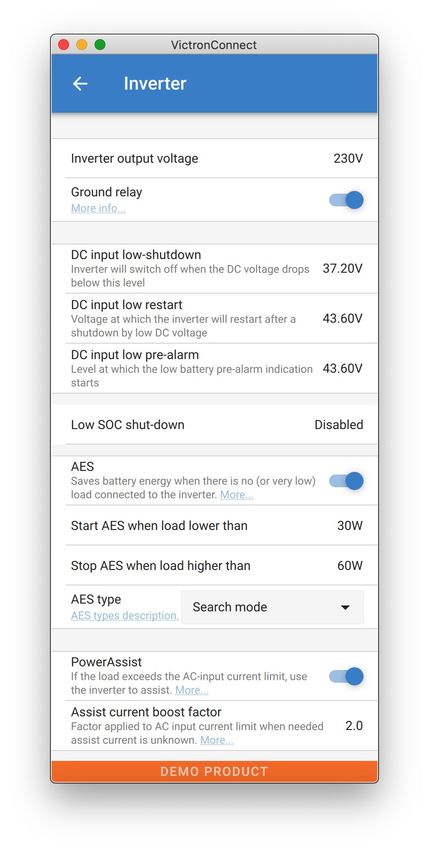
VictronConnect - VE.Bus Configuration guide

Table of Contents
  1. Warning ................................................................................................................................ 1

  2. Introduction ........................................................................................................................... 2

  3. Limitations ............................................................................................................................. 3
         3.1. VictronConnect vs VEConfigure & VEFlash .............................................................................. 3
         3.2. Required firmware versions ................................................................................................ 3
         3.3. VE.Bus Smart dongle limitations .......................................................................................... 3

  4. Overview Video ....................................................................................................................... 4

  5. Connecting ............................................................................................................................ 5

  6. Demo Mode Menu .................................................................................................................... 6

  7. Display Options ...................................................................................................................... 7

  8. Status Mode ........................................................................................................................... 8

  9. Settings Mode ......................................................................................................................... 9

  10. Description of Settings .......................................................................................................... 10
         10.1. General ....................................................................................................................    10
                10.1.1. System frequency setting .....................................................................................         10
                10.1.2. AC1 input current limit .........................................................................................      10
                10.1.3. Current limit overruled by remote ............................................................................         10
                10.1.4. Current limit overruled by remote ............................................................................         10
                10.1.5. Enable Battery Monitor ........................................................................................        10
                10.1.6. Battery capacity ................................................................................................      11
                10.1.7. State of charge when bulk finished ..........................................................................          11
                10.1.8. Charge efficiency ..............................................................................................       11
         10.2. Grid ........................................................................................................................   11
                10.2.1. Accept wide frequency range ................................................................................           11
                10.2.2. UPS Function ..................................................................................................        11
                10.2.3. AC Voltage Connection and Disconnection .................................................................              11
                10.2.4. Country / grid code standard .................................................................................         12
         10.3. Inverter ....................................................................................................................   12
                10.3.1. Inverter output voltage ........................................................................................       12
                10.3.2. Ground Relay ..................................................................................................        12
                10.3.3. DC input low-shutdown .......................................................................................          12
                10.3.4. DC input low restart ...........................................................................................       12
                10.3.5. DC input low pre-alarm ........................................................................................        13
                10.3.6. Low SOC shut-down ..........................................................................................           13
                10.3.7. AES ..............................................................................................................     13
                10.3.8. PowerAssist ....................................................................................................       13
                10.3.9. Assist current boost factor ....................................................................................       13
         10.4. Charger ...................................................................................................................     14
                10.4.1. Enable charger .................................................................................................       14
                10.4.2. Charge current .................................................................................................       14
                10.4.3. Float voltage ....................................................................................................     15
                10.4.4. Absorption voltage .............................................................................................       15
                10.4.5. Repeated absorption interval .................................................................................         15
                10.4.6. Repeated absorption time ....................................................................................          15
                10.4.7. Maximum absorption time ....................................................................................           15
                10.4.8. Charge curve ...................................................................................................       15
                10.4.9. BatterySafe .....................................................................................................      15
                10.4.10. Lithium battery mode ........................................................................................         15
                10.4.11. Storage mode .................................................................................................        16
                10.4.12. Use equalisation ..............................................................................................       16
                10.4.13. Weak AC input ................................................................................................        16
                10.4.14. Stop after excessive bulk ....................................................................................        16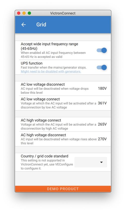
VictronConnect - VE.Bus Configuration guide

       10.5. AC Input Control .........................................................................................................    16
              10.5.1. When can the grid be controlled? ............................................................................        16
              10.5.2. Conditional AC input activation ...............................................................................      17
              10.5.3. Load Conditions ................................................................................................     17
              10.5.4. Battery Conditions .............................................................................................     18

11. Firmware Updates ................................................................................................................ 19
       11.1. When to do a firmware update ..........................................................................................       19
       11.2. Warning - reset to factory defaults .....................................................................................     19
       11.3. Procedure .................................................................................................................   19
       11.4. Firmware updates with multiple units (eg 3 phase) ..................................................................          21

12. Parallel, Three, Split-phase systems .......................................................................................... 22

13. Troubleshooting .................................................................................................................. 23
       13.1. I am having bluetooth connection issues ..............................................................................        23
               13.1.1. See if the MK3-USB works with a GX device. ..............................................................           23
       13.2. I am having Bluetooth connection issues .............................................................................         23
       13.3. VE.Bus firmware update fails at 5% on macOS ......................................................................            23
       13.4. I am having settings issues and would like to start again ...........................................................         23
       13.5. Still having issues? ......................................................................................................   23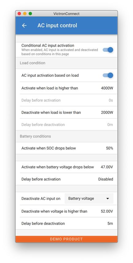
VictronConnect - VE.Bus Configuration guide

1. Warning

         The features described in this document are powerful tools. They are intended for use by Victron-trained
         Engineers, Installers and Dealers. Its usage must not be attempted by system Owners and Users.

         Configuring our Inverter/chargers, such as Multis and Quattros, requires both training and experience.

         Victron offers no direct support for un-trained individuals carrying-out configuration.

         Settings are protected by a password. This password is provided with Victron training. Please contact your
         Victron Distributor for further information.

Page 1                                                                                                              Warning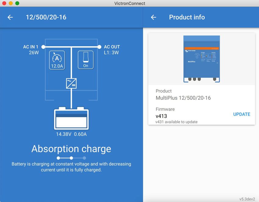
VictronConnect - VE.Bus Configuration guide

2. Introduction

The VE.Bus features of VictronConnect App allows you to configure, monitor, update and diagnose your VE.Bus Victron product.

VictronConnect connects to the inverters via a USB-MK3 accessory cable, or via the VE.Bus Smart Dongle (both sold separately).

The specific MK3 VE.Bus component is available for Android, Windows, and macOS X (but not iOS).

The specific VE.Bus Smart dongle component is available for Android, macOS X, iOS, (but not Windows).

VictronConnect is the perfect tool for installers to quickly and efficiently configure a system after wiring it. With VictronConnect, it's
safe, quick and easy to perform a firmware update of Victron products. No internet connection is required; and no files need to be
selected or downloaded. Just connect to the product.

System configuration is done with the MK3. Once configured, then the VE.Bus Smart dongle serves as an ideal entry level user
interface for a complete RV or Marine Victron system. Allowing monitoring, and operation of your device. Easily control the shore
power input current limit or switch on your inverter using the VictronConnect app.

The information available here applies to all Inverters and Inverter/chargers that have a VE.Bus communication port:

•   MultiPlus (including Compact)
•   MultiPlus-II
•   MultiPlus-II GX
•   MultiGrid
•   Quattros
•   EasySolar
•   EasySolar-II
•   EasySolar-II GX
•   Phoenix Inverters with a VE.Bus port

More general information about the VictonConnect App - how to install it; for example - can be found by referring to the overall
VictronConnect manual.

Page 2                                                                                                                      Introduction
VictronConnect - VE.Bus Configuration guide

3. Limitations

3.1. VictronConnect vs VEConfigure & VEFlash
VictronConnect is replacing VEConfigure and VEFlash. Its easier to use and works on more devices, not only on Windows.

The following features are not yet supported in VictronConnect. If you require this advanced functionality, you will still need to
use VEConfigure.

• Assistants (eg AC PV, ESS)
• Virtual Switch, though some of the most commonly used Virtual Switch functionality is available via the new AC input control
  feature [16].
• Changing the Grid Code
• Lithium Battery Wizard (for lithium battery types that require installation of an Assistant eg VE.Bus BMS)
• External Current Sensor - This is for use with the Multiplus-II external current sensor

3.2. Required firmware versions
Firmware version 200 is required to see data and make changes to settings.

To perform a firmware update, besides requiring firmware version 200, also the product needs to be equipped with a new type
microcontroller. Since at least five years, all inverter/chargers have been shipped with a new type microcontroller. This
microcontroller can be recognised by checking the 7 digit software number on a sticker on the device, it must start with 26 or 27.
For more information, see the VE.Bus firmware versions explained document. When above requirements are not met, use
VEFlash for firmware updating.

3.3. VE.Bus Smart dongle limitations
When connected over bluetooth, using the VE.Bus Smart Dongle, only status data, voltages, and other information can be read.
And it can be operated: switch between On, Off and Charger-only mode, and set a Shore current input limit. No changes can be
made to the product.

An MK3-USB is required to change settings and perform firmware updates and settings. And, as that requires a USB port, it is not
possible to change inverter/charger configuration or perform firmware updates on a Apple iPad or iPhone.

VictronConnect does not work with the MK2-USB.

Page 3                                                                                                                    Limitations
VictronConnect - VE.Bus Configuration guide

4. Overview Video

There is a video overview of this document, and it is intended to be used along side the more in-depth written documentation.

https://player.vimeo.com/video/373215592

Page 4                                                                                                          Overview Video
VictronConnect - VE.Bus Configuration guide

5. Connecting

Connecting the VE.Bus Inverter/Charger to your device requires an MK3-USB for configuration mode, or VE.Bus Smart
Dongle for status mode.

The MK3-USB or Smart dongle goes between the VE.Bus port on the inverter/charger, and either USB or Bluetooth connection
on your computer.

You will also need a straight RJ45 UTP cable. Also known as Ethernet patch or LAN cables. Use an industrially manufactured
cable. Handcrimped cables often give problems. Even in case a hand crimped cable works for a computer network, it might not
be of sufficient quality to work to connect Victron products.

Connecting with an Android device will require an additional OTG cable to convert the USB cable from the MK3-USB to the data
port on your device (typically micro-USB or USB-C).

This OTG adapter is not provided by Victron and will need to be sourced seperately.

To communicate, the Victron device must be supplied with the appropriate voltage.

     Product         Voltage Required
  Multi/Quattro      Either AC or DC
  Multi Compact      DC
  Inverters          DC

Once the connection is established, the program loads up the information from the connected unit.

Page 5                                                                                                           Connecting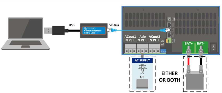
VictronConnect - VE.Bus Configuration guide

6. Demo Mode Menu

You can learn more about VictronConnect using the demo menu option. This option allows you to load a “demo” device which
simulates a real system. You can then adjust the settings/options. An in-app description in provded for some settings.

There is a choice of demo devices:

To access demo mode, select the three bar icon at the top left of the device list. Then Demo library.

Scroll through the options and then click or tap your selection.

It is possible to save the configuration you have made in demo mode, and load it into a real device.

Page 6                                                                                                   Demo Mode Menu
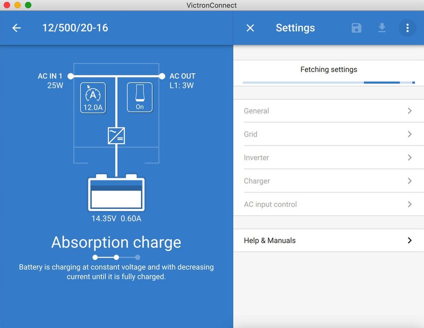
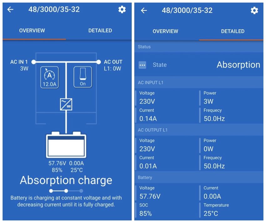
VictronConnect - VE.Bus Configuration guide

7. Display Options

There are two different modes available when connecting to a VE.Bus device with VictronConnect, Status & Settings

Page 7                                                                                                      Display Options
VictronConnect - VE.Bus Configuration guide

8. Status Mode

Status is available on Windows, macOS, Android and iOS operating systems.

You can access Status by either the MK3-USB or via Bluetooth with the VE.Bus Smart Dongle.

From the status window it is possible to switch the device On / Off / Charger Only from the switch button icon. It is also possible to
quickly adjust the AC input current limit (if the overruled by the remote panel setting is enabled).

For more information about this mode, and making the connection with the VE.Bus Smart Dongle, please watch this video:

https://player.vimeo.com/video/373231144

Page 8                                                                                                                  Status Mode
VictronConnect - VE.Bus Configuration guide

9. Settings Mode

You can only access Settings with a MK3-USB. You cannot use a VE.Bus Smart Dongle to access Settings Mode.

Settings is available on Windows, macOS and Android operating systems.

Settings on iPhone is not supported at this time, as iPhone does not support OTG connections from USB and is unable to
connect to the MK3-USB.

Page 9                                                                                                         Settings Mode
VictronConnect - VE.Bus Configuration guide

10. Description of Settings

10.1. General

10.1.1. System frequency setting
Alters the output frequency setting for the inverter.

10.1.2. AC1 input current limit
This setting is only active if no system panel is installed (is overruled by the remote panel if connected).

10.1.3. Current limit overruled by remote
If Overruled by remote is enabled, the input current limit can be set remotely by a GX Device or a Digital Multi Control. If not
enabled, it cannot be changed.

The use case is to typically leave it unchecked in stationary applications, as well as inputs connected to a generator, since for
them the input current limit is a static value and defined during installation.

For shore connections (boat and vehicle use) you check the box, so that the user of the system can change the input current limit
to match the shore connection they are currently using.

10.1.4. Current limit overruled by remote
Setting for use with ‘small’ generator - If an inverter-generator is used, such as the HONDA EU series, the shore current setting
will be dynamically reduced (following a period of low current consumption) to compensate for the engine reaction time when
higher loads are activated.

10.1.5. Enable Battery Monitor
Enabling the VE.Bus battery monitor, this also enables many features that can use a state of charge (SoC).

Page 10                                                                                                        Description of Settings
VictronConnect - VE.Bus Configuration guide

10.1.6. Battery capacity
In order for the battery monitor to be able to correctly calculate the "state of charge" the battery capacity of the connected
batteries must be known. Use this setting to specify the connected battery capacity in Ah.

10.1.7. State of charge when bulk finished
Use this setting to specify what the "state of charge" is set to when the Bulk phase is finished. This helps to calibrate "state of
charge" value due to inevitable measurement errors that accumulate over several charge/discharge cycles.

10.1.8. Charge efficiency
Setting the charge efficiency takes into account losses that occur when charging to improve the accuracy of the State of charge
reading. If you find the state of charge accuracy is drifting over time, try adjusting this setting.

10.2. Grid

10.2.1. Accept wide frequency range
Set the sensitivity of frequency measurement. This setting is used to indicate whether it is necessary for the input frequency to be
exactly 50 or 60 Hz. This is a setting that is primarily used in conjunction with generators (speed may not always be stable) to
prevent the Multi from rejecting the input supply.

10.2.2. UPS Function
Determines whether the Multi should be critical of the distortion in the supply waveform.

If UPS Function is deselected, this automatically activates the function preventing the lower voltage limit from being exceeded
with heavy start-up loads! (previously labeled ‘Allow inrush current’)

10.2.3. AC Voltage Connection and Disconnection
Voltage limits at which feedback relay opens/closes.

These are the limits at which the unit will accept or reject the supply. If the input voltage drops below the set value of the lower
limit, the charger output will be reduced to the minimum to prevent further reduction of the voltage.

Page 11                                                                                                       Description of Settings
VictronConnect - VE.Bus Configuration guide

10.2.4. Country / grid code standard
Grid code setting is not yet available in VictronConnect. Depending on the installation and regional requirements you may need to
need to use VEConfigure to adjust additional settings.

10.3. Inverter

10.3.1. Inverter output voltage
This is normally 120/230 Vac.

10.3.2. Ground Relay
Used to enable/disable the internal ground relay functionality. Connection between N and PE during inverter operation.

The ground relay is useful when an earth-leakage circuit-breaker is part of the installation. When the internal transfer switch is
open (inverter mode) the Neutral of the inverter is connected to PE. When the transfer switch closes (AC input is transferred to
the output) the Neutral is first disconnected from PE. Warning: Disabling the ground relay on "120/240V" models (split phase
models) will disconnect the L2 output from the inverter.

10.3.3. DC input low-shutdown
To set the low battery voltage level at which the inverter shuts off. To ensure long battery life, this value should be set according to
your battery manufacturer specification.

10.3.4. DC input low restart
To set the voltage at which the inverter restarts after low voltage shut-down. To prevent rapid fluctuation between shut-down and
start up, it is recommended that this value be set at least one volt higher than the low battery shut-down voltage.

Page 12                                                                                                       Description of Settings
VictronConnect - VE.Bus Configuration guide

10.3.5. DC input low pre-alarm
DC input low pre-alarm With this setting one can determine the level at which the Low batter pre-alarm indication starts. Note that
in fact the parameter which is changed is an offset voltage relative to the DC input low restart level which in its turn is relative to
the DC input low shut-down level. The result of this is that, when changing either one of DC input low restart and DC input low
shut-down, this "DC input low pre-alarm" level changes also!

10.3.6. Low SOC shut-down
If the Multi is set to have State of Charge enabled, you can use this feature to shut it down when it reaches the set level. This can
be useful on systems where battery voltage does not give a good indication of battery level.#

10.3.7. AES
Energy saving setting to conserve power if there is no significant load drawn from the inverter.

If the system has consumers with high inrush characteristics (such as microwave ovens and air-conditioning) deactivate AES to
prevent them from switching on too slowly and causing overload

10.3.8. PowerAssist
Use PowerAssist to prevent an external AC input circuit breaker to trip due to excessive load. If the load exceeds the AC input
current limit the Multi will start inverting in parallel with the external AC supply and will provide the extra current needed. Note:
When PowerAssist is enabled there is a minimum AC input current limit depending on the device type. Setting a lower limit than
this minimum will result in the minimum limit. Note that in a parallel system this limit is per device!

10.3.9. Assist current boost factor
This value is normally set to 2. This is a safe value because any small peak will be compensated by the inverter and the
excessive power will not overload the input circuit protection. Be very careful with this setting and change it only once you have
carefully considered the possible negative aspects of doing so!

Page 13                                                                                                      Description of Settings
VictronConnect - VE.Bus Configuration guide
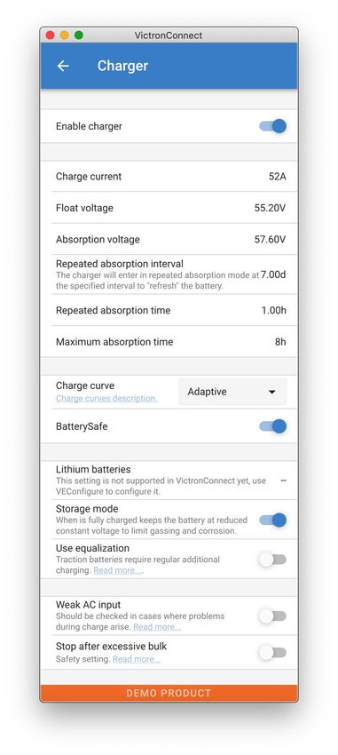
10.4. Charger
10.4.1. Enable charger
The inverter and assist functions of the Multi will continue to operate, but it will no longer charge; the charging current is therefore
zero!
100% self-consumption by disabling the charge functionality of the Multi It can be quite expensive to charge the batteries from the
grid. Lead-acid batteries have a low charge efficiency. About 20% of the energy used to charge the batteries is lost in the form of
heat. Some installers therefore prefer to disable the charger functionality of the Multi.
When the charger functionality is disabled and the Multi is accepting the grid, it will supply the loads with grid power, but will not
charge the batteries. The batteries will only receive charge from the MPPT charge controllers. In this type of system it is very
important to have a large enough solar array. It is also important that the Ignore AC battery voltage settings are set higher than
you would do normally. This is to make sure that the battery has some extra charge left should there be a blackout.
Incorrect system design can cause battery damage. Disabling the charger is only recommended in systems
that have excess solar power. If the batteries get empty during the night, the system cannot be recovered
unless you connect an external battery charger.
10.4.2. Charge current
Use this setting to specify the current with which the battery is charged during the bulk phase. Note that the actual charge current
depends on other conditions also. Therefore it is possible that the actual charge current is lower than this setting. This can,
among others, be due to a low AC input current limit in combination with a high load; high environmental temperature; too high
ripple voltage due to improper cabling. For lead batteries, the charging current should be approximately 10 to 20% of the battery
capacity. Also keep in mind the DC consumption that is expected in the system.
Page 14 Description of SettingsVictronConnect - VE.Bus Configuration guide
10.4.3. Float voltage
Use this setting to specify the Float voltage. Float stage is reduced voltage from absorption, used to trickle in current to finish
battery charge without creating excess heat or gassing.
10.4.4. Absorption voltage
Use this setting to specify the Absorption voltage. Absorption is the charge phase where the battery is held at continuous target
voltage with variable current.
10.4.5. Repeated absorption interval
Use this setting to specify the interval between repeated absorptions.
10.4.6. Repeated absorption time
Specify the duration of the repeated absorption "pulses".
10.4.7. Maximum absorption time
If the charge curve is fixed then this setting is used to determine the absorption time. In all other cases this setting determines the
maximum absorption time.
10.4.8. Charge curve
Under normal circumstances always select the adaptive mode. If the balance between the charger and battery is not ideal, it may
be better to choose fixed mode otherwise the voltage will rise too quickly or too slowly and the battery may be over or under
charged as a result.
10.4.9. BatterySafe
BatterySafe curve has a special regulation in the absorption phase. The absorption phase will start when the voltage reaches
14.4V (for a 12V battery) regardless of the specified absorption voltage. During the absorption phase the voltage will increase
with a fixed ramp until the voltage reaches the absorption voltage or until the calculated absorption time is over. In the latter case
the absorption phase will end before the absorption voltage is reached.
In a lead acid battery the charge process isn't always perfectly spread throughout the battery so therefore it can happen that when
charging fast (at the limit of what the battery can handle voltage wise), a part of the battery is already "charged" while other parts
still have the ability to absorb energy. When the charger is going "full power" to the setpoint voltage to enter absorption the
change is quite realistic that a part of the battery is getting overcharged.
BatterySafe reduces the charge current when the voltage is approaching the setpoint to enter absorption. Therefore the battery
gets a longer lifetime.
Same as for Adaptive (when the absorption period is calculated from the time the charger is in the Bulk phase), it helps extend
the lifespan of the battery.
In general, beware that the wish to charge "as fast as possible" often results in a shorter lifespan of the (lead acid) battery. Taking
it a bit slower will indeed cost fuel/time but will pay itself back in battery lifetime. Charging the battery with the generator is most
efficient in the 50-80% SOC range. So have this done daily and only go to 100% weekly as then the battery monitor is synced and
the battery gets a needed full charge.
10.4.10. Lithium battery mode
Checkbox function
The table below shows the effect of Enabling or Disabling Lithium battery mode:
Feature Lithium mode Disabled (default) Lithium mode Enabled
Temperature Lead algorithm No temperature compensation
compensation
Re-bulk voltage 1.3V less than Float-voltage, to a 0.2V less than Float-voltage, to a maximum of
maximum of 12.9V 13.5V
Note: All mentioned voltages and thresholds are for a 12V system. For 24 multiply by two; and for 48V, multiply by four. So for
example at 48V, the re-bulk mechanism for a lithium battery will use Vfloat - 0.8V with a maximum of 54V.
Temperature compensation Charge voltage are not increased or decreased within normal temperature ranges (5°C - 40°C) for
lithium batteries. Enabling Lithium mode will disable the normal built-in temperature compensation features that are used for lead
acid batteries.
Page 15 Description of SettingsVictronConnect - VE.Bus Configuration guide Re-bulk voltage The Re-bulk voltage is the point that the charger returns to the bulk charging stage. It depends upon the float voltage. Lithium batteries tend to have a more stable voltage output and a narrower voltage range than lead acid batteries, so in lithium mode the value between float and re-bulking is reduced. Required setting per lithium type A) Batteries with built-in BMS Batteries with built-in BMS, including charge and discharge interruptors, such as the Victron Superpack, Battleborn or Simplify battery brands. Also known as 'drop-in replacement' type batteries. For these types, enable the lithium battery mode; and set the charging voltages as per the battery manual. There is no need for Assistants or other configuration. B) Victron V12.8 and 25.6V batteries, requiring a VE.Bus BMS These require additional configuration that is not currently supported by VictronConnect. Please use VEConfigure instead and install the VE.Bus BMS Assistant, as well as check the Lithium battery checkbox. C) Intelligent batteries, connected to a GX-device with DVCC enabled: Checking or not checking the box doesn’t matter; it has no effect. In systems with such a battery, all charger settings are overridden by parameters coming from the CAN-bus. Examples are Victron 24V Lithiums with a Lynx BMS, BYD, Pylontech, MG Electronics, Freedomwon, Redflow, and others. 10.4.11. Storage mode With this feature active, after 24 hours in float charge, the charging voltage will be reduced below the float voltage to provide optimum protection of the battery against overcharging; charging current will continue to be applied regularly to compensate for self-discharge. This is the rest voltage if the battery is fully charged.# 10.4.12. Use equalisation For optimum charging, special traction batteries require a fixed charging current phase in addition to a voltage curve. Beware that this often results in a higher charging voltage that can be damaging to DC loads! 10.4.13. Weak AC input If the quality of the supply waveform is less than the charger expects, it will reduce its output to ensure that the COS phi (difference between current/voltage phases) remains acceptable. This protection can be deactivated for low capacity or poorly regulated power supplies. 10.4.14. Stop after excessive bulk If the absorption voltage has not been reached after 10 hours, the battery may be faulty and the charger will switch off for safety reasons. This setting will trigger the lithium battery options and wizard, depending on the configuration of your lithium battery and manufacturers advice you may need to adjust additional settings as well. 10.5. AC Input Control The AC Input Control can be set up in numerous ways, for example, the Multi will disconnect from the grid when the batteries are full enough and/or the AC load is not too big. The Multi will disconnect from the grid most of the time. It will only let the grid in when the batteries are empty or when you are running a big AC load. You now can use the grid like you would use a backup generator. The mechanism behind the AC Input Control is the opening or closing the Multi’s internal AC input relay. This feature in not enabled by default. The normal function of this relay is to open as soon as the grid or generator is not there. For example, during a blackout or when a generator is off. This is a safety action. The relay prevents energy feeding into the grid during a blackout or when the generator is off. This relay can also be setup to purposefully ignore the grid. It will still perform its normal safety action but it can open and disconnect from the grid under more situations. It can ignore the grid when the batteries are still full enough. Now DC solar power can be prioritized and the grid will be used like a backup generator 10.5.1. When can the grid be controlled? The AC input relay can be programmed to selectively ignore the grid, while looking at two parameters: It can look at battery voltage and/or at AC load parameters. The grid is ignored when the batteries are full enough. The grid is let in when the batteries are empty: • This setting can be used to charge the batteries from the grid should the batteries get too empty. This can occur, for example, at night or during a long period of bad weather. Page 16 Description of Settings
VictronConnect - VE.Bus Configuration guide

• In this scenario the Multi will look at the battery voltage. It will let the grid in when the battery voltage is too low, for a certain
  amount of time. It will ignore the grid as soon as the battery voltage has increased above a certain level, for a certain amount of
  time.
• The multi can also disconnect the grid on battery state of charge.

The grid is ignored when the AC loads are low. The grid is let in when the AC loads are high:

• This setting can be used to allow grid in when the AC load is higher than the Multi rating. This will prevent the Multi going into
  overload. This setting can also be used for large loads that you do not want to run from the battery.
• In this scenario the Multi will look at the AC load. As soon as it sees that the load is above a certain level, for a certain amount
  of time, the Multi will let the grid in. The multi will stop letting the grid in as soon as it sees that the AC load has dropped below
  a certain level, for a certain amount of time.

10.5.2. Conditional AC input activation
Enables the use of AC Input Control to modify the operation of the feedback relay.

10.5.3. Load Conditions
This setting can be used to allow grid in when the AC load is higher than the Multi rating. This will prevent the Multi going into
overload. This setting can also be used for large loads that you do not want to run from the battery.

In this example the grid will not be ignored when the load exceeds 4000 Watts, with no delay.

Do not ignore AC input means that the grid is accepted because the AC input relay is closed. The grid will be ignored when the
load drops below 2000 W.

Ignore AC means that the grid is ignored because the AC input relay is open.

Depending on your load, if the AC input relay is opening and closing frequently, add a time delay before activation and
deactivation.

AC input activation based on load

Page 17                                                                                                        Description of Settings
VictronConnect - VE.Bus Configuration guide

Activate when load is higher than W

Delay before activation T

Deactive when load is lower than W

Delay before deactivation T

10.5.4. Battery Conditions
This setting can be used to charge the batteries from the grid should the batteries get too empty. This can occur, for example, at
night or during a long period of bad weather.

In this example, the grid is not ignored when the battery voltage is less than 47 Volt. Do not ignore AC input means that the grid is
accepted because the AC input relay is closed.

The grid will be ignored again when the battery voltage exceeds 52 Volts for more than 5 minutes.

Ignore AC means that the grid is ignored because the AC input relay is open. Apart from “battery voltage”, there are two other
options to choose from: “bulk finished” or “absorption finished”.

Choosing “absorption finished” is a good way to ensure the batteries are getting a full charge every now and then. But it can lead
to a higher electricity bill. The absorption charge stage of a lead-acid battery is much less efficient than the bulk stage.

This could be a reason to choose the “bulk finished” option. At the end of the bulk charge stage a lead-acid battery is about 85%
full.

For more information about bulk and absorption please see the Victron Energy book “Energy Unlimited”, page 25. Follow this
link: https://www.victronenergy.com.au/orderbook

It is also possible to let grid in when the batteries fall below a certain state of charge.

                In a DC coupled solar system the “state of charge” option should only be used if you have a GX device in the
                system. And the GX device is connected to both the Multi and the MPPT solar charger(s) and/or a BMV
                battery monitor. In addition to this a setting needs to be made in the GX device. See this link for more
                information: https://www.victronenergy.com/live/ccgx:start#battery_state_of_charge_soc

Page 18                                                                                                     Description of Settings
VictronConnect - VE.Bus Configuration guide
11. Firmware Updates
11.1. When to do a firmware update
It is not required to keep your Victron equipment updated to the latest firmware version. Stable systems should be left with their
current firmware. Here is when to perform a firmware update:
• During commissioning / first install;
• When trouble shooting;
• To add a new feature that is required by the installation.
Firmware updates are only available in Settings Mode, requiring a password - zzz
11.2. Warning - reset to factory defaults
All settings will be reset to factory defaults after the firmware update process.
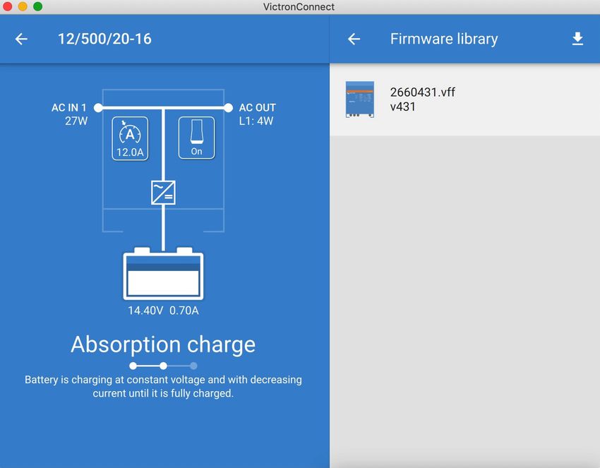
11.3. Procedure
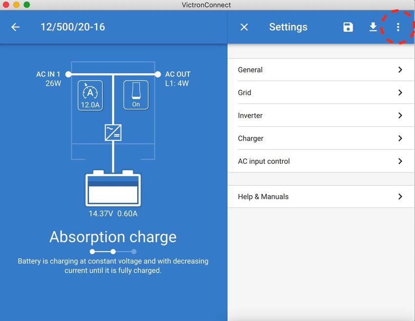
Once you are connected to the unit, enter the settings, select the Product Info from the top right dots.
VictronConnect comes with the most up to date versions of the firmware already, so an internet connection is not required.
Click update and then do not touch either device until the firmware update is complete.
There is a video of the proceedure here:
https://www.youtube.com/embed/Z9VKtoAS8o4
Step by Step:
Page 19 Firmware UpdatesVictronConnect - VE.Bus Configuration guide Page 20 Firmware Updates
VictronConnect - VE.Bus Configuration guide

If the firmware update fails, please attempt it again. If you still cannot recover the unit, Please use the alternative method
and follow these steps using the VEFlash software instead.

11.4. Firmware updates with multiple units (eg 3 phase)
It is possible to use VictronConnect to efficiently update the firmware for 3 phase, or parallel units.

To do this, the units must already be programmed for their multiple unit configuration and connected to each other.

Units will be returned to factory default settings once the firmware update is complete. So make sure that settings and parameters
are saved, and you will also need to reprogram them for their multiple unit configuration (as is covered in the 3 phase and parallel
documentation).

https://player.vimeo.com/video/373208468

Page 21                                                                                                            Firmware Updates
VictronConnect - VE.Bus Configuration guide

12. Parallel, Three, Split-phase systems

Until now our VE.Bus Quick Configure software was required to set up a complex VE.Bus System. This is not the case anymore
as VictronConnect can now be used to configure systems of up to three units.

Watch this video where we demonstrate all steps involved in configuring a three phase system in just a few clicks.

Please note a password is required for this feature, the password is available from your Victron supplier.

https://www.victronenergy.com/blog/2021/02/02/victronconnect-parallel-three-split-phase-setup-and-more/

VictronConnect allows you to change the settings of each individual MultiPlus/Quattro in an existing system. And to copy settings
from one of the inverters to the rest; as well as saving the settings of all the units to a file.

Supported features and limitations:

•   Set up Parallel, Three phase and Split phase systems. (Limited to a max of three units)
•   Configure existing systems of up to twelve or fifteen units – depending on the inverter/charger model.
•   Copy settings from one unit to the rest.
•   Save the complete system configuration to a file for future use on a similar system, and as a backup.
•   Assistants are removed when setting up a new system.
•   Firmware updating is proposed automatically when setting up a new VE.Bus system.

Page 22                                                                                      Parallel, Three, Split-phase systems
VictronConnect - VE.Bus Configuration guide

13. Troubleshooting

13.1. I am having bluetooth connection issues
If you are having difficulty with connecting to a VE.Bus device with a laptop and an MK3-USB adaptor, try the following
troubleshooting steps to help isolate the issue.

1. Make sure the device is connected to a power supply and switched on
2. Test the cable with a cable-tester and/or try another one. There can be a difference in pin arrangement in some network
   cables. The required cable is a straight-through cable, not a cross-over cable.

13.1.1. See if the MK3-USB works with a GX device.
In case you have a GX device available; you can use it to test the MK3-USB.

1.   Make sure the GX device is running v2.23 or later;
2.   The Multi should be disconnected from the GX device's VE.Bus port.
3.   Connect the MK3 USB plug into the GX's USB socket.
4.   Connect the Multi to the MK3 with network cable
5.   The Multi should appear on the GX device.

If all those do not work; the MK3 may be broken, please contact your dealer.

13.2. I am having Bluetooth connection issues
Specific VictronConnect troubleshooting assistance for Bluetooth connections is available here.

13.3. VE.Bus firmware update fails at 5% on macOS
There is a known issue that makes VE.Bus firmware updates randomly fail on some macOS laptops. We are working on it; a new
VictronConnect version fixing this issue is expected in the near future.

Meanwhile this is the workaround for this: Proceed to update as usual and quickly minimise the VictronConnect window when
progress bar is shown because the update starts. After ~20 seconds you can maximise VictronConnect to see the update status.
This issue was introduced in VictronConnect v5.9.

For those with a technical background and wondering how, why and what minimising has to do with this: yes this really works,
and relates to a power saving mode that has a side effect on serial communication.

13.4. I am having settings issues and would like to start again
You can reset the unit to the factory settings. In the Settings / Product info screen, you can update the devices firmware. This
firmware update process will reset settings to the factory default.

13.5. Still having issues?
If you have additional questions or comments after reading this document, please contact your Victron Dealer who is trained in
using this software, and has a known good testing configuration.

You can also ask for help from other Victron users at the Victron Community.

Page 23                                                                                                            Troubleshooting
You can also read