Soul kit G2+ 2 wire installation Art 7W monitor with Wi-Fi connectivity - Instructions manual - Video Türsprechanlagen ...
←
→
Page content transcription
If your browser does not render page correctly, please read the page content below

Instructions manual
                                   Soul kit
                                G2+ 2 wire installation
                                    Art 7W monitor
                                with Wi-Fi connectivity

                Cód. 50122126               TS5110 ART 7W EN REV.0119
SOUL S5110/ART 7W VIDEO INTERCOM KIT                                                                                                                                       2

 INDEX
 Index..........................................................................................................................................................................2
 Recommendations.....................................................................................................................................................3
 System operation .......................................................................................................................................................3
 FA-G2+ power supply ................................................................................................................................................4
      Description ......................................................................................................................................................4
      Installation .......................................................................................................................................................4
 Soul door panel ....................................................................................................................................................5 to 8
       Description ......................................................................................................................................................5
       Installation .......................................................................................................................................................6
       Wiring connectors ............................................................................................................................................6
       Configuration switches.....................................................................................................................................7
       Audio level adjustment .....................................................................................................................................7
       Proximity reader programming .........................................................................................................................8
 Art 7W/G2+ monitor ...........................................................................................................................................9 to 21
       Description ......................................................................................................................................................9
       Installation .....................................................................................................................................................10
       Wiring connectors ..........................................................................................................................................10
       Configuration switches...................................................................................................................................10
       Main menu .....................................................................................................................................................11
       Settings menu........................................................................................................................................12 to 15
       Communication screen ..................................................................................................................................16
       Picture and communication adjustments........................................................................................................17
       Intercom menu.......................................................................................................................................18 to 19
       Recordings menu ..................................................................................................................................20 to 21
 G2Callapp .......................................................................................................................................................22 to 29
      Initial registration of a monitor to a Wi-Fi network ....................................................................................22 to 23
      Registration of an already network connected monitor....................................................................................24
      Advanced settings of a registered monitor ..............................................................................................25 to 26
      Main screen ...................................................................................................................................................27
      Communication screen ..........................................................................................................................28 to 29
 Installation diagrams ........................................................................................................................................30 to 34
        Wiring sections and distances ........................................................................................................................30
        One apartment with one access door and one monitor....................................................................................30
        One apartment with two access doors and one monitor ..................................................................................30
        One apartment with two access doors and up to four monitors daisy chain connected.....................................31
        One apartment with two access doors and four monitors through video distributor ..........................................31
        Four apartments with two access doors and up to four monitors daisy chain connected ..................................32
        Lock release connection ................................................................................................................................33
        Relay output auxiliary device connection........................................................................................................33
        Exit button connection....................................................................................................................................34
        External CCTV camera connection................................................................................................................34
        Door bell push button connection ...................................................................................................................34
 Special codes ..................................................................................................................................................35 to 36
 Soul door panel installation template ........................................................................................................................37
 Art 7 monitor installation template.............................................................................................................................38
 Notes .......................................................................................................................................................................39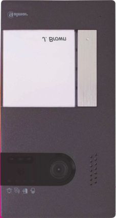
SOUL S5110/ART 7W VIDEO INTERCOM KIT                                                                                3

 RECOMMENDATIONS
 - Use, preferably, Golmar RAP-GTWIN / HF cable (2x1mm²).

 - Installation wires must be at least 40cm away of any other installation.

 - When modifications are made to the installation, do so without power.

 - The installation and handling of this equipment must be carried out by authorized personnel.

 - Check all connections before system start up.

 - Follow the instructions in this manual at all times.

 SYSTEM OPERATION
 To make the call, the visitor must press the corresponding button to the apartment with which he wishes to establish
  communication; an acoustic tone will warn that the call is being made and the led will light up. At that moment, the
  monitor (s) of the apartment receives the call. If the pushbutton of another apartment has been pressed by mistake,
  press on the one that corresponds to the desired apartment, thus canceling the first call.

 In systems with two access doors, the other door panel will be automatically disconnected: if another visitor wishes to
   call, some acoustic tones will warn that the system is busy and the led will light up.

 Upon receiving the call, the image will appear on the main monitor screen (and secondary 1, if any) without the visitor
  perceiving it. If you want to view the image from the secondary monitors 2 or 3, click on the screen to display the
  image. If the call is not answered within 30 seconds, the led will turn off and the system will be free.

 If the call transfer was programmed to your mobile phone, you can cancel the transfer at any time from the monitor,
    being necessary to contact the door panel from the main menu.

 To establish communication, click on the screen on the off-hook icon. The led on the door panel will light up. The
  communication will last for 90 seconds or until you click on the hanging icon. Once the communication is complete,
  the led will turn off and the system will be free.

 To open the door or activate the auxiliary output of the door panel, click on the corresponding icon. A single press
  activates the lock release or the auxiliary output for 3 seconds, and the led on the door panel illuminates. The
  activation time is programmable, as indicated on pages 35 to 36.

 The detailed operation of the monitor is described on pages 11 to 21.

 The owner of the apartment can activate the lock release by approaching the proximity key to the reader. If the
  proximity key is maintained for three seconds, the auxiliary relay output will be activated.
SOUL S5110/ART 7W VIDEO INTERCOM KIT 4
FA-G2+ POWER SUPPLY
Description
A B C
A. Operating light indicator.
B. Mains protection cover.
C. Mains input terminals without protection cover.
BUS(M) BUS(PL)
D. DIN rail fixing clip.
E. Wiring connectors.
D E
Installation
The installation and manipulation of the power supply must be carried out by authorized personnel and in the
absence of electric current.
Install the power supply in a dry, protected and ventilated place. Under no circumstances obstruct the ventilation
grilles. Use a DIN 46277 guide for fastening (8 elements).
Remember that the current regulations require to protect the power supply with a circuit breaker.
To avoid electric shock, do not remove the protection cover without first disconnecting the power supply. Re-install
it once all connections are complete.
Connect the cables to the wiring connectors following the indications of the installation diagrams.SOUL S5110/ART 7W VIDEO INTERCOM KIT 5
SOUL DOOR PANEL
Description
A M M
B B
C G C G
D D
E H H
F I L I
J J
K K M
A. System status icons:
Call is in progress.
In communication.
Lock release activated.
System is busy.
B. System status light indicators.
C. Light sensor.
D. Night vision illumination.
E. Protective polycarbonate.
N
Q F. Name holder and proximity reader.
O R G. Speaker grille.
H. Colour camera.
S
P I. Push button (s).
T J. Microphone hole.
O K. Fixing screw.
L. Proximity reader.
M. Wall fixing holes (x3).
N. Proximity reader sealing gasket.
O. Wiring connectors.
P. Cable gland seal.
Q. Proximity reader connector.
R. Configuration switches.
S. Audio level potentiometer.
T. Proximity reader configuration push button.SOUL S5110/ART 7W VIDEO INTERCOM KIT 6
SOUL DOOR PANEL
Installation
The door panel has been designed to withstand various environmental conditions. However, we recommend
taking additional precautions to extend its life, such as to place it in a protected place.
To obtain optimum image quality, avoid backlighting caused by light sources (sun, lampposts, ...).
For a correct installation, use the supplied template (page 37).
1. Locate the top of the template at a height of 1.65m, and make three 6mm holes at the indicated points. Insert the
supplied plugs.
2. Remove the metal front of the door panel by loosening the screw on the bottom with the key that is attached. On
the back of the front you will find the name holder label.
3. Remove the screws that hold the proximity reader and pass the installation cables through the cable gland seal.
4. Fix the door panel to the wall using the screws provided.
5. Connect the cables to the removable wiring connectors following the indications of the installation diagrams.
Before replacing the proximity reader and closing the door panel, make the necessary adjustments (programming
of proximity keys, adjusting the audio level, ...), as indicated throughout this manual. Make sure that the sealing
gasket of the proximity reader is correctly positioned.
Wiring connectors (O)
For a more comfortable installation, the wiring connectors are removable and are supplied in a separate bag. Once
the connectors are wired, place them in their position.
BUS, BUS: communication bus (polarity free).
CV-, CV+: 12Vd.c. lock release output (270mA maximum).
AP+, AP-: remote activation push button input.
ON
C, NA: voltage free relay output (6A/24V maximum).
1 2 3 4
BUS BUS CV- CV+ AP+ GND, CCTV: external analog CCTV camera input.
C NA GND CCTV AP-SOUL S5110/ART 7W VIDEO INTERCOM KIT 7
SOUL DOOR PANEL
Configuration switches (R)
Configuration changes must be made with the equipment switched off. If they are carried out with the equipment
on, disconnect it for 10 seconds after any modification.
All switches are factory-set to the OFF position.
OFF ON
Switch 1.
ON ON
Sets the door panel address.
1 2 3 4 1 2 3 4
Door panel 1 Door panel 2
* OFF-OFF ON-OFF OFF-ON
Switches 2 and 3.
ON ON ON
Set the number of apartments:
1 2 3 4 1 2 3 4 1 2 3 4
1: all push buttons call to apartment n.1.
1 apartment 2 apartments 4 apartments 2: the two lower push buttons call to apartment n.1,
* Same value than when set to ON-ON. the two upper push buttons call to apartment n.2.
4: each push button calls to a different apartment (n.1 to 4).
OFF ON
Switch 4.
ON ON
Disables door panel acoustic tones.
1 2 3 4 1 2 3 4
Enabled Disabled
Audio level adjustment
If after the start-up of the system you consider that the audio volume on the door panel is not suitable, use the
adjustment potentiometer (S). This regulation affects the audio level of the communication and that of the
confirmation tones.
ON
1 2 3 4
BUS BUS CV- CV+ AP+
C NA GND CCTV AP-SOUL S5110/ART 7W VIDEO INTERCOM KIT 8
SOUL DOOR PANEL
Proximity reader programming (L)
Make sure the equipment is powered and the reader connected to the door panel (Q).
To be able to add user keys (up to 60) in the memory of the proximity reader, it is necessary to create a
programming key and a user registration key. In order to facilitate identification, we recommend using the yellow
key to program and the blue key to register users. Use the gray ones as user keys.
Creation of programming and registration keys.
NOTE: this process completely erases the memory of the proximity reader.
Press the programming button of the proximity reader (T): the door panel will emit six short tones. Before ten
seconds approach the programming key, emitting the door panel a short confirmation tone and right after the
user registration key, issuing the door panel a long confirmation tone. If after pressing the programming
button no key is approached within ten seconds, the door panel will emit a long tone, and the memory will be
completely erased.
Once the programming and registration keys have been created, the addition and deletion of user keys can be
done with the door panel closed.
Adding user keys.
Approach the registration key to the reader: the door panel will emit four short tones. Approach one by one the
user keys that you want to add, emitting the door panel a short tone for each key added. After ten seconds
have passed since adding the last key, the door panel will emit a long tone to confirm the completion of the
process.
Deletion of an user key.
Approach the programming key to the reader: the door panel will emit four short tones. Approach the user key
that you want to delete, emitting the door panel a long tone to confirm the deletion. After ten seconds, if there
is no key to delete, the door panel will emit a long tone to confirm the completion of the process. Repeat this
process to delete other user keys.
Deletion of all user keys.
Approach the programming key to the reader: the door panel will emit four short tones. Approach the registration
key, emitting the door panel a long tone to confirm the deletion of all the keys. After ten seconds, if the
registration key has not been approached, the door panel will emit a long tone to confirm the completion of the
process.
ON
1 2 3 4
BUS BUS CV- CV+ AP+
C NA GND CCTV AP-SOUL S5110/ART 7W VIDEO INTERCOM KIT 9
ART 7W/G2+ MONITOR
Description
A
B E
C F H
G
D
I I
J
ON
UID: mnvx8d8uskpv
1 2 3 4 5 6 7 8
SA
GND
BUS
BUS
L
K HZ 24V
HZ GND
K
I I
A. Speaker. D. Orientation dots for blind people.
B. Notification icons: E. Touch screen.
Power on indication. F. Hidden push button to activate the lock.
Do not disturb. G. Microphone.
Auxiliary relay activated. H. Micro SD card slot.
Lock release activated. I. Wall bracket slots (x4).
New picture / video. J. Configuration switches.
Wi-Fi call transfer activated. K. Wiring connectors.
C. Hidden push button. Starts / ends communication. L. UID monitor sticker.SOUL S5110/ART 7W VIDEO INTERCOM KIT 10
ART 7W/G2+ MONITOR
Installation
Avoid locations near heat sources, dusty or with a lot of smoke.
For a correct installation, use the supplied template (page 38).
1. Locate the top of the template at a height of 1.65m.
2. If you are going to use an embedding box to pass the cables, match it with the holes corresponding to the chosen
box model and fix the bracket. If you prefer to fix the bracket directly on the wall, make four 6mm holes at the
indicated points; insert the supplied plugs and screw the bracket.
3. Pass the installation cables through the central hole and connect them to the removable wiring connectors
following the indications of the installation diagrams. Before connecting the wiring connectors to the monitor, set
the configuration switch as indicated below.
4. Connect the wiring connectors to the monitor and place the monitor front to the bracket, matching the slots.
Move the monitor down to fix it.
Wiring connectors (K)
For a more comfortable installation, the wiring connectors are removable and are supplied in a separate bag. Once
the connectors are wired, place them in their position.
ON BUS, BUS: communication bus (polarity free).
1 2 3 4 5 6 7 8 24V, GND: local power supply input.
SA, GND: ringer output (50mA/12V maximum).
SA BUS
HZ, HZ: doorbell push button input.
GND BUS
HZ 24V
HZ GND
Configuration switches (R)
Switches 1 to 5.
Assign the monitor address corresponding to its push button on the door panel. Switches 3 to 5 must remain in
the OFF position.
ON ON ON ON
1 2 3 4 5 6 7 8 1 2 3 4 5 6 7 8 1 2 3 4 5 6 7 8 1 2 3 4 5 6 7 8
Apartment 1 Apartment 2 Apartment 3 Apartment 4
Switches 6 and 7.
They define if the monitor is master or secondary. Each apartment must have a master monitor only. In the case
of apartments with more than one monitor, the monitor with WiFi transmitter should always be the master one.
ON ON ON ON
1 2 3 4 5 6 7 8 1 2 3 4 5 6 7 8 1 2 3 4 5 6 7 8 1 2 3 4 5 6 7 8
Master Slave 1 Slave 2 Slave 3
Switch 8.
Loads the monitor with the end of line resistor when set to ON. Activate it on those monitors where the bus cable
path ends. Deactivate it only in the intermediate monitors.SOUL S5110/ART 7W VIDEO INTERCOM KIT 11
ART 7W/G2+ MONITOR
Main menu
31-01-2019 Wed
09:27 PM
Door panel Intercom Recordings Settings
If the monitor is on standby mode (screen off), touch anywhere on the screen to activate it and the main menu will
appear. The monitor will return to the standby mode after 1 minute without activity.
It allows to see the image coming from the door panels and cameras connected to the system
It access to the intercom menu with other system monitors.
Displays the list of images recorded in the monitor's memory. If there are new images or some are not
yet displayed, the quantity will be shown in the upper right part of the icon. If the amount is greater
than 9, three points will be shown.
2 ...
Allows to change system settings.
Switches off the monitor screen. Apaga la pantalla del monitor.
Indicates that the inserted micro SD card must be formatted from the monitor. Press to access the
storage menu and format the card.
Press to enable or disable Wi-Fi transmission. The icon will change color (enabled white, disabled off)
and the notification icon will light depending on the status.
Only the master monitor can activate the Wi-Fi transmission.
Changes the image recording mode during the reception of the call: no recording,
snapshot picture or video. Video mode is only available when a micro SD card
is inserted.
Press to enable or disable the "Do not disturb" function (the monitor does not ring when a
call is received). The notification icon will light depending on the status.SOUL S5110/ART 7W VIDEO INTERCOM KIT 12
ART 7W/G2+ MONITOR
Settings menu
Settings
Language Time & Date Ringtone Background
Do not disturb Storage WiFi About
Use icon to return to the main menu.
It allows you to choose one of the 16 available languages for the user interface. Once chosen, confirm
your selection with the icon, returning the monitor to the settings menu.
Language
ﺑ"ﺔ$اﻟﻌ Čeština Dansk Deutsch
English Español Eλληνικά Français
Italiano Magyar Nederlands Norsk
Português русский Slovenský SvenskaSOUL S5110/ART 7W VIDEO INTERCOM KIT 13
ART 7W/G2+ MONITOR
Settings menu
It allows to adjust the date and time of the system, as well as the presentation format. Change the
values by sliding up or down, and use the arrows to change the formats. Validate the changes
made with the icon, returning the monitor to the settings menu.
Time & Date
Year Month Day Hour Min
2021 01 21 23 13
2022 02 22 00 14
2023 03 23 01 15
22 / 02 / 2022 24H
In order to distinguish the origin of the calls when you are not in front of the monitor, choose different
melodies using the arrows. Once chosen, confirm your selection with the icon.
Ringtone
Door panel 1 1/6
Door panel 2 3/6
Doorbell 5/6
Intercom 6/6
Personalize the monitor with one of the six available coloured backgrounds. Select your favorite and
validate the changes made with the icon , returning the monitor to the settings menu.
BackgroundSOUL S5110/ART 7W VIDEO INTERCOM KIT 14
ART 7W/G2+ MONITOR
Settings menu
In the "Do Not Disturb" settings you can set a time period in which the monitor will not ring when
receiving calls. To do this, activate the timer function and choose the time period. From the main
menu you can activate and deactivate the "Do not disturb" function regardless of the timer status.
If you do not want to be contacted from another monitor, you can deactivate the intercom function. If
you do, you can not contact other monitors either.
Validate the changes made with the icon , returning the monitor to the settings menu.
Do not disturb
Timer
Hour Min Hour Min
23 13 23 13
00 14 00 14
01 15 01 15
Intercom enabled
In some countries, the law does not allow the storage of images or videos for more than 30 days after
recording. The automatic erase function performs this task for you. You can deactivate this function
in the case of the legislation of your country does not demand it, or under your responsibility.
If you have not inserted a micro SD card into the monitor, only snapshot pictures can be recorded in
the monitor's internal memory (up to 100). If you have inserted one, the images and videos will
always be recorded on the card, and the images in the internal memory can not be displayed until
you copy them on the card.
From this menu you can delete the contents, copy the internal memory to the SD card and format the
card. Any of these actions will require your confirmation.
Use icon to return to the settings menu.
Storage
Automatic erasing
Picture Copy Picture Video Format
Internal memory Micro SDSOUL S5110/ART 7W VIDEO INTERCOM KIT 15
ART 7W/G2+ MONITOR
Settings menu
During the first system start-up, we recommend to restart the Wi-Fi parameters using the icon.
Remember that only the master monitor can activate the Wi-Fi transmission.
The Wi-Fi menu shows information about the identity of the monitor (UID), the name of the network to
which it is connected (SSID) and the signal strength. Use G2Call application to connect the
monitor to your Wi-Fi network as detailed below.
Choose, using the arrows, the time you want to elapse between the reception of the call from the door
panel and the start of the transfer of the call to the mobile phone. Validate the changes made with
the icon , returning the monitor to the settings menu.
Wi-Fi
Call forwarding delay 05 s
UID v PK s0d9tvru
SSID Golmar WiFi
The "About" screen provides information about the equipment, such as the monitor version and its
address.
Click on the icons to display the QR code that will take you to the updated downloads of this
instruction manual and the G2Call application for your mobile phone.
Use the icon to restore factory settings, such as language, melodies, ... The Wi-Fi parameters will
not be modified.
Use the icon to return to the settings menu.
About
Instructions manual
App
FW version 1.03
Monitor address 028 / S2SOUL S5110/ART 7W VIDEO INTERCOM KIT 16
ART 7W/G2+ MONITOR
Communication screen
02-02-2222 11:17:10 Door panel 1
2
1
This screen is displayed when you receive a call or when you press icon from the main menu. The date and
time are shown in the top center of the screen, and the source of the image (door panel 1, door panel 2, camera 1
or camera 2) is shown on the right. After 10 seconds without activity, the icons will disappear; tap anywhere on
the screen to reappear.
Cancels the call or display in progress and returns to the main menu.
Access to the picture and communication settings menu.
Change the image source, as long as the system has more than one door panel or has an external
camera connected and their visualization has been activated (see page 35). It is possible to
change the image source at any time.
Starts or ends audio communication with the displayed door panel. The communication
has a maximum duration of 90 seconds. Once the communication is finished, the
screen will turn off.
Activates the lock release (or device connected to the CV output of the door panel) for 3 seconds
1 (factory value, programmable by the installer). During activation, the notification icon will light.
Activates the lock release (or device connected to the relay output of the door panel) for 3 seconds
2 (factory value, programmable by the installer). During activation, the notification icon will light.
In case of having a micro SD card inserted, starts recording a video of 15 seconds. Otherwise, it will
take a snapshot picture. The notification icon will light.
Takes a snapshot picture. The notification icon will light.SOUL S5110/ART 7W VIDEO INTERCOM KIT 17
ART 7W/G2+ MONITOR
Picture and communication adjustments
02-02-2222 11:17:10 Door panel 1
2
1
02-02-2222 11:17:10 Door panel 1
2
1
During the visualization or communication process, it is possible to adjust the parameters of the image (brightness,
contrast and color), the volume of the ringing tone (during visualization) and the audio level of the speaker
(during communication).
Press the icon and use the sliders to make the adjustments. Clicking on the icon again, the settings window will
disappear.SOUL S5110/ART 7W VIDEO INTERCOM KIT 18
ART 7W/G2+ MONITOR
Intercom menu
From this menu you can communicate with other monitors of your apartment (internal intercom) or your building
(external intercom). To do this, your monitor and the called one must have activated the intercom function from
the "Do not disturb" menu.
Use and icons to switch between internal and external intercom screens.
If during the intercom process with another monitor a call is received from the door panel, the intercom process will
be terminated, and the call from the door panel will be received on the corresponding monitor.
Use icon to return to the main menu.
Intercom
Calling ...
Master All
Slave 1
Slave 2
Slave 3
Internal intercom.
Select the monitor with which you want to communicate. The monitor that appears selected by default it’s yours.
You will find information about the monitor's address in the "About" menu. If you select the "All" option, the rest
of the monitors will receive the call, establishing communication with the first one that responds.
To make the call, press on the icon, the message "Calling ..." appears on the screen. The monitor or
monitors that receive the call will display the message "Calling from", followed by the calling monitor address.
To cancel the call press on the icon, appearing the message "Call finished”.SOUL S5110/ART 7W VIDEO INTERCOM KIT 19
ART 7W/G2+ MONITOR
Intercom menu
Intercom
028
1 2 3
4 5 6
7 8 9
0
External intercom.
Enter the code of the apartment with which you wish to communicate using the keypad.
To make the call, press on the icon, the message "Calling ..." appears on the screen. The main monitor of the
called apartment will show the message "Calling from", followed by the calling monitor address. To cancel the
call press on the icon, appearing the message "Call finished".SOUL S5110/ART 7W VIDEO INTERCOM KIT 20
ART 7W/G2+ MONITOR
Recordings menu
Displays the list of pictures saved on the monitor or on the SD card, if installed. The icon allows us to access
the video recordings stored on the SD card, and can return to the list of images using the icon. The number
of recordings per page is 10, showing the number of pages at the top of the screen. Use the scroll arrows to
access the rest of the pages.
The symbol indicates that the recording has not been displayed.
Use icon to return to the main menu.
Picture
01 / 03
20-02-2019 18:12:23 11-02-2019 20:27:25
20-02-2019 12:27:22 08-02-2019 11:17:10
17-02-2019 16:41:33 04-02-2019 15:43:50
15-02-2019 09:55:42 01-02-2019 22:11:00
12-02-2019 23:00:00 22-01-2019 08:07:06
To delete one or more recordings from the list, use the icon. Click on the recordings you want to delete or use
the icon to select them all. Confirm your selection using the icon: a warning screen will ask for your final
confirmation.
Use icon to return to the recordings list.
Picture
01 / 03
02-02-2222 11:17:10 02-02-2222 11:17:10
02-02-2222 11:17:10 02-02-2222 11:17:10
02-02-2222 11:17:10 02-02-2222 11:17:10
02-02-2222 11:17:10 02-02-2222 11:17:10
02-02-2222 11:17:10 02-02-2222 11:17:10SOUL S5110/ART 7W VIDEO INTERCOM KIT 21
ART 7W/G2+ MONITOR
Recordings menu
To view a recording, click on it in the list. The recording will be displayed in full screen. Use the scroll arrows to show
the next ( ) or previous ( ) recording. From this screen you can also delete the recordings individually,
always requiring confirmation. Use the icon to play the pictures in sequence; if it is a video, the recording will
start playing. Tap the screen to stop playback.
Use icon to return to the recordings list.
014 / 020 02-02-2222 11:17:10 Door panel 1SOUL S5110/ART 7W VIDEO INTERCOM KIT 22
G2Call APP
Initial registration of a monitor to a Wi-Fi network
To register the monitor in the Wi-Fi network of your home, it will be necessary to download and install the G2Call
application on your phone. The application is available for Android® and iOSTM operating systems and can be
downloaded for free from Google Play and Apple Store respectively.
Start the application once installed on your phone. Read carefully the terms and conditions of use of the
application: you can access it after accepting them. The application will request permission to access certain
functions of the phone, such as the use of the loudspeaker, the microphone, ... You must give your authorization
for the correct operation of the application.
During the registration process, some phones experience problems while they are connected to the mobile phone
network. We recommend that you put your mobile in airplane mode, with Wi-Fi activated, during the registration
process.
Activate the Wi-Fi functionality of the main monitor using the icon from the main menu. Go to the Wi-Fi screen in
the settings menu and check that the pairing signal appears in the upper right part of the screen.
To start the registration, click on the "Add monitor" option. If there is already a monitor registered on your phone,
click on the + icon to add a new monitor. Then click on the option "New monitor", since it is the first time the
monitor is registered in the network of your home; if the monitor was previously registered in another network,
restart the Wi-Fi settings as indicated on page 15. Leave the application screen in the background and activate
the Wi-Fi of your phone; connect to the network that starts with "UID", return to the application screen and press
"Next".
Select the Wi-Fi network to which you will connect your monitor. In case of more than one network, select the one
closest to your monitor. Note: due to restrictions of the iOS operating system, it is not possible to display the list
of available networks (see next page).
Monitors Add monitor New monitor New monitor
If your Wi-Fi monitor has been con- Which Wi-Fi network
1 figured before, reset its Wi-Fi settings should your monitor
by following the instructions manual connect to?
If you have more than one,
Turn on your smartphone Wi-Fi and select the nearest network
2 look for available networks to your monitor location.
+
New monitor Connect to the network starting with
3 " UID ” UID ae01096a7e
MyWiFi MyWiFi
Connected
Add monitor Monitor connected to network UIDae01096a7e MyWiFi_2
TP-Link
Next
DL ink
Android only screenSOUL S5110/ART 7W VIDEO INTERCOM KIT 23
G2Call APP
Initial registration of a monitor to a Wi-Fi network
Enter the password for accessing the network. If you are registering on a device with an iOS operating system,
manually enter the SSID identifier of the network. Pressing "Next" will start the pairing process, which can take
up to two and a half minutes.
If the pairing process ends successfully, the basic monitor configuration screen will be displayed. Give it a name to
differentiate it from other possible monitors registered on your phone. The factory default for the connection
password is "1234." This password can only be changed once the monitor is registered. If the monitor is
connected to a second door panel or CCTV cameras, indicate it.
If, on the contrary, the pairing process failed, go to the Wi-Fi screen of the monitor settings menu and verify that it’s
connected to your Wi-Fi network: the name of your network should appear in the SSID field and the upper right
of the screen should show the intensity bars of the connection signal. In affirmative case, register the monitor
with the option "Monitor connected to the network".
Once the process is finished, the registered monitor will appear as available.
New monitor New monitor New monitor Monitors
+
Villa
Enter Wi-Fi password for Enter Wi-Fi network Name Casa
your monitor should
“MyWiFi” connect to.
UID ae01096a7e
If you have more than one,
select the nearest network
to your monitor location. Password
Door panels 1 2
SSID MyWiFi Cameras 0 1 2
Password
Next Next
Android only screen iOS only screenSOUL S5110/ART 7W VIDEO INTERCOM KIT 24
G2Call APP
Registration of an already connected monitor
Make sure your phone has connectivity, either Wi-Fi or through your telephone network provider. Click on the "Add
monitor" option or on the + icon to add a new monitor. Then click on the option "Monitor connected to the
network". You can choose between searching for monitors connected to your network, being necessary the
phone connected to it, or enter network data manually.
If you choose the "Search" option, the application will show you the identifiers (UID) of the connected monitors.
Select the monitor you want to register in your application, showing the basic monitor configuration screen.
If you choose the "Add manually" option, you can scan the QR code located on the back of the monitor with your
phone, or manually enter the UID (that can be found in the Wi-Fi screen of the settings menu) in the basic
configuration screen of the monitor.
Once the process is finished, the registered monitor will appear as available.
Monitor connected Connected monitors Add manually New monitor
Select from the list Click to scan QR code Name Office
the monitor located on the back cover
you want connect to. of the monitor ...
UID vksp9p6k8ztu
Password
Search Door panels 1 2
UID ae01096a7e
Cameras 0 1 2
UID vksp9p6k8ztu
Add manually
UID 93ztys5jj72a
... or
Enter UIDSOUL S5110/ART 7W VIDEO INTERCOM KIT 25
G2Call APP
Advanced settings of a registered monitor
To access the advanced settings of a monitor registered in the application, click on the preview screen of that
monitor and then on the icon on the top right of the screen. Even if the monitor is not connected at that
moment, you can adjust the settings.
ID.
To make changes to the basic settings of the monitor, receiving notifications from the previous screen must be
disabled. In addition to the basic monitor settings described on page 23, you can activate the password
request function to open the door. This password is the same as that of the basic monitor settings, and can be
changed from the advanced settings. This password will be requested to disable the function again.
Use to change the settings. Once changes are made, save changes using icon. If you want to discard
changes made, use icon.
Password.
It allows to change the connection password to the monitor. It is the same password used to open the door if the
function has been activated. Once the password has been changed, save the changes using the icon. If
you want to discard changes made, use icon.
Note: this password is stored in the monitor. In case of that other phone has registered this monitor too, it will be
necessary to apply the password change on the basic settings of this monitor too.
Push to talk.
The application has hands-free communication with the door panel. If you prefer, you can activate the "Push to
talk" function by clicking on the box.
Preview.
Sets the quality of the video signal by default (number of images per second) to adapt it to the type of data
connection. It also defines if the audio from the door panel to the phone is activated automatically upon
receipt of the call, or on the contrary it is necessary to click on the pick-up icon.
Monitor settings ID Password Preview
ID Name Villa Current 1 to 15 numbers Audio
Password UID UID New 1 to 15 numbers Video Quality High
Push to talk Password Confirm 1 to 15 numbers Mid
Preview PIN to unlock Low
Wi-Fi Door panels 1 2
Notification Cameras 0 1 2
FW version
Time & Date syncronization
DeleteSOUL S5110/ART 7W VIDEO INTERCOM KIT 26
G2Call APP
Advanced settings of a registered monitor
Wi-Fi.
It allows you to change the Wi-Fi network to which the monitor is connected by another one available in your
environment.
Note: due to restrictions of the iOS operating system, it is not possible to display the list of available networks,
being necessary to manually enter the SSID identifier of the network.
Network change can only be done when the phone is in the same location as the monitor.
Notification.
To be able to receive call transfers from this monitor, it will be necessary to activate the notification function.
Disable this function if all you want is to connect to the system without being called.
FW version.
It shows the FW version of this monitor and the latest version on the remote communications server, being
possible to update it. The application informs of the availability of a FW version by means of a warning on the
icon of advanced configuration of the monitor.
Date & Time syncronization.
It allows to update the date and time of the monitor with the data of the telephone.
Delete.
It deletes the monitor from the application. The reception of notifications must be disabled for deletion.
FW version
Current version V500R001B009
Latest version V500R001B009
UpdateSOUL S5110/ART 7W VIDEO INTERCOM KIT 27
G2Call APP
Main screen
When running the application, and after the welcome screen, the selection screen of the connected monitors is
displayed. Those that have connectivity will show the icon. To visualize the image coming from one of the
systems, press on the registered monitor, accessing the communication screen (see next page).
If you click on the icon you will access the events screen. This screen shows the list of events: answered calls,
missed calls and door openings. Each event shows the door panel number between parentheses and the time it
occurred. Swipe the screen down to update the list. By clicking on the icon you can delete the events that you
select, or all simultaneously using the icon.
The icon will take you to the screen that shows the snapshot pictures or videos recorded from the application.
Click on any of the recordings to view it in full screen, from where you can also share or delete it individually. By
clicking on the icon you can delete and share several or all of the recordings simultaneously. To do this, use
, and icons.
To access the application settings press the icon. From here you can select if you want the phone to ring and /
or vibrate when you receive a call. By clicking on the icon you can view the version of this application as well
as Golmar's privacy policy. In the case of Android devices, exit the application using the icon or force its
closure: it will continue to receive calls and the application will not consume battery.
Monitors
+ Events Recordings Main settings
Villa 2018-06-13
Villa (1) 2018-06-13 16:25:19 2018-06-13 17:45:39 2018-06-13 18:12:00
Sound
2018-06-13 19:17:18
Office (2)
Vibration
2018-06-13 19:17:18
Villa (1)
1
2018-06-13 19:17:18
Villa (1)
2
2018-06-13 19:17:18
Office
ExitSOUL S5110/ART 7W VIDEO INTERCOM KIT 28
G2Call APP
Communication screen
If you have activated the call transfer on the monitor and the notifications are activated in the application, you will
receive the calls made on the entrance panel. A pop-up screen will show you the origin of the call. You can
accept the call through the icon, or reject it by pressing . Once the call is accepted, you can establish
audio communication by pressing the icon .
Whether you access the communication screen via a call reception or access from the main screen, the options
detailed below will be the same.
Villa Villa Villa
2018-06-13 17:45:39 2018-06-13 17:45:39 2018-06-13 17:45:39
Villa 1
Door panel 1 Door panel 1 Door panel 1
Push to talk
2 1 2 1
2 1
Enables or disables the audio coming from the door panel during the viewing process. The
initial state depends on the monitor preview settings (page 25).
Activate or deactivate the phone's microphone during the communication process. In the
communication mode "Push to talk" is deactivated.
Takes a snapshot picture.
Press to start recording a video. To end the recording, press the icon again.
Change the source of the image. This icon appears in case the system has more than one door panel
or has an external camera connected, and has been configured in the basic settings of the monitor
(pages 23 to 25). It is possible to change the source during the visualization and communication
processes.
Start or end audio communication with the displayed door panel. The communication has a
maximum duration of 90 seconds.
In the "Push to talk" communication mode, keep it pressed while talking and release to listen.SOUL S5110/ART 7W VIDEO INTERCOM KIT 29
G2Call APP
Communication screen
Villa
2018-06-13 17:45:39
Door panel 1
1 2 3 4 5
6 7 8 9 0
Activates the door opener or device connected to the CV output of the displayed door panel or
camera. It will be necessary to enter a password for activation if you defined it on page 25.
1
Activates the door opener or device connected to the relay output of the displayed door panel or
camera. It will be necessary to enter a password for activation if you defined it on page 25.
2
It allows to change the quality of the video signal to adapt it to the type of data
connection.
Switches between full screen mode (horizontal orientation of the phone) and normal screen
mode (portrait orientation).
1 2 3 4 5
6 7 8 9 0
2 1SOUL S5110/ART 7W VIDEO INTERCOM KIT 30
INSTALLATION DIAGRAMS
Wiring sections and distances
- The maximum number of monitors per apartment is 4.
- The maximum number of monitors connected in daisy chain configuration is 12.
Cable type A B C
2 x 0,75mm² (AWG18) 30 m 30 m 15 m
CAT5 60 m 60 m 30 m
RAP-GTWIN/HF 60 m 60 m 30 m
A. Distance between power supply and the farthest door panel.
B. Distance between power supply and the farthest monitor (or video distributor).
C. Distance between video distributor and the farthest monitor connected to one of its outputs.
One apartment with one access door and one monitor
ON ON
Mains 1 2 3 4
1 2 3 4 5 6 7 8
100~240Vac
DOOR PANEL 1
APARTMENT 1
MASTER MONITOR
N L
BUS BUS BUS (M) BUS (PL) BUS BUS
One apartment with two access doors and one monitor
ON ON ON
Mains 1 2 3 4 1 2 3 4
1 2 3 4 5 6 7 8
100~240Vac
DOOR PANEL 2 DOOR PANEL 1
APARTMENT 1
MASTER MONITOR
N L
BUS BUS BUS (M) BUS (PL) BUS BUS BUS BUSSOUL S5110/ART 7W VIDEO INTERCOM KIT 31
INSTALLATION DIAGRAMS
One apartment with two access doors and up to four monitors daisy chain connected
ON ON ON ON ON
Mains 1 2 3 4 1 2 3 4
1 2 3 4 5 6 7 8 1 2 3 4 5 6 7 8 1 2 3 4 5 6 7 8
100~240Vac
DOOR PANEL 2 DOOR PANEL 1
APARTMENT 1 APARTMENT 1 APARTMENT 1
MASTER MONITOR SLAVE 1 MONITOR SLAVE 3 MONITOR
N L
BUS BUS BUS BUS BUS BUS BUS (M) BUS (PL) BUS BUS BUS BUS
One apartment with two access doors and four monitors through video distributor
ON ON ON ON
1 2 3 4 5 6 7 8 1 2 3 4 5 6 7 8 1 2 3 4 5 6 7 8 1 2 3 4 5 6 7 8
APARTMENT 1 APARTMENT 1 APARTMENT 1 APARTMENT 1
MASTER MONITOR SLAVE 1 MONITOR SLAVE 2 MONITOR SLAVE 3 MONITOR
BUS BUS BUS BUS BUS BUS BUS BUS
BUS out A BUS out B BUS out C BUS out D
ON
D4L-ART
BUS IN BUS IN
ON ON
Mains 1 2 3 4 1 2 3 4
100~240Vac
DOOR PANEL 2 DOOR PANEL 1
N L
BUS (M) BUS (PL) BUS BUS BUS BUSSOUL S5110/ART 7W VIDEO INTERCOM KIT 32
INSTALLATION DIAGRAMS
Four apartments with two access doors and up to four monitors daisy chain connected
ON ON ON ON
Mains
1 2 3 4 5 6 7 8 1 2 3 4 5 6 7 8 1 2 3 4 5 6 7 8 1 2 3 4 5 6 7 8
100~240Vac
APARTMENT 2 APARTMENT 2 APARTMENT 2 APARTMENT 2
MASTER MONITOR SLAVE 1 MONITOR SLAVE 2 MONITOR SLAVE 3 MONITOR
N L
(*)
BUS BUS 24V GND + BUS BUS BUS BUS BUS BUS
ON ON ON ON
Mains
1 2 3 4 5 6 7 8 1 2 3 4 5 6 7 8 1 2 3 4 5 6 7 8 1 2 3 4 5 6 7 8
100~240Vac
APARTMENT 1 APARTMENT 1 APARTMENT 1 APARTMENT 1
MASTER MONITOR SLAVE 1 MONITOR SLAVE 2 MONITOR SLAVE 3 MONITOR
N L
(*)
BUS BUS 24V GND + BUS BUS BUS BUS BUS BUS
APARTMENT 4
ON ON
APARTMENT 3
Mains 1 2 3 4 1 2 3 4
100~240Vac
DOOR PANEL 2 DOOR PANEL 1
BUS out A BUS out B BUS out C BUS out D N L
ON
D4L-ART
BUS IN BUS IN BUS (M) BUS (PL) BUS BUS BUS BUS
(*) FA-ART 7W power supplySOUL S5110/ART 7W VIDEO INTERCOM KIT 33
INSTALLATION DIAGRAMS
Lock release connection
The drawing shows the connection of a 12Vd.c. lock release, with a maximum consumption of 270mA. The use of
the Golmar CV-14 / DC, CV-24 / DC, CV-14P / UNI or CV-24P / UNI models is recommended. Activation is
done through the 1 icon.
The activation time is 3 seconds, it being possible to adjust it between 0.5 and 10 seconds (see page 36).
BUS BUS CV- CV+ AP+
If the lock release you are going to use is AC, use a relay and a transformer suitable for consumption. The example
shows a Golmar SAR-12/24 relay and a TF-104 transformer (12Va.c./1.5A).
Mains
100~240Vac
PRI PRI
SEC SEC NC NA C IN IN BUS BUS CV- CV+ AP+
Relay output auxiliary device connection
The drawing shows, as an example, the connection of a second AC lock release. The relay can switch loads of 6A /
24V. Activation is done through the 2 icon.
The activation time is 3 seconds, it being possible to adjust it between 0.5 and 10 seconds (see page 36).
Mains
100~240Vac
PRI PRI
SEC SEC C NA GND CCTV AP-SOUL S5110/ART 7W VIDEO INTERCOM KIT 34
INSTALLATION DIAGRAMS
Exit button connection
The exit button allows the remote activation of the lock release connected between the CV- and CV + terminals (by
default) or the relay output (see page 36). The delay time for activation is 3 seconds, it being possible to adjust it
between 0.5 and 10 seconds (see page 36).
BUS BUS CV- CV+ AP+
C NA GND CCTV AP-
External CCTV camera connection
It is possible to connect an analog CCTV camera to each of the door panels, and they can be viewed (see page 35)
from the monitor or the mobile application. The camera must have local power.
BUS BUS CV- CV+ AP+
C NA GND CCTV AP-
Doorbell push button connection
Connect the doorbell push button to the HZ inputs of the monitor you want to ring.
HZ HZSOUL S5110/ART 7W VIDEO INTERCOM KIT 35
SPECIAL CODES
The activation of some functions, as well as to modify some factory parameters, can be carried out by entering special
codes. To do this you must access the installer menu from the monitor. Go to the "About" screen in the settings menu
(page 15) and press five consecutive times on the icon at the top right of the screen, appearing a keyboard for
entering the codes.
The codes must be entered one by one, preceded by the asterisk symbol and validated by the icon. If the code
entered is valid, the message OK will be displayed; otherwise the message ERROR will be displayed.
When the parameter of a door panel is modified, it affects to all door panels. The parameters modified in one monitor
do not affect the rest of the monitors.
Use icon to return to the main menu.
*128
1 2 3
4 5 6
7 8 9
0
Video sources available in the monitor.
Available Not Available Factory value
Door panel 1 *111 *110 *111
Door panel 2 *121 *120 *120
Camera 1 *141 *140 *140
Camera 2 *181 *180 *180
Automatic lock activation when a call is received on the monitor.
Enabled Disabled Factory value
*441 *440 *440SOUL S5110/ART 7W VIDEO INTERCOM KIT 36
SPECIAL CODES
Outputs activation time.
Factory value
Lock release From *200 (0,5s) up to *219 (10s) *203 (3s)
Relay From *300 (0,5s) up to *319 (10s) *303 (3s)
Remote activation input configuration.
Factory value
Delay From *400 (0,5s) up to *419 (10s) *403 (3s)
Operating output *430 (lock release) or *431 (relay) *430 (lock release)SOUL S5110/ART 7W VIDEO INTERCOM KIT 37 SOUL DOOR PANEL INSTALLATION TEMPLATE
SOUL S5110/ART 7W VIDEO INTERCOM KIT   38

 ART 7 MONITOR INSTALLATION TEMPLATE
SOUL S5110/ART 7W VIDEO INTERCOM KIT   39

 NOTES
Sistemas de comunicación S.A.

                        golmar@golmar.es
                          www.golmar.es

                          GOLMAR S.A.
                            C/ Silici, 13
                    08940- Cornellá de Llobregat
                              SPAIN

Golmar se reserva el derecho a cualquier modificación sin previo aviso.
    Golmar se réserve le droit de toute modification sans préavis.
Golmar reserves the right to make any modifications without prior notice.
You can also read