JPC 100-WEB Smart Energy Panel - www .janitza.de
←
→
Page content transcription
If your browser does not render page correctly, please read the page content below
Smart Energy Panel
                                                         JPC 100-WEB
                                                         User manual and technical specifications
                         www.janitza.de
09/2021
Doc. no. 2.100.045.1.c

                         Janitza electronics GmbH
                         Vor dem Polstück 6
                         D-35633 Lahnau
                         Support tel. +49 6441 9642-22
                         email: info@janitza.de
                         www.janitza.com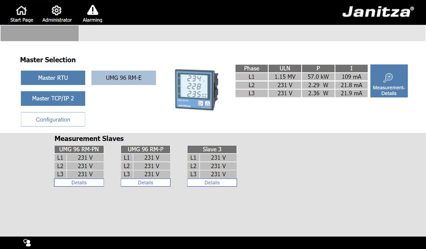
JPC 100-WEB                                      www.janitza.de

          Table of contents

          1.     General                                    4

          1. 1   Disclaimer                                 4
          1. 2   Copyright notice                           4
          1. 3   Technical changes                          4
          1. 4   Conformity declaration                     4
          1. 5   Comments on the manual                     4

          2.     Safety                                     5

          2. 1   Safety information                         5
          2. 2   Safety measures                            6
          2. 3   Qualified personnel                        6

          3.     Product description                        7

          3. 1   Scope of performance                       7
          3. 2   Operating concept                          7
          3. 3   Incoming goods inspection                  7
          3. 4   Scope of delivery                          7
          3. 5   Intend use                                 8
          3. 6   Supported measuring devices                8

          4.     Mounting                                   10

          4. 1   Installation location                      10
          4. 2   Mounting orientation                       10
          4. 3   Securing                                   11

          5.     Installation                               12

          5. 1   Circuit breaker                            12
          5. 2   Supply voltage                             12
          5. 3   Connection to a master device              12
          5. 4   Connection as a master device              12

          6.     Introduction to operation                  13

          6. 1   Start page                                 14
          6. 2   Remote access                              14
          6. 3   Log in                                     14

2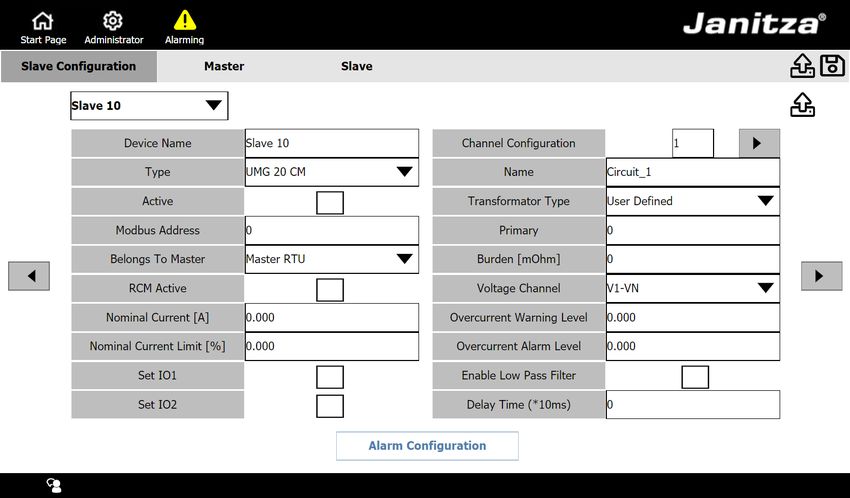
www.janitza.de                                           JPC 100-WEB

7.        Settings                                   15

7. 1      System                                     15
7. 1. 1   Device                                     16
7. 1. 2   Modbus TCP                                 17
7. 1. 3   TCP/IP                                     17
7. 1. 4   NTP / Clock                                18
7. 1. 5   Ping testing                               18
7. 2      Users (login to the system)                19
7. 2. 1   User management                            20
7. 3      Emailing                                   21

8.        Alarming                                   22

9.        Configuration                              23
9. 1      Master devices                             24
9. 1. 1   Integrating a new master device            25
9. 1. 2   Using the JPC 100-WEB as a master device   25
9. 2      Slave devices                              26
9. 2. 1   Integrating a new slave device             27
9. 2. 2   Configuring the UMG 20 CM                  27
9. 3      Alarms and warnings                        28

10.       Service and maintenance                    29

10. 1     Remote access via TeamViewer               29
10. 2     Repairs and calibration                    29
10. 3     Front panel foil                           29
10. 4     Disposal                                   29
10. 5     Service                                    29

11.       Technical data                             30
11. 1     Dimensional drawings                       31

                                                                  3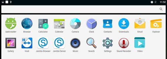
JPC 100-WEB                                                                            www.janitza.de

          1.       General

          1. 1 Disclaimer                                    1. 5 Comments on the manual
          Compliance with the informational products         Your comments are welcome. If anything
          for the device is a prerequisite for safe oper-    in this manual seems unclear, please let us
          ation and attaining the stated performance         know and send us an email at:
          characteristics and product features. Janitza
          electronics GmbH assumes no liability for           info@janitza.de
          bodily injury, material damage or financial
          losses which result from disregard of the
          informational products.

          Ensure that your informational products are
          readily accessible in a legible form.

          1. 2 Copyright notice
          © 2019 - Janitza electronics GmbH - Lahnau.
          All rights reserved.

          Any reproduction, processing, distribution or
          other use, in whole or in part, is prohibited.

          All trademarks and the rights arising from
          them are the property of the respective own-
          ers of these rights.

          1. 3 Technical changes
           • Make sure that your device matches the
             installation instructions.
           • First read and understand the documents
             associated with the product.
           • Keep the documents associated with the
             product available for the entire service life
             and pass them on to any possible subse-
             quent users.
           • Find out about device revisions and the
             associated modifications of the documen-
             tation associated with your product at
             www.janitza.de.

          1. 4 Conformity declaration
          The laws, standards and directives applied
          by Janitza electronics GmbH for the device
          can be found in the declaration of conformity
          at www.janitza.de.

4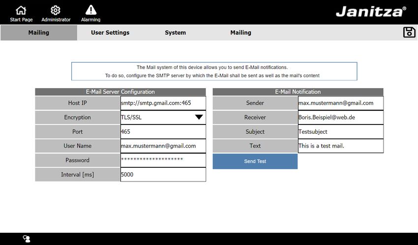
www.janitza.de                                                                                  JPC 100-WEB

2.       Safety

Please read this user manual and all other        2. 1   Safety information
publications that must be consulted when
working with this product. This applies in                           NOTE
particular to installation, operation and main-   Indicates procedures in which there is no
tenance.                                          hazard of injury or material damage.

Please observe all safety regulations and
warnings. If notices are disregarded, this can
lead to personal injury and/or damage to the
                                                                  ATTENTION
product.                                          Draws attention to an immediately hazardous
                                                  situation which, when disregarded, can lead
Any unauthorized modification or use of this      to material or environmental damage.
device beyond the specified mechanical,
electrical or other operating limits can cause    Safety information is marked by a warning
personal injury and/or damage to the prod-        triangle and, in dependence on the degree of
uct.                                              hazard, is displayed as follows:

Any such unauthorized modification consti-
                                                                      DANGER
tutes "misuse" and/or "negligence" under
the product’s warranty and thus voids the          Indicates the immediate threat of danger
warranty for any possible resulting damage.        that leads to severe or fatal injury.

Concerning the user manual:
                                                                      WARNING
• Read it before using the device.                 Indicates a possibly hazardous situation
• Retain it for the entire service life of the     that can lead to severe injury or death.
  product and keep it at hand ready for
  reference.

When using the device, also observe the le-                           CAUTION
gal and safety regulations that are applicable     Indicates a possibly hazardous situation
for the respective use case.                       that can lead to minor injury or material
                                                   damage.

                                                                                                         5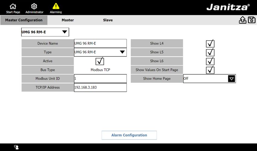
JPC 100-WEB                                                                                www.janitza.de

                                                                 2. 2 Safety measures
                                   WARNING                       When operating electric devices, it is un-
              Electrical voltage!                                avoidable for certain parts of these devices
              Severe physical injury or death can result         to conduct hazardous voltage. Consequently,
              from dangerous voltages.                           severe bodily injury or material damage can
              Therefore please abide by the following:           occur if they are not handled properly.
               • Before making connections to the
                 device, ground the device by means of           2. 3 Qualified personnel
                 the ground wire connection, if present.         This device must be operated and main-
               • Hazardous voltages can be present in            tained exclusively by qualified personnel.
                 all circuitry parts that are connected to
                 the power supply.                               Skilled personnel are persons who, on the
               • There can still be hazardous voltages           basis of their relevant training and experi-
                 present in the device even after it has         ence, are capable of identifying risks and
                 been disconnected from the supply               avoiding possible hazards that the operation
                 voltage.                                        or maintenance of the device might cause.
               • Equip stranded conductors with wire
                 ferrules!
               • Only connect screw terminals with the                               WARNING
                 same number of poles and the same                Risk of injury due to improper use
                 type.                                            If the device is not operated in accordance
               • Switch off the installation before com-          with the documentation, protection is no
                 mencing work!                                    longer ensured and the device can be dan-
                                                                  gerous.

                              ATTENTION
              Material damage due to security vulnerabil-
              ities in programs, IT networks and proto-
              cols.
              Security vulnerabilities can lead to data misuse
              and faults and even the standstill of your IT
              infrastructure.
              To protect your IT system, network, data
              communications and measurement devic-
              es:
              · Inform your network administrator and/or
                IT representative.
              · Always keep the meter firmware up to
                date and protect the communication to
                the meter with an external firewall. Close
                unused ports.
              · Take protective measures against viruses
                and cyber attacks from the Internet, e.g.
                through firewall solutions, security up-
                dates and virus protection programs.
              · Close security vulnerabilities and update
                or renew existing protection for your IT
                infrastructure.

6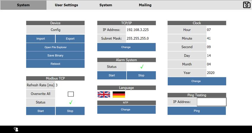
www.janitza.de JPC 100-WEB
3. Product description
3. 1 Scope of performance 3. 3 Incoming goods inspection
The device is intended for: The prerequisites for trouble-free and safe
operation of this device include proper trans-
• Visualization of current and voltage mea- port, storage, setup and assembly, as well as
suring devices in bus systems. proper operation and maintenance.
• Measured value monitoring of connected
Janitza measurement devices. Exercise due caution when unpacking and
• Configuration of connected slave devices. packing the device, do not use force and only
use suitable tools.
You can connect up to 3 Janitza master
devices and up to 30 Janitza slave devices to Check the devices for flawless mechanical
the JPC 100-WEB and manage them via the condition by visual inspection.
touchscreen. You can retrieve measured val-
ues from all integrated devices and configure Check the scope of delivery for complete-
slave devices. ness before you start installing the device.
The slave devices are integrated either via If it can be assumed that safe operation is no
the gateway function of the master de- longer possible, the device must be taken out
vices or directly via Modbus RTU with the of operation immediately and secured against
JPC 100-WEB as the master device. unintentional start-up. It can be assumed that
safe operation is no longer possible if the
device, for example:
ATTENTION
• has visible damages,
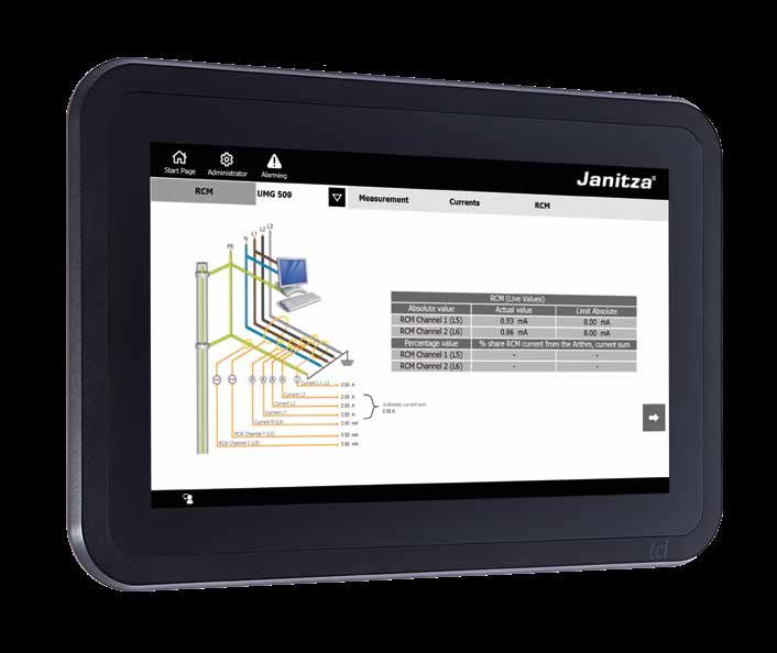
To be able to display the RCM values of the
• no longer functions despite an intact pow-
UMG509, the measurement device requires
er supply,
at least firmware 5.009.
• was subjected to extended periods of un-
favorable conditions (e.g. storage outside
3. 2 Operating concept of the permissible climate thresholds
You can operate the device in the following without adjustment to the room climate,
ways: condensation, etc.) or transport stress
(e.g. falling from an elevated position, even
• Directly on the device via the display with without visible external damage, etc.).
the touchscreen.
• Via the Ethernet interface with a connected 3. 4 Scope of delivery
PC.
Quantity Part. no. Designation
This operating manual only describes the
operation of the device via the touchscreen. 1 15.06.358 JPC 100-WEB
Installation instruc-
1 33.03.381 tions
1 Mounting kit
7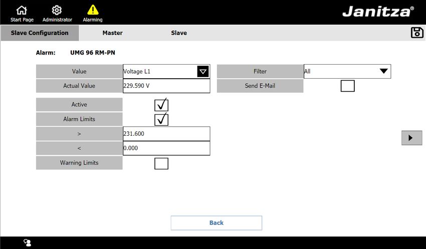
JPC 100-WEB www.janitza.de
3. 5 Intend use
The device is:
• Intended for installation in control cabinets.
• Not intended for installation in vehicles!
Use of the device in non-stationary equip-
ment constitutes an exceptional environ-
mental condition and is only permissible
by special agreement.
• Not intended for installation in environ-
ments with harmful oils, acids, gases,
vapors, dusts, radiation, etc.
3. 6 Supported measuring devices
The JPC 100-WEB supports the configurati-
on of the following measuring devices:
Measuring device Master device Slave device
UMG 96 RM-E
UMG 96-PA
UMG 604-PRO
UMG 605-PRO
UMG 509-PRO
UMG 512-PRO
UMG 20 CM
UMG 96 RM
UMG 96 RM-EL
UMG 96 RM-P
UMG 96 RM-PN
UMG 96 RM-CBM
UMG 103-CBM
Zähler MID B2x
Table of measuring devices supported by the JPC 100-WEB
8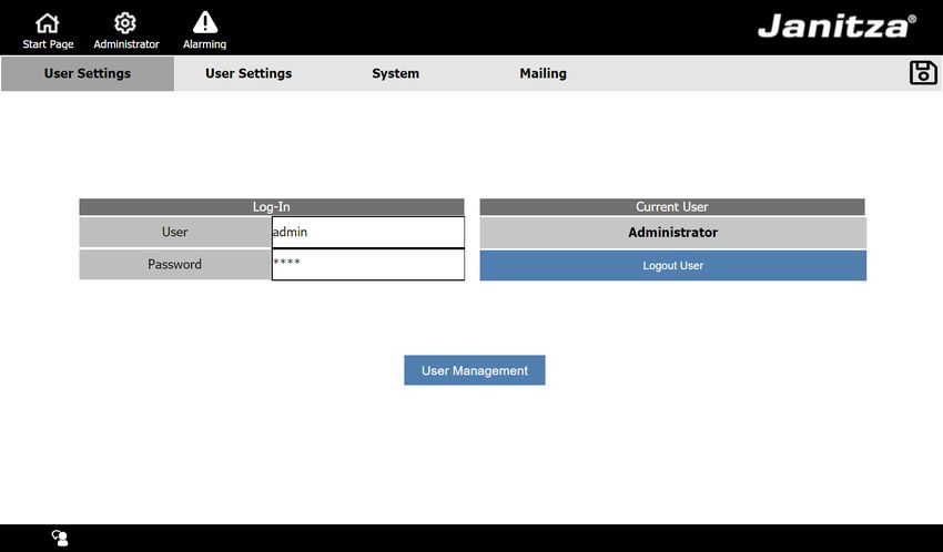
www.janitza.de   JPC 100-WEB

                         9
JPC 100-WEB www.janitza.de
4. Mounting
4. 2 Mounting orientation
WARNING The break-out dimension in the switchboard
Risk of injury due to electrical voltage! is 261 ± 1 mm x ±164 ± 1 mm (10.27 ± 0.04
Severe bodily injury or death can result in x 6.46 ± 0.04 in) with a wall thickness of
from: approximately 2 to 4 mm (0.08 bis 0.16 in).
• touching bare or stripped leads that are 261 ± 1
energized.
• device inputs that pose a hazard when
touched.
Therefore please abide by the following:
164 ± 1
• Disconnect your system from the pow-
er supply before starting work!
R15
CAUTION
Material damage due to disregard of the Fig.1: Mounting orientation of the JPC 100-WEB
installation instructions!
Disregard of the installation instructions can
damage or destroy your device.
Observe the information on the mounting
orientation in the sections "Mounting"
and "Technical Data".
4. 1 Installation location
The device is suitable for installation in
stationary and weatherproof switchboards
indoors.
10www.janitza.de JPC 100-WEB
4. 3 Securing 5. Secure the retaining brackets by tighten-
The device must be mounted on a flat, clean ing the fastening screws.
and burr-free surface by means of the retain-
ing brackets (Fig.2) included in delivery. Un-
evenness can lead to damage of the display
and to the entry of dust and water.
Fig.6: Securing the retaining brackets
Fig.2: Rear view with retaining brackets
1. Place the device into the prepared instal-
lation cutout from the front.
2. Insert the retaining brackets into the
openings on the device provided for this
purpose.
Fig.3: Inserting the retaining brackets
3. Push the retaining brackets towards the
back until they are flush with the back of
the opening.
Fig.4: Pushing the retaining brackets towards the back
4. Insert the fastening screws included in
delivery into the retaining brackets.
Fig.5: Inserting the fastening screws
11JPC 100-WEB www.janitza.de
5. Installation
5. 3 Connection to a master device
WARNING The JPC 100-WEB is connected to the gate-
Risk of injury due to electrical voltage! way devices / master devices of up to three
Severe bodily injury or death can result bus systems via Ethernet:
from: JPC 100-WEB
• Touching bare or stripped leads that are
energized.
• device inputs that pose a hazard when
touched.
Therefore please abide by the following:
Ethernet Ethernet
• Disconnect your system from the pow-
er supply before starting work!
UMG 605-PRO
as master
Slave 1 Slave 2 Slave n
5. 1 Circuit breaker
When installing the device in a building, pro-
vide a suitable circuit breaker for the supply
voltage in order to disconnect the device
Modbus Modbus Modbus
from the power supply.
Fig.7: Bus topology with a UMG 605 as master and
• Install the circuit breaker near the device JPC 100-WEB connected
and within easy reach of the user.
• Mark the circuit breaker as the disconnect-
ing device for this measuring device. 5. 4 Connection as a master device
In addition, the JPC 100-WEB is itself able to
5. 2 Supply voltage function as a master in a bus system via the
A supply voltage is required to operate the RS485 interface.
device. Please refer to the technical data for
the type and level of supply voltage for your JPC 100-WEB as master
device.
Slave 1 Slave 2 Slave n
The following power supply options are
available:
Modbus RTU Modbus RTU Modbus RTU
• 12 V via jack connection
• 24 V via plug-in terminals Fig.8: Bus topology with the JPC 100-WEB as the master
Before applying the supply voltage, make
sure that the supply voltage corresponds to
the specification in the technical data. (see
section 11. on page 30)
If no indication appears on the display after
connecting the supply voltage, check wheth-
er the supply voltage is within the nominal
voltage range.
12www.janitza.de JPC 100-WEB
6. Introduction to operation
To access the measurement devices via The JPC 100-WEB user interface is divided
the user interface, they must be connected into three menus: Start Page, Settings and
(described in 5. on page 12) and integrated Alarming. These can be called up via the
(described in 9. 1. on page 24 and 9. 2. on corresponding button in the menu bar ( 2 ).
page 26).
1 2
3 4
5
Fig. 09: Start page
1 Settings menu (depending on the user role, this menu is labeled Administrator, Read only
or Operator)
2 Menu bar
3 Selected master device
4 Measured value overview of the selected master device
5 Overview of slave devices
13JPC 100-WEB www.janitza.de
6. 1 Start page 6. 3 Log in
The start page (Fig. 09) shows an overview Log in to the interface to make changes to
of all integrated devices that is structured as the system settings and the configuration of
follows: the devices and alarms.
• Overview of the master devices in the Open the log-in window via the Settings (Fig.
upper area. Optionally, a measured value 09 1 ) and then the User settings tab.
overview of the selected master device is
displayed at this location. Once you have entered valid login data in the
• Tabular measured value overview of the login window, you are automatically logged in
slave devices assigned to the selected to the interface.
master device in the lower area.
For more information, see 7. 2 Users (login to
the system) on page 19.
Select the respective master device using the names of the master devic-
es.
Use the Measurement -Details/Details buttons to retrieve further mea-
sured values of the respective device (the measured values displayed de-
pend on the device type). For master devices you can hide the measured
value overview on the start page using the configuration options.
Open the configuration menu of the selected master device with the Con-
figuration button.
6. 2 Remote access
To access JPC 100-WEB from a PC via the
Ethernet connection, proceed as follows:
1. Open a browser on the PC.
2. Enter the following in the ad-
dress line: http://[IP address of the
JPC 100-WEB]:8080/jpc.html
For an explanation of how to determine the IP
address of your JPC 100-WEB, see section
7. 1. 3.
14www.janitza.de JPC 100-WEB
7. Settings
7. 1 System
Use the System tab to configure the basic
settings of the JPC 100-WEB such as inter-
faces, time setting or language. The menu is
divided into the areas Device, Modbus, TCP/
IP, Alarm System, Language, Clock and Ping
testing.
You can access the system settings via the
Settings menu and then the System tab.
1 2
3
Fig. 10: System settings
1 Currently selected tab
2 Tab overview for settings menus
3 System settings with areas
15JPC 100-WEB www.janitza.de
7. 1. 1 Device
3. Navigate to the storage location of the
The Device area provides you with the option configuration file.
of importing/exporting the settings and of 4. Touch the configuration file until the con-
restarting the device. text menu opens.
5. Select the option Copy.
6. Navigate to the desired storage location
on the external storage medium.
7. Paste the file here using the Editor ( 2 ).
2
Importing configuration
To import a configuration file, it must be avail-
1
able on a USB flash drive.
1. Connect the USB flash drive to the
USB 2.0 interface of the JPC 100-WEB.
2. Use the System Settings to open the file
explorer.
3. Navigate to the storage location of the
configuration file on the storage medium.
4. Copy the configuration file (described in
3
section „Exporting configuration“.)
Fig. 11: File system 5. Navigate to the folder Internal Memory/
Download/WWW/Jpc100Cfg.
Exporting configuration 6. Paste the file here using the Editor.
You can export the settings of the JPC 7. Return to the system settings using the
including all device configurations. This can Back ( 3 ) button.
be useful to create a backup of the settings
or to transfer the configurations to other
JPC 100-WEB devices.
Use the Export button to save the config-
uration file of the JPC 100-WEB in the file
system. The storage location is displayed in
the subsequent pop-up window.
Fig. 12: The "Export device configuration” pop-up window
Proceed as follows to transfer the configura-
tion file to an external storage medium:
1. Connect a suitable, external storage
medium to the USB 2.0 interface of the
JPC 100-WEB.
2. Use the Open File Explorer (Fig. 10) but-
ton to open the file system.
16www.janitza.de JPC 100-WEB
7. 1. 2 Modbus TCP Changing IP-settings
The Modbus TCP area displays the sampling
rate (refresh rate) at which the JPC 100-WEB 1. Open the hardware settings by pressing
queries the measured values of the connect- the Change button.
ed bus systems. 2. Open the Ethernet settings in the Wire-
less & Networks area.
The number of meters connected influences
the Refresh Rate. You can activate/deactivate the interface
using the Ethernet toggle button.
Use the Overwrite All checkbox to enable the
overwriting of the device configurations of all Pressing the Ethernet Ip mode entry switches
connected slave devices. The configuration is the setting between DHCP and static (fixed
only transferred if this function and the Mod- IP address).
bus communication are activated.
Use the Back button (Fig. 11 3 ) to return to
the system settings.
Fig. 13: Modbus TCP settings
7. 1. 3 TCP/IP Fig. 14: Ethernet settings
The TCP/IP area shows the current IP ad-
dress and subnet mask of the JPC 100-WEB.
ATTENTION
Material damage due to incorrect net-
work settings.
Incorrect network settings can cause faults
in the IT network.
Consult your network administrator for
the correct network settings for your
device.
Fig. 15: TCP/IP settings
DHCP is active ex works, which means the
device is assigned an IP address dynamically
when it is connected to a network.
17JPC 100-WEB www.janitza.de
7. 1. 4 NTP / Clock
The time for the JPC 100-WEB is either set
manually or obtained from an NTP server.
NTP stands for Network Time Protocol which
is a protocol for time synchronization of de-
vices in a network.
Fig. 19: Change the time and date settings
Fig. 16: Change the NTP settings
7. 1. 5 Ping testing
Fig. 18: Ping testing
In the Ping testing area, you can ping an
IP address to test if the JPC 100-WEB has
access to it.
To do so, enter the IP address in the text field
and then click the Ping button.
The test may take a few seconds.
Fig. 17: Time and date settings
Changing settings
Press the Change button in the NTP or Clock
area to open the time settings (Fig. 19).
Here you can perform the following actions
by touching the corresponding entry:
• Select between automatic and manual
time and date setting.
• Select between automatic and manual
time zone.
• Change the NTP server.
• Change the time format (12h/24h)
18www.janitza.de JPC 100-WEB
7. 2 Users (login to the system)
Use the User Settings tab to log in/out on the
system or to change the user.
Fig. 20: User Settings
When operating the JPC 100-WEB, the NOTE
actions which are possible differ according to Change the password as soon as you start
the active user role. working with JPC 100-WEB. Remember the
new password.
The JPC 100-WEB includes the following
user roles:
• Read only: Is active as long as the user
is not logged in. This role allows viewing
of measured values, system settings and
alarms.
• Operator: Standard role for logged in
users. They can also acknowledge and
configure alarms and warnings as well as
configure devices.
• Administrator: Can additionally manage
other users, change the administration
password and change system settings.
An administrator user is available to you with
following login data:
• Username: admin
• Password: 1234
19JPC 100-WEB www.janitza.de
7. 2. 1 User management
The following actions are available in the user To change the username or password, touch
management: the appropriate field of the table.
• Add, delete or edit users. All users that have been created are dis-
• Change the administrator password. played in a table. Five lines of the table are
displayed per page. Use the arrow buttons
To access the user management, you need on the right side of the table to scroll through
administrator rights. the table pages.
You can open the user management via
the User Management button on the User
settings tab. In this case a new login with
administrator access data is necessary.
Fig. 21: User Management
20www.janitza.de JPC 100-WEB
7. 3 Emailing
In addition to the alarms and warnings (sec-
tion 8. on page 22) on the user interface,
the JPC 100-WEB can also send notifications
by email.
Fig.22: Email settings
The JPC 100-WEB requires access to a
SMTP server to be able to send e-mails.
You must define an interval at which
JPC 100-WEB checks whether new warnings
or alarms are present. All new, unacknowl-
edged warnings and alarms are collected in
an email and sent to the specified recipient.
Ask your system administrator for information
about the Host IP, Encryption, Port and mail
server access data.
21JPC 100-WEB www.janitza.de
8. Alarming
Fig. 23: List of the current alarms
You can use the JPC 100-WEB to configure Alarm/warning threshold is
warnings and alarms for the measured values currently over/undershot
of the connected master and slave devices
Alarm/warning threshold is currently
(section 9. 3. on page 28). no longer over/undershot
All warnings and alarms are displayed in the Alarm has been acknowledged
alarm list found in the Alarming menu.
Current alarms must be acknowledged. You Alarm has not yet been acknowledged
can either acknowledge all alarms at once by
pressing the Acknowledge All button or ac- Fig. 24: Alarm status symbol explanation
knowledge individual alarms by pressing the
check mark after the corresponding alarm.
Use the Historic Alarms button to open a list
of all alarms that are no longer current and
have been acknowledged.
The Status column shows you the status of
the corresponding alarm at a glance.
22www.janitza.de JPC 100-WEB
9. Configuration
Fig. 25: Configuration
Use the configuration to integrate new mea-
surement devices in the JPC 100-WEB and
to configure integrated devices.
Call: Start page > Configuration.
You must be logged in to the device as an
administrator to configure measurement
devices.
Use the tabs Master and Slave to switch be-
tween the configuration of master and slave
devices.
23JPC 100-WEB www.janitza.de
9. 1 Master devices
The JPC 100-WEB allows you to manage
up to four master devices. The first position
is reserved for the JPC 100-WEB (for more
information, see „9. 1. 1 Integrating a new
master device“).
To configure a device that is already integrat-
ed, select it on the start page before opening
the configuration.
Different configuration options are available
here depending on the type of the selected
device.
Use this drop-down menu to select which device
you are configuring in the JPC 100-WEB. The first
list entry of the master devices is reserved for the
JPC 100-WEB as the master.
The device name determines the name under
which the device is listed in the JPC 100-WEB
user interface. The configuration on the device
itself is not affected by this.
This checkbox controls the visibility of the device
on the start page.
When you integrate measurement devices using
Modbus RTU, the master device (JPC 100-WEB)
and slave devices must have the same baud rate.
(The respective user information describes how
to determine the baud rate of the respective slave
devices.)
If you integrate master devices using Modbus TCP,
you must know the Modbus ID and the TCP/IP ad-
dress of the device. (Information on how to deter-
mine this data can be found in the corresponding
usage information.)
Use these checkboxes to specify whether and
which values of the master device are displayed on
the start page. The values available here depend
on which measured values are supplied by the
device.
For devices with a device homepage (e.g. UMG
509/512/604/605), you can optionally display a
button in the measured value details which leads
to the device homepage.
Use the Actions for all UMGs button to reset ener-
gy meters and minimum/maximum current mea-
surement values for all UMGs and to transfer the
current configuration to all UMGs
Save your changes using the Save button.
Use this button to open the alarm configuration for
this device.
24www.janitza.de JPC 100-WEB
9. 1. 1 Integrating a new master device 9. 1. 2 Using the JPC 100-WEB as a mas-
To integrate a new master device into the ter device
JPC 100-WEB interface, proceed as follows: You can use the JPC 100-WEB itself as a
master device by means of the built-in RS-
1. Make sure that the JPC 100-WEB is con- 485 interface.
nected to the master device via Ethernet.
2. Open the device configuration using the 1. Open the master device configuration.
button on the start page. 2. Select the first option from the drop-
3. In the drop-down menu, select under down menu.
which of the four available master de- 3. Activate the master device via the check-
vices the new device should be stored. box.
(The first position is reserved for the 4. Select the baud rate used in the bus from
JPC 100-WEB as the master.) the drop-down list.
4. Configure the name and communication 5. Save the configuration.
settings (TCP/IP and Modbus).
5. Optional: Use the checkboxes (see page The master device is now displayed on the
24) to configure which measured val- start page. To learn how to integrate slave
ues are displayed on the start page. devices connected to the JPC 100-WEB,
6. Optional: Activate/deactivate the link to see 9. 2. 1 Integrating a new slave device on
the device homepage in the measured page 27
value details. (Only for measurement
devices with a device homepage.)
7. Save the configuration.
The master device is now displayed on the
start page. To learn how to integrate slave
devices connected to the JPC 100-WEB, see
9. 2. 1. on page 27
25JPC 100-WEB www.janitza.de
9. 2 Slave devices
3 4
5
1
2
Fig. 26: Slave configuration using the example of the UMG 20 CM
1 Configuration on the JPC 100-WEB 3 Actions for all UMGs
2 Configuration on the measurement device 4 Save configuration
5 Actions for this UMG
In addition to the display settings ( 1 ), there are also configuration options available for slave
devices on the slave device itself ( 2 ). These depend on the respective slave device.
As an example the configuration options for the UMG 20 CM slave device are explained be-
low.
Use this drop-down menu to select which slave
device you want to configure in the JPC 100-WEB.
You can switch between the different measure-
ment channels of the UMG 20 CM quickly using
the arrow buttons.
Use this drop-down menu to assign the slave de-
vice to the master device via which it is connected.
Use this checkbox to define whether the device
measures operating current or residual current
(RCM).
Use this checkbox to activate the low-pass filter
for the residual current measurement
The digital outputs of the measurement device can
be set if the warning (output 1) or alarm (output 2)
threshold is exceeded.
You can define an overcurrent warning and alarm
threshold for each channel.
26www.janitza.de JPC 100-WEB
Use the response delay to define how long the
overcurrent warning or alarm threshold must be
exceeded for a warning or alarm to be triggered.
Use the Actions for all UMGs button to reset ener-
gy meters and minimum/maximum current mea-
surement values for all UMGs and to transfer the
current configuration to all UMGs.
Use the Actions for this UMG button to reset ener-
gy meters and minimum/maximum current mea-
surement values for this UMG or this channel and
to transfer the current configuration to all channels
of the device.
You can configure alarms and warnings for both
slave and master devices („8. Alarming“)
Use the arrow buttons to switch between the indi-
vidual slave devices.
Fig. 27: Configuration options for the UMG 20 CM
9. 2. 1 Integrating a new slave device 9. 2. 2 Configuring the UMG 20 CM
To retrieve measured values from a connect- The available configuration options depend
ed slave device and to configure the device on the respective slave device type.
requires that it be integrated.
1. Open the configuration as described in
1. Make sure that the corresponding slave „Configuration“ on page 23.
device is connected either via a master 2. Use the tabs to go to the configuration
device or directly with the JPC 100-WEB. menu for slave devices.
2. Select the slave device you want to edit 3. Select the slave device you want to edit
using the drop-down menu. via the drop-down menu.
3. Select the type of the device to be inte- 4. Select the measurement channel to be
grated. configured.
4. Enter the Modbus address of the slave 5. Make the desired configurations on the
device. (Refer to the user manual of the device (for more information on configu-
device to find out how to determine this.) ration of the UMG 20 CM, please see the
5. Use the Belongs to master drop-down usage information).
menu to select to which master device 6. If desired, transfer the configurations to
the slave device is assigned. all channels of this slave device using the
6. Save the settings with the Save button. Actions for this UMG button.
7. Save the configurations using the Save
The device has now been integrated and can button.
be seen on the start page under the corre- 8. Use the menu bar to go to the settings
sponding master device. (Fig. 09 1 ).
9. Activate the function Overwrite all.
10. Start the Modbus communication.
27JPC 100-WEB www.janitza.de
9. 3 Alarms and warnings
Fig. 28: Alarm configuration of a master device
The alarm configuration of an integrated de-
vice can be opened via the Configuration.
Use the drop-down menu to select which mea-
sured value is to be monitored.
Here you can configure the upper (>) and lower (www.janitza.de JPC 100-WEB
10. Service and maintenance
The device is subjected to various safety 10. 2 Repairs and calibration
tests prior to outbound delivery. If a device is Repairs and calibration can only be carried
opened, the safety tests must be repeated. out by the manufacturer.
A warranty is only assumed for unopened
devices. 10. 3 Front panel foil
The front panel foil can be cleaned with a
10. 1 Remote access via TeamViewer soft cloth and standard household cleaning
To access the device via TeamViewer, start agents. Acids and acidic agents must not be
the TeamViewer Host application included in used for cleaning.
delivery:
10. 4 Disposal
1. Open the system settings. Please abide by national regulations! Dispose
2. Open the hardware settings with the of individual parts, as applicable, depending
Change button in the TCP/IP area. on their composition and existing coun-
3. In the Device area, open the Home menu try-specific regulations, e.g. as:
4. Select the Launcher 3 option.
5. Press the Home button. • Electronic waste
6. Open the menu ( ). • Plastics
• Metals
or engage a certified disposal
company to handle scrapping.
10. 5 Service
If questions arise that are not described in
this manual, please contact the manufacturer
directly.
7. Open the TeamViewer Host application.
The following information is essential for us
to be able to answer any questions you may
have:
• Device designation (see rating plate)
• Software release (see system display)
• Supply voltage
• An exact error description.
29JPC 100-WEB www.janitza.de
11. Technical data
General
Net weight approx. 900 g (2 lb)
Dimensions 282 mm x 184 mm x 35 mm (11.10 in x 7.24 in x 1.38 in)
Backlight (LED) Brightness: typ. 450 cd/m2 (41.8 cd/ft2)
Chip Rockchip RK3288 Quad-Core CPU 1.6 GHz
Main memory 2 GB DDR3 SDRAM
Memory capacity 8 GB eMMC
Cutout dimensions 261 ± 1 mm x 164 ± 1 mm (10.27 ± 0.04 in x 6.46 ± 0.04 in)
Interfaces
USB • USB 2.0 type A
• Micro USB
Ethernet • 1x RJ45
• Transmission rate 10/100 Mbit/s
RS-485 • Protocol: Modbus RTU/master
• 3-lead connection with GND, B, A
• Transmission rate1): 9.6 kbps, 19.2 kbps, 38.4 kbps, 57.6 kbps,
115.2 kbps, 230.4 kbps
Display
Type TFT color
Diagonal 10”
Resolution 1024 x 600 pixels
Touchscreen Capacitive multi-touch
Electrical properties
Supply voltage • 24 V DC (via terminal connection)
• 12 V DC (via jack connection)
Power consumption max. 13 W
Environmental conditions
Protection level to EN 60529 IP53 on the front, IP20 on the back
Operating temperature 0 to 35 °C (32 °F to 95 °F)
Storage and transport temperature 0 to 70 °C (32 °F to 158 °F)
Air humidity 10 to 90%, non condensing
1) Ensure a uniform baud rate in the bus system.
30www.janitza.de JPC 100-WEB
11. 1 Dimensional drawings
35 mm /
1.38 in
Fig. 29: Front view
282 mm / 11.10 in
Fig. 31: Side view
70 mm / 2.76 in
184 mm / 7.24 in
Fig. 30: Rear view
70 mm /
2.76 in
1 2 3 4 5 6
+- C B A
Fig. 32: Bottom view
1 Ethernet 4 24 V supply voltage (terminal connection)
2 USB 2.0 type A 5 RS-485 (3-pole)
3 Micro USB 6 12 V supply voltage (jack connection)
31Janitza electronics GmbH
Vor dem Polstück 6
D-35633 Lahnau
Tel.: +49 6441 - 9642-0
Fax: +49 6441 - 9642-30
email: info@janitza.de
www.janitza.com
Dok.-nr. 2.100.045.1.c | Status 09/2021 | Technical changes reserved.
You can find the latest status of the document in the download area at www.janitza.com.You can also read