Two Novel Multiband Centimetre-Wave Patch Antennas for a Novel OFDM Based RFID System
←
→
Page content transcription
If your browser does not render page correctly, please read the page content below
Journal of Communications Vol. 13, No. 6, June 2018
Two Novel Multiband Centimetre-Wave Patch Antennas
for a Novel OFDM Based RFID System
Nayan Sarker1, Md. Aminul Islam2, and M. Rubaiyat Hossain Mondal1
1
Institute of Information and Communication Technology (IICT), Bangladesh University of Engineering and
Technology (BUET), Dhaka-1000, Bangladesh
2
Department of Electrical, Electronic and Communication Engineering (EECE),
Military Institute of Science and Technology (MIST), Mirpur Cantonment, Dhaka-1216, Bangladesh
Email: nayan_ece09@yahoo.com; aminul9274@gmail.com; rubaiyat97@yahoo.com
Abstract—Two novel multiband patch antennas operating at telemedicine and transportation logistic [1]-[3]. RFID
centimetre band are proposed for a novel orthogonal frequency also has potential applications in museums, art galleries,
division multiplexing (OFDM) based radio-frequency hospitals, and military. Various frequency bands are used
identification (RFID) reader. Here, the first one is a dual band worldwide for RFID such as High Frequency (HF),
antenna with centre frequencies of 7.30 GHz and 9.50 GHz,
Ultrahigh Frequency (UHF), Super High Frequency (SHF)
while the second one is a triple band antenna centred at 7.75
GHz, 9.70 GHz and 11.90 GHz. Both the patch antennas are
also known as centimetre wave band (3 GHz – 30 GHz),
designed with equal-width horizontal arms as radiating elements and millimetre wave band. Usually the design of the
and a microstrip feeding line as the feeder. The antennas are RFID antenna in any frequency band is a complex task.
moderately small sized with dimensions of 40.30 mm by 35.10 Because of wireless spectrum crunch, researchers are
mm. Simulations with Computer Simulation Technology (CST) exploiting unused high frequencies in the centimetre band.
Microwave Studio tool indicate that competitive values of Different countries of the world apply different
different antenna parameters are achieved when compared with frequencies for RFID communication. Moreover,
centimetre band antennas described in the literature. With the different application scenarios within a country require
use of MATLAB tool, the bit error rate (BER) performance of
different frequencies. So, there is a need of designing a
the multiband antennas are simulated for outdoor Rayleigh and
Rician fading channels. Simulation results for the proposed two
single antenna having multiple resonance frequencies.
antennas indicate that for a given number of OFDM subcarriers, For instance, having a dual band and triple band antenna
the larger the bandwidth of the signals received by the RFID allows these to be used in two or three different types of
reader, larger the BER degradation. These results have wireless application scenarios, respectively [4], [5].
confirmed the usability of the designed antenna in commercial An RFID signal in the outdoor environment may
OFDM based RFID readers. experience multipath fading or distortion. In the case of
Index Terms—Bandwidth, Bit Error Rate (BER), centimetre- outdoor scenarios, Rayleigh or Rician fading and Doppler
wave, multipath fading, Orthogonal Frequency Division spread occurs [6]-[8]. These impairments cause inter
Multiplexing (OFDM), patch antenna, Radio Frequency symbol interference (ISI) as well as Inter Carrier
Identification (RFID). Interference (ICI). Therefore, in the presence of these
impairments, the overall bit error rate (BER) increases
I. INTRODUCTION and the reading range suffers. Similar to 4G cellular
In recent years, radio-frequency identification (RFID) communication scenarios, Orthogonal Frequency
has become a promising technology in the field of object Division Multiplexing (OFDM) encoding technique may
identification. A typical RFID system consists of a reader, be used to combat multipath effects in outdoor RFID
a reader antenna, a host computer, middleware software systems [9]-[14].
for the computer, and tags attached on items. RFID uses A number of research papers [15]-[22] report RFID
electromagnetic fields to identify and track tags that store systems where antennas operate in centimetre band.
electronic information about objects they are attached to. Furthermore, a number of antennas [23]-[27] studied for
RFID can read objects at a range up to 100 metres, can wireless applications can be adapted for RFID
read considerable number of information at a time and applications. One example of antenna designs for RFID
can be usable for both outdoor and indoor environment. applications is the work in [21] presenting an elliptical
Unlike optical barcode systems, no-line-of sight (NLOS) patch textile antenna at 2.45 GHz. A dual band tag
communication is possible by RFID systems. RFID has antenna at 2.45 GHz and 5.8 GHz is proposed in [22]. A
several applications including library management, cattle compact dual band antenna operating around the range of
identification, toll collection, flood level detection, 2.4 GHz and 5.0 GHz is proposed for RFID systems in
parking access control, security, retail stock management, [18], [20]. The authors of [17] describe a dual band
antenna at resonance frequencies of 2.44 GHz and 5.77
GHz, and a triple band antenna at resonance frequencies
Manuscript received January 27, 2018; revised May 18, 2018. of 2.44 GHz, 3.55 GHz and 5.79 GHz. Similarly, the
Corresponding author email: nayan_ece09@yahoo.com.
doi:10.12720/jcm.13.6.303-316
authors of [19] present high bandwidth high gain dual
©2018 Journal of Communications 303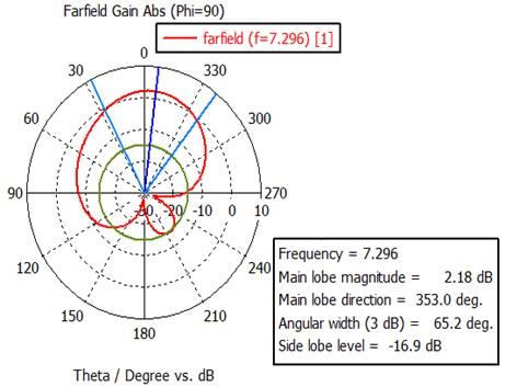
Journal of Communications Vol. 13, No. 6, June 2018

band and triple band antennas at 2.4 GHz and 5.8 GHz                  tags, antennas (both for reader and tag), a RFID
bands. Different designs of 10 GHz antennas are                       middleware and destination host PC or a monitoring
proposed for RFID scheme by the authors of [15].                      system. Generally, the RFID reader is known as
Furthermore, a quasi-isotropic antenna at 10.5 GHz is                 interrogator that acts as a Radio Frequency (RF)
devised for RFID tags in [16]. However, none of these                 transceiver. The RFID reader system is controlled by a
works evaluate the BER performance of the RFID                        Digital Signal Processor (DSP) or a microprocessor. The
systems. Only the concept of OFDM based RFID system                   RFID tag contains an Integrated Circuit (IC) commonly
is proposed in [28]. However, a detail investigation of               known as microchip associated with an antenna. The tag
OFDM based RFID scheme and the evaluation of BER is                   is placed to an object to identify. Tags can be classified
yet to be done. In this paper, we focus on an OFDM                    into two major categories depending on tag on board
based outdoor RFID system operating in the centimetre                 power supply which are active or passive tag [29]. If the
band. The contributions of this paper can be summarized               tag has on board power supply then it is called active tag,
as follows:                                                           otherwise it is called passive. Based on the Application
    1) A dual band and a triple band antenna are                      Specific Integrated Circuits (ASIC) in tag (transponder)
        proposed centred around 8 GHz - 12 GHz for                    section, RFID systems can be categorized as chip based
        RFID reader section. This new multiband design                and chip less RFID.
        is adapted from the design of a single band 10                   First of all, the RFID reader antenna transmits energy
        GHz antenna described in [15].                                signal as well as clock signal to the tag system. The tag
    2) Based on the bandwidths of the proposed new                    antenna receives energy signal to power up the tag
        antennas, the BER performance of the RFID                     microchip. Then reader sends data signal to the tag. The
        communication system is evaluated for the case                tag antenna receives the reader signal and processes it.
        where the transmitted signal bandwidth is equal
                                                                      After processing, the tag microchip retransmits a
        to the reader antenna bandwidth.
    3) Comparisons are made between the proposed                      backscatter signal associated with data signal to the
        RFID antennas and the relevant antennas                       reader. The backscatter signal is more strengthen if tag
        described in the literature.                                  antenna’s inductive impedance is perfectly matched with
   The rest of the paper is organized as follows. In                  tag microchip capacitive impedance. Finally, the reader
Section II, an OFDM based RFID system is described.                   decodes tag backscatter signal and sends it to the
The design of a dual and a triple band antenna is                     destination host or central monitoring system via RFID
introduced in Section III. Simulation results on the                  middleware. It is notable that the read range of RFID
bandwidths, gain, directivity, radiation efficiency, etc. for         system depends on several parameters such as either the
both antennas are presented in Section IV. Next, Section              tag is active or passive, reader and tag antenna gain,
V presents the BER performance using designed antenna                 directivity, obstacles between reader and tag and the
bandwidth, where the effects of fading channel (Rayleigh              wireless channel overall. It has already been mentioned
and Rician) are studied. In addition, a comparative study             that in a practical outdoor wireless channel, multipath
between dual and triple band antennas with various                    fading causes inter symbol and inter carrier interference
reference antennas is discussed in Section VI. Finally,               to degrade the system performance. The use of OFDM
Section VII provides concluding remarks.                              waveform can combat this effect. Therefore, OFDM
                                                                      transmitter can be used at the tag section and OFDM
     II.   OFDM BASED RFID SYSTEM DESCRIPTION                         receiver at the reader section. In the following, the
  The block diagram of a complete RFID                                OFDM transmitter and receiver useful in outdoor RFID
communication system is shown in Fig. 1. The main                     system are described.
components of a RFID system are a RFID reader, RFID

Fig. 1. Block diagram of an OFDM based RFID system.

©2018 Journal of Communications                                 304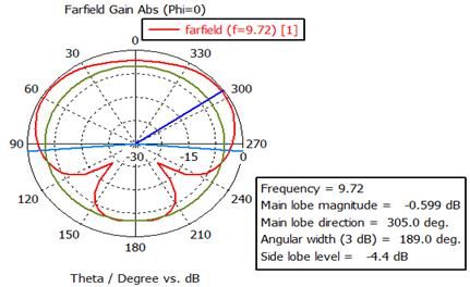
Journal of Communications Vol. 13, No. 6, June 2018
Fig. 2. Block diagram of an OFDM transmitter and receiver.
Fig. 2 shows the typical block diagram of an OFDM At the OFDM receiver, the received signal is first
transmitter and receiver system [9]-[13]. At the OFDM down converted to base band signal. The base band signal
transmitter, channel coding and interleaving are is then converted to discrete signals by passing through a
performed. High speed serial data streams are then LPF and Analog to Digital Converter (ADC). The
mapped onto complex numbers from the constellation received discrete base band time domain signal is fed to
being used such as M-array pulse amplitude modulation an N -point FFT block after the removal of CP and the
(M-PAM), M-array quadrature amplitude modulation (M- S/P conversion. The FFT output is described by the given
QAM) or M-array phase shift keying (M-PSK). The equation
complex constellations are converted into N number of
1 N /2
j 2 kt
lower speed parallel data streams using serial to parallel Xk
N
x(t ) exp(
T
)
(S/P) conversion block. These parallel data streams are t 1 N / 2
converted into time domain complex numbers from the
frequency domain using N -point Inverse Fast Fourier for 1 N 2 ≤ t t ≤ N 2 (2)
Transform (IFFT) block. The complex time domain After that the FFT output is equalized to obtain the
samples at the output of the IFFT are given by following desired frequency domain signal by a single tap zero
expression forcing equalizer. Finally, the original information is
recovered by channel decoding and de-interleaving using
1 N /2
j 2 tk
x(t )
N
N
X k exp(
T
) the demodulation block [9]-[13].
k 1
2
III. ESIGN OF TWO ANTENNAS IN CENTIMETRE BAND
for 1 N 2 ≤ k ≤ N 2 (1) Both the antennas are designed based on a single band
microstrip antenna shown in [15]. Computer Simulation
where k is the subcarrier index, T is the symbol period Technology (CST) Microwave Studio is used for antenna
before adding cyclic extensions, and the smaller case simulation and optimization. Commercially available
letters denote time domain and the upper-case letters Rogers RT5880 substrate with permittivity, r = 2.2, loss
denote frequency domain samples. After converting the
tangent, tan = 0.0009, substrate thickness, h = 0.787
parallel signals to serial sequence using parallel to serial
(P/S) converter at the output of the IFFT, a cyclic mm, and copper thickness, t = 0.018 mm is used for the
extension known as Cyclic Prefix (CP) is added. By antenna design. The initial length and width of the two
adding a CP, the symbol period is increased which is antennas are obtained by taking 10 GHz resonance
higher than the delay spread (δ) and thus minimizes frequency. In order to obtain the dual band and the triple
multipath fading effects. A digital to analog converter band, the length and the width are adjusted to maximize
(DAC) is then used to convert the samples of this the antenna performance. The detail design procedure is
extended OFDM symbol to continuous time domain described in the next sections.
analog signals and filtered by a low pass filter (LPF) to A. Dual Band Antenna Design
avoid unwanted signal frequency and finally are up- Plan view and 3-D perspective view of the dual band
converted to the desired frequency before transmission centimetre wave microstrip patch antenna are shown in
[9]-[13]. Fig. 3. Here, the proposed dual band antenna is designed
©2018 Journal of Communications 305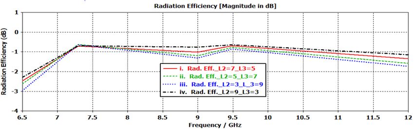
Journal of Communications Vol. 13, No. 6, June 2018
and optimized with resonance frequencies f r1 = 7.30 GHz optimized dimensional parameter values of the proposed
and f r 2 = 9.50 GHz on Rogers RT5880 substrate. The dual band antenna are shown in Table I.
Fig. 3. A 3-D and a 2-D view of dual band RFID reader antenna.
initially obtained using the procedure and expressions
TABLE I: SPECIFICATIONS OF DUAL BAND ANTENNA.
given in (3)-(4) [30]. In order to obtain the antenna’s
Antenna Parameters Length in mm higher order transverse electromagnetic modes (TEM)
Wg 40.29 whose attributes are very closely matched with the
fundamental mode, a technique is introduced to calculate
Lg 35.12 the proposed antenna’s length and width. This technique
is commonly known as size extension method [31].
W1 = W2 36.29 According to the size extension method, the extended
patch antenna width ‘W’ and length ‘L’ can be expressed
L3 5 as [31]:
L4 15.56 (2 N 1)
W ( ) (3)
6.56
2 r 1 / 2 2
L1
7 (2 N 1)
L2 L ( ) 2L (4)
eff 2
W3 (Width of L3 ) 7
where is the proposed antenna’s operating wavelength,
W4 (Width of L4 ) 3
r is the relative permittivity (dielectric constant) and N
is a positive valued integer number (in this antenna
Here, two horizontal metal plates denoted as Arm1 and design we assume N =1). Due to the fringing field effect,
Arm2 with the same width ( W1 = W2 =36.29 mm) are used the physical dimensions of the microstrip patch antenna
would look electrically wider. The extended length of the
as the main radiating element of the proposed dual band patch ∆L on each side is a function of antenna width to
antenna. The length of radiator arms Arm1 ( L1 ) and substrate height ratio ( W h ) and the effective dielectric
Arm2 ( L2 ) are 6.56 mm and 7 mm, respectively. A single constant eff [32]. So, ∆L and eff are obtained by the
microstrip feeding line is used to feed this antenna so that
following equations
it is comparable to an array of two extra wide microstrip
patch elements [15]. The width and the length of radiator ( eff 0.3)(0.264 W h)
L 0.412h (5)
that connects Arm1 and Arm2 is W3 =7 mm and L3 =5 ( eff 0.3)(0.8 W h)
mm, and the width and the length of the microstrip
feedline is W4 = 3 mm and L4 = 15.56 mm, respectively. where effective dielectric constant,
Finally, a copper ground is placed on the opposite side
r 1 r 1 h 12
of the antenna substrate to complete the design. The eff ( )(1 12 ) (6)
length of the radiator that connects Arm1 and Arm2 is 2 2 W
©2018 Journal of Communications 306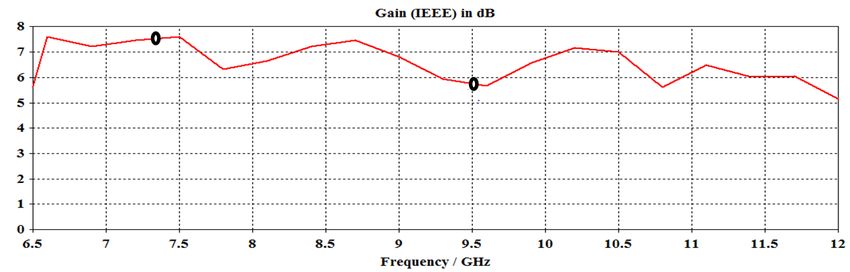
Journal of Communications Vol. 13, No. 6, June 2018
To feed the proposed antenna microstrip transmission respectively. Better antenna performances are achieved
line length, L4 = LT , and its input impedance Z in are by optimizing antenna’s various parameters using
optimization tools of CST Microwave Studio. The
obtained by the expression introduce in [23] optimized dimensional parameters of the triple band
0 antenna are shown in tabular form in Table II.
Zin 29.9 (7)
W TABLE II: SPECIFICATIONS OF TRIPLE BAND ANTENNA.
(2M 1) Antenna parameters Length in mm
LT ( ) (8) Wg 40.29
2 2 Lg 35.12
W1=W2=W3 36.30
where M is assumed as a positive valued integer number
L4=L5 5
(in the designed antenna M =1) and 0 is the operating L6 10.12
wavelength at free space in desired frequency. L1 3
The equations described above are used to design a L2=L3 5
W4 (Width of L4) 5
dual band (one band at frequency 7.30 GHz and other W5 (Width of L5) 8
band at 9.50 GHz) linearly polarized antenna. Initially the W6 (Width of L6) 4
transmission line length L4 and width W4 are obtained
using equations given in [30]. The ground plane width IV. SIMULATION RESULTS OF THE ANTENNA
and length ‘ Wg W 6h ’ and ‘ Lg L 6h ’ are initially PERFORMANCE
set respectively from the method described in [15]. For The simulation results of the optimized dual band and
better antenna performance, the length and width are triple band microstrip patch antennas (Fig. 4) for OFDM
adjusted using optimization tools of CST Microwave based RFID reader using CST Microwave Studio are
Studio. Using optimization tools of CST, the length of described in the next sections.
Arm2 is adjusted as L2 =7 mm, and the lengths of A. Simulation Results of the Optimized Dual Band
connector Arm1 and Arm2 are adjusted to L3 = 5 mm. Antenna
Desired impedance matching, acceptable gain, directivity, The simulation results of the proposed dual band
resonance frequency at centimetre band, S11 parameters, antenna using waveguide ports are at resonance
frequencies f r1 = 7.30 GHz and f r 2 = 9.50 GHz are
Lowest Side Lobe Level (LSLL), radiation efficiency are
achieved by final optimization using CST of the proposed presented in this section. The simulated return loss at
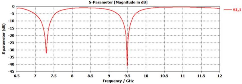
dual band antenna for RFID reader applications. f r1 is 32.25 dB and at f r 2 is 41.0 dB, which are shown
in Fig. 5. This indicates antenna impedance is
B. Triple Band Antenna Design
considerably matched with the waveguide port
By modifying the dual band antenna structure impedance as less amount of power is reflected back from
described in the previous section, a novel triple band the input terminal of the antenna.
antenna at centimetre band is designed in this section.
Plan view of the triple band antenna design is shown in
[33]. The design mechanism of the proposed triple band
antenna at centimetre band with three resonance
frequencies is almost similar to the dual band antenna
which is described in Section III.A. The main difference
between the proposed dual band and the triple band
antenna is the number of horizontal arms as well as the
variation in length of the horizontal arms. The length and
the width of various radiator elements of triple band
antenna are obtained by the same equations that are
described in Section III. Three horizontal metal plates
denoted as Arm1, Arm2, and Arm3 with the same width
( W1 = W2 = W3 = 36.30 mm) are used as the main radiator
element of this proposed antenna. The lengths of Arm2 Fig. 4. Triple band RFID reader antenna.
and Arm3 are the same, L2 = L3 = 5 mm, and the length of
Fig. 5 and Fig. 7 show the simulated E-plane (φ=00)
Amr1 is L1 = 3 mm. and H-plane ((φ=900) far field radiation patterns at
A single microstrip feeding line is used to feed this f r1 and f r 2 , respectively indicating side lobe level, 3 dB
antenna so that it is comparable to an array of three extra
angular beam width, main lobe magnitude and main lobe
wide microstrip patch elements. The length of radiator
direction. It can be seen from Fig. 6 and Fig. 7 that the
that connects Arm1 and Arm2 and the length of
side lobe levels at both resonance frequencies are above -
microstrip feedline is L4 =5 mm and LT = L6 =10.12 mm,
©2018 Journal of Communications 307
Journal of Communications Vol. 13, No. 6, June 2018
13dB which ensures that maximum power is concentrated radiation efficiency versus frequency curves of this dual
at main lobe so that tag antenna receives more power band antenna are shown in Fig. 8 and Fig. 9, respectively.
from the reader. The gain versus frequency plots, and the
Fig. 5. Reflection co-efficient (S11) of the dual band reader antenna.
Fig. 6. E and H-plane radiation pattern for dual band reader antenna at f r1 = 7.30 GHz.
Fig. 7. E and H-plane radiation pattern for dual band reader antenna at f r 2 = 9.50 GHz
It can be seen from Fig. 8 and Fig. 9 that gain at respectively. The antenna radiation efficiency is related to
resonance frequency f r1 is slightly higher than the gain at the gain and directivity and it can be written
resonance frequency f r 2 , but the radiation efficiency at as G(dB) D(dB) . So, the antenna radiation
both of the resonance frequencies is almost same. The efficiency at 7.30 GHz is 85.00% and at resonance
antenna gain ( G ) and directivity ( D ) at f r1 are 7.628 frequency of 9.50 GHz is 87.14%. The reflection
coefficient curves in Fig. 5 show that the -10dB
dB and 8.339 dBi, respectively. Moreover, the antenna
bandwidth at resonance f r1 is 300 MHz (4.11% of
gain and directivity at f r 2 are 5.60 dB and 6.198 dBi,
resonance frequency) ranging from 7.138 GHz to 7.438
©2018 Journal of Communications 308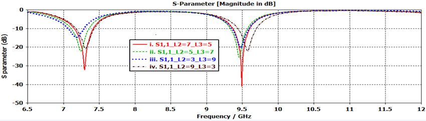
Journal of Communications Vol. 13, No. 6, June 2018

GHz. The bandwidth decreases to 270 MHz (2.85% of                               9.624 GHz.
resonance frequency) at f r 2 ranging from 9.354 GHz to

Fig. 8. Gain vs frequency for dual band reader antenna.

Fig. 9. Radiation efficiency for dual band reader antenna.

B. Parametric Study for the Dual Band Antenna                                   C. Simulation Results of the Optimized Triple Band
   The effects of length variation of Arm2 (denoted as L2 )                            Antenna
and the length of the vertical line (denoted as L3 ) that                           This designed antenna provides resonance at three
                                                                                separate frequency bands. The antenna dimensional
connects horizontal Arm1 and Arm2 on the simulation                             parameters are almost similar to the dual band antenna
result are observed. Due to the variation of lengths of                         discussed in the previous section except that the
 L2 and L3 , both the resonance frequencies of the                              horizontal radiator width that is introduced in Section III-
proposed dual band antenna are changed. The effects of                          B. Various simulation results including return loss ( S11 ),
width variations are shown in Table III. Table III shows                        radiation pattern (both E and H field) and gain versus
the variation of lengths L2 and L3 , and corresponding                          frequency curves are shown in this section.
effects on S-parameter, and resonance frequencies. The                              Fig. 11 shows the reflection co-efficient (S11) of the
overall impact on S-parameter, and radiation effenciency                        triple band reader antenna. Furthermore, Fig. 12, Fig. 13
are shown in Fig. 10 (a), and Fig. 10 (b), respectively.                        and Fig. 14 show the radiation patterns of the antenna at
Table III indicates that when L2 decreases and L3                                f r1 , f r 2 and f r 3 , respectively. The simulated radiation
increases, the S-parameter increases, which means the                           pattern at every resonance frequency band shows the
antenna performance degrades. For all of the cases, the                         main lobe magnitude, 3 dB angular beam width, LSLL,
values of VSWR at both resonance frequencies are less                           and main lobe direction. The lowest side lobe level is -12
than 1.50 which indicates that the antenna impedance is                         dB achieved at f r1 . The gain and directivity at three
resonably matched with the waveguide port impedance.                            resonance frequencies are: 5.79 dB and 6.04 dBi, 6.67 dB
The best result is achieved when L2 =7 mm and L3 =5                             and 7.09 dBi, and 3.88 dB and 4.33dBi at f r1 , f r 2 and
mm,      at    which       S11   =-32.25       and        -41.011   for          f r 3 , respectively. So, the radiation efficiency of this
 f r1 and f r 2 respectively.                                                   triple band proposed antenna are 94.34%, 90.88% and

©2018 Journal of Communications                                           309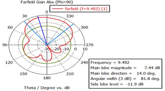
Journal of Communications Vol. 13, No. 6, June 2018
90.09% at f r1 , f r 2 and f r 3 , respectively. The -10 dB resonance frequency) ranging from 9.63 GHz to 9.80
return loss bandwidth at these three resonance GHz, and 587 MHz (4.93% of resonance frequency)
frequencies are 180 MHz (2.33% of resonance frequency) ranging from 11.630 GHz to 12.217 GHz.
ranging from 7.66 GHz to 7.84 GHz, 177 MHz (1.83% of
TABLE III: SPECIFICATIONS OF DUAL BAND ANTENNA WITH VARIATION IN WIDTH.
SL No. Arm2 L3 in mm Resonance frequency S-parameter Radiation Efficiency ( rad )
(L2 in mm) GHz S11 in dB
f r1 fr 2 S11 at f r1 S11 at f r 2 rad (%) at f r1 rad (%) at f r 2
i. 7 5 7.30 9.50 -32.250 -41.011 85.00 87.14
ii. 5 7 7.245 9.46 -22.129 -25.435 84.14 83.17
iii. 3 9 7.185 9.48 -14.770 -20.348 80.16 81.85
iv. 9 3 7.316 9.58 -20.826 -22.055 85.31 86.00
(a)
(b)
Fig. 10. Effects of length variation of L2 and L3 on S-parameter, and Radiation efficiency are shown in (a) and (b) respectively.
Fig. 11. Reflection co-efficient (S11) of the triple band reader antenna.
©2018 Journal of Communications 310
Journal of Communications Vol. 13, No. 6, June 2018

Fig. 12. E and H-plane radiation pattern for triple band reader antenna at   f r1 =7.75 GHz.

Fig. 13. E and H-plane radiation pattern for triple band reader antenna   f r 2 =9.72 GHz.

Fig. 14. E and H-plane radiation pattern for triple band reader antenna at   f r 3 =11.93 GHz.

                                                                                   Rician fading, Doppler spread ( f d ) due to the relative
 V. BER PERFORMANCE OF THE PROPOSED ANTENNAS IN                                    motion of the object with respect to RFID reader along
               THE CENTIMETRE BAND
                                                                                   with path loss. It has been mentioned in the Introduction
   In this section, the BER performance of an RFID                                 Section that OFDM is applied in this research to reduce
system is simulated via MATLAB tool. The detail                                    the effects of multipath fading that exists in outdoor
simulation parameters are shown in Table IV. The                                   scenarios. In order to evaluate the BER performance for
practical RFID system at outdoor may suffer many                                   OFDM based RFID systems, the bandwidths of the
environmental effects such as multipath Rayleigh or                                transmitted signals are considered. It can be noted that the

©2018 Journal of Communications                                              311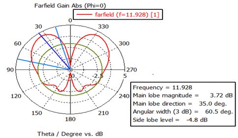
Journal of Communications Vol. 13, No. 6, June 2018
total bandwidth of the signal is divided into the OFDM antenna bandwidth. Due to multipath fading, the power
subcarriers. The OFDM symbol duration which is the received by receiving antennas through line of sight (LOS)
reciprocal of the bandwidth of a subcarrier should be and non-line of sight components (N-LOS) are different
greater than the channel delay spreads ( ). Therefore, and corresponding are also different. We consider
the BER performance is a function of the bandwidth of single tap zero forcing equalizer at the RFID reader
each subcarrier [10]-[13]. An antenna with a large section. In the simulations, an uncoded target BER of 10 -4
bandwidth can effectively receive a signal of the same is considered. This target BER of 10-4 is approximately
bandwidth. In the following, we consider that the equivalent to 10-9 when channel coding is applied.
transmitted signal bandwidth is equal to the reader
TABLE IV: PARAMETERS FOR BER SIMULATIONS
Parameters Quantity/Level
Fading Channel Rayleigh/ Rician
Baseband Modulation QAM
Constellation Points 4, 16
Subcarrier Number 128, 256
Cyclic Prefix (CP) 25%
100 Hz
Doppler Spread ( f d )
Delay Spread (δ) 0.005 ×10⁻¹² Sec
Antenna Bandwidth 180 MHz, 177 MHz, 587 MHz.
(Triple Band)
Antenna Bandwidth (Dual Band) 270 MHz, 300 MHz
Fig. 15. BER performance of different channels at fixed bandwidth 270 MHz.
Fig. 16. BER performance at different resonance frequencies of the proposed antennas.
©2018 Journal of Communications 312Journal of Communications Vol. 13, No. 6, June 2018
Fig. 15 represents the BER as a function of Eb N0 , VI. COMPARATIVE STUDY OF ANTENNAS
the received electrical energy per bit to single sided noise In both of the proposed dual band and triple band
spectral density for the dual band antenna at f r 2 . At f r 2 antennas, the S11 is always less than -10 dB at the
the antenna bandwidth is 270 MHz, so the transmitted resonance frequencies, which indicates that the designed
and the received signal bandwidths are also assumed to antenna impedance is considerably matched with
be 270 MHz. It can be seen that for both Rayleigh and waveguide port impedance. In case of dual band antenna,
Rician fading channels, Eb N0 penalty is occured in the bandwidth at f r1 =7.30 GHz is 300 MHz which is
comparison with AWGN channels. In case of no fading slightly higher than the bandwidth of 270 MHz at
(i.e. AWGN channel), Eb N0 of 8 dB is required to f r 2 =9.50 GHz. At f r1 , the S-parameter is -32.25 dB,
achieve a BER of 10-4. The Eb N0 requirement for whereas at f r 2 , the value of S-parameter is -41.01 dB.
Rician fading channel is 14 dB and for Ralayeigh fading The Lowest Side Lobe Level (LSLL) at H-plane for f r1
channel is 24 dB at a given BER of 10 -4. So, an extra 10 and f r 2 are -16.90 dB and -11.90 dB, respectively. The
dB level of Eb N0 is required for Rayleigh fading than radiation efficiency values for dual band antenna are
Rician fading, since in Rician fading a LOS path exsists 85.00% and 87.14% for f r1 and f r 2 , respectively.
between RFID reader and the tag. In comparison to
Although large bandwidth is more desirable for antennas,
AWGN channels, at a fixed BER of 10-4, aditional 6 dB
a smaller bandwidth means more robustness to multipath
and 16 dB Eb N0 are needed for Rician and Rayleigh fading effects. So, in terms of BER performance,
fading channels, respectively. radiation efficiency and S-parameters, f r 2 is more
Fig. 16 shows the BER as a function of Eb N0 by
preferable than f r1 for RFID communication in outdoor
using the bandwidths (177/270/587 MHz) of the proposed
applications. In case of triple band antenna, the
antennas and the bandwidth (1.28 GHz) of the antenna in
bandwidths at the three resonance frequencies ( f r1 , f r 2
[15]. It is seen that due to the variations of the antenna
bandwidths (also the transmitted/received signal and f r 3 ) are 180 MHz, 177 MHz and 587 MHz,
bandwidths), the Eb N0 requirement is varied for the respectively. The S-parameter and radiation efficiency
same target BER. The graph presents that the Eb N0 levels at f r1 are -25.99 dB, and 94.34%, respectively. On
requirement increases when bandwidth of the the other hand, the S-parameter and radiation efficiency
transmitted/received signal (per subcarrier) increases. For levels at f r 2 are -15.85 dB and 90.88%, respectively.
the same BER (10-4), the Eb N0 requirements for These two parameters have values of -29.34 dB and
bandwidth 177 MHz and 587 MHz are 20.8 dB and 21.5 90.09%, respectively at f r 3 . The LSLL of the proposed
dB, respectively. So, for a bandwidth 587 MHz, triple band antenna at f r1 , f r 2 and f r 3 are -12.1 dB, -2.9
approximately 0.7 dB more Eb N0 is required than a dB and -2.9 dB, respectively. The LSLL for dual band
bandwidth of 177 MHz. This is because as the bandwidth antenna at f r1 is -13.90 dB and -16.90 dB for E and H-
is lower, the symbol period is greater which means that plane, respectively. However, for triple band antenna, the
the delay spread has less influence. Fig. 16 also shows LSLL at f r1 is -12.0 dB and -12.1dB for E and H-plane,
that the BER performance is 1.8 dB better for a signal
bandwidth of 587 MHz (equal to the bandwidth of the respectively. So, the LSLL values are less in dual band
proposed triple band antenna) compared to a signal compared to triple band where the lowest side lobe level
bandwidth of approximately 1.28 GHz which is equal to indicates that maximum power radiates through the main
the bandwidth of the antenna proposed in [15]. lobe.
TABLE V: PERFORMANCE METRICS OF DUAL AND TRIPLE BAND ANTENNAS
Antennas Dual Band Triple Band
Resonant Frequency (GHz) f r1 =7.30 f r 2 =9.50 f r1 =7.75 f r 2 =9.72 f r 3 =11.93
S-parameters (dB) -32.25 -41.01 -25.99 -15.85 -29.34
Bandwidth 300.00 270.25 184.50 177.75 587.00
Rad. Efficiency (%) 85.00 87.14 94.34 90.88 90.09
Gain (dB) 7.628 5.06 5.793 6.674 3.882
Directivity (dBi) 8.339 6.198 6.046 7.089 4.335
Main lobe E-plane 7.51 4.77 5.09 -0.599 3.72
magnitude (dB) H-plane 2.18 7.44 5.79 6.67 -1.62
LSLL (dB) E-plane -13.90 -10.5 -12.0 -4.4 -4.8
H-plane -16.90 -11.9 -12.1 -2.9 -2.9
SNR requirement 21.70 21.0 20.85 20.8 21.5
(dB) to achieve 10-4 BER
©2018 Journal of Communications 313Journal of Communications Vol. 13, No. 6, June 2018
TABLE VI: COMPARISON OF THE PROPOSED ANTENNAS WITH THE LITERATURE.
Antenna Size in mm2 Operating Bands in GHz Bandwidth in GHz Gain (dB)
Ref [5] 100×70 0.915, 2.45 - -
Ref [8] 43×36 10.00 0.29-1.28 13.05, 13.53, 13.64, 13.90
Ref [13] 120×40 2.40, 5.20, 5.80 0.51, 1.01 1.48, 2.30, 3.05
Ref [14] 34.35×29.52 10, 60 0.384 12.84
Ref [15] 52×37 10.5 1.575 3.08
Ref [16] 64×62 2.44 and 5.77 0.014, 0.349 4.96, 7.57
Ref [21] 13×12 2.98, 4.73, 5.70 - 2.59, 3.58, 2.29
Ref [23] 27.5×13 2.40, 3.50, 5.50 - 0.71, .95, 2.36
Ref [25] 100×60 2.4, 5.00 0.12, 2.10 8, 9
Ref [26] 130×130 0.922 0.106 4.9
Proposed Dual 40.30 35.10 7.30, 9.50 0.27, 0.30 5.50, 7.628
Band
Proposed Triple 40.30 35.10 7.75, 9.72, 11.93 0.185, 0.177, 0.587 5.793, 6.674, 3.882
Band
In this section, the proposed dual and triple band 0.8 dB at an uncoded BER of 10-4. Compared with the
antennas are compared with the antennas described in the recent research reported in the literature, the multiband
relevant literature. An important feature of the proposed antennas are shown to have better gain operating at
dual band and triple band antennas is that the sizes of the higher spectrum, without significantly increasing the
designed antennas are smaller than the antennas reported physical dimensions. Experimental measurements of the
in [5], [15]-[18], [34]-[36]. However, the proposed dual proposed antennas are left for future work.
and triple band antenna sizes are larger than the antennas
reported in [37], [38] where the centre frequencies are ACKNOWLEDGMENT
less than those of the proposed antennas. Table VI shows
A portion of this work is a part of M.Sc. thesis of the
that the gain values of the proposed antennas are higher
author Nayan Sarker under the supervision of the author
than those of the reference antennas except the work in
M. Rubaiyat Hossain Mondal to be submitted to the
[15], [17], [18]. Table V also shows that triple band
Institute of Information and Communication Technology
antenna has a resonance frequency at 11.93 GHz which is
(IICT) of Bangladesh University of Engineering and
larger than any frequency described in [15]-[18], [34],
Technology (BUET).
[35], [37]. This makes the proposed triple band antenna
attractive since RFID technology is moving towards
REFERENCES
centimetre and millimetre wave band [39] to solve the
problem of the spectrum crunch. It can also be noted that, [1] K. Finkenzeller, RFID Handbook: Radio-Frequency
both the dual and triple band antennas have bandwidths Identification Fundamentals and Applications, John
lesser than the ones reported in [15], [16]. However, it Wiley& Sons, 2000.
has been shown in Section V that bit error increases when [2] R. Want, “An introduction to RFID technology,” IEEE
the received signal bandwidth increases in a multipath Pervasive Computing, vol. 5, pp. 25-33, 2006.
fading channel. [3] S. B. Miles, S. E. Sharma, and J. R. Williams, RFID
Technology & Applications, New York: Cambridge
VII. CONCLUSION University Press 2011.
[4] C. Varadhan, J. K. Pakkathillam, M. Kanagasabai, R.
Two multiband antennas with centre frequencies in the Sivasamy, R. Natarajan, and S. K. Palaniswamy, “Triband
centimetre band are proposed in this paper. It is observed antenna structures for RFID systems deploying fractal
from simulations that the best values of gain, directivity, geometry,” IEEE Antennas and Wireless Propagation
main lobe magnitude and the lowest side lobe level are Letters, vol. 12, pp. 437-440, 2013.
obtained by the dual band antenna with a centre [5] A. K. Evizal, T. A. Rahman, S. K. B. A. Rahim, and M. F.
frequency of 7.3 GHz. On the other hand, the largest B. Jamlos, “A multi band mini printed omni directional
antenna bandwidth of 587 MHz is obtained by the triple antenna with v-shaped for RFID applications,” Progress
band antenna with a centre frequency of 11.93 GHz. in Electromagnetics Research B, vol. 27, pp. 385-399,
Simulation results also show that when the signal 2011.
bandwidth received by the reader antenna increases from [6] K. Daeyoung, M. A. Ingram, and W. W. Smith,
177 MHz to 587 MHz, the BER performance degrades by “Measurements of small-scale fading and path loss for
©2018 Journal of Communications 314Journal of Communications Vol. 13, No. 6, June 2018
long range RF tags,” IEEE Transactions on Antennas and consequences,” in Proc. International Conference on
Propagation, vol. 51, pp. 1740-1749, 2003. Electrical Engineering and Information Communication
[7] J. D. Griffin and G. D. Durgin, “Complete link budgets Technology, 2015, pp. 1-4.
for backscatter-radio and RFID systems,” IEEE Antennas [22] Y. Yu, J. Ni, and Z. Xu, “Dual-Band dipole antenna for
and Propagation Magazine, vol. 51, pp. 11-25, 2009. 2.45 GHz and 5.8 GHz RFID tag application,”
[8] A. Lazaro, D. Girbau, and D. Salinas, “Radio link budgets International Journal of Wireless Communications and
for UHF RFID on multipath environments,” IEEE Mobile Computing, vol. 3, pp. 1-6, 2015.
Transactions on Antennas and Propagation, vol. 57, pp. [23] S. Genovesi, A. Monorchio, and S. Saponara, “Compact
1241-1251, 2009. triple-frequency antenna for Sub-GHz wireless
[9] G. E. B. a. T. C. P. Dent, Jakes Fading Model Revisited, communications,” IEEE Antennas and Wireless
Vol. 29, pp. 1162-1163, 1993. Propagation Letters, vol. 11, pp. 14-17, 2012.
[10] L. Hanzo, Y. Akhtman, L. Wang, and M. Jiang, MIMO- [24] Y. He, K. Ma, N. Yan, and H. Zhang, “Dual-Band
OFDM for LTE, WiFi and WiMAX: Coherent Versus monopole antenna using substrate-integrated suspended
Non-Coherent and Cooperative Turbo Transceivers, John line technology for WLAN application,” IEEE Antennas
Wiley & Sons Ltd., Oct. 2010. and Wireless Propagation Letters, vol. 16, pp. 2776-2779,
[11] M. R. H. Mondal and S. P. Majumder, “Analytical 2017.
performance evaluation of space time coded MIMO [25] A. K. Gautam, L. Kumar, B. K. Kanaujia, and K.
OFDM systems impaired by fading and timing jitter,” Rambabu, “Design of compact f-shaped slot triple-band
Journal of Communications, vol. 4, pp. 380-387, 2009. antenna for WLAN/WiMAX applications,” IEEE
[12] A. Loulou and M. Renfors, “Enhanced OFDM for Transactions on Antennas and Propagation, vol. 64, pp.
fragmented spectrum use in 5G systems,” Transactions on 1101-1105, 2016.
Emerging Telecommunications Technologies, pp. 31-45, [26] A. K. Sharma, A. Mittal, and B. V. R. Reddy, “Slot
2015. embedded dual-band patch antenna for WLAN and
[13] B. Farhang-Boroujeny, “OFDM versus filter bank WiMAX applications,” Electronics Letters, vol. 51, pp.
multicarrier,” IEEE Signal Processing Magazine, vol. 28, 608-609, 2015.
pp. 92-112, 2011. [27] L. Peng, Y. J. Qiu, L. Y. Luo, and X. Jiang, “Bandwidth
[14] M. M. H. Mishu and M. R. H. Mondal, “Effectiveness of enhanced l-shaped patch antenna with parasitic element
filter bank multicarrier modulation for 5G wireless for 5.8-GHz wireless local area network applications,”
communications,” in Proc. 4th International Conference Wireless Personal Communications, vol. 91, pp. 1163-
on Advances in Electrical Engineering, 2017, pp. 319-324. 1170, December 01 2016.
[15] M. S. Rabbani and H. Ghafouri-Shiraz, “Improvement of [28] S. P. Majumder and K. Mahmud, “Evaluation of detection
microstrip patch antenna gain and bandwidth at 60 GHz range of an active RFID in outdoor environment using
and X bands for wireless applications,” IET Microwaves, receiver diversity with maximal ratio combining,”
Antennas & Propagation, vol. 10, pp. 1167-1173, 2016. International Journal of Information and Electronics
[16] L. Pazin, A. Dyskin, and Y. Leviatan, “Quasi-Isotropic X- Engineering, vol. 5, pp. 322-329, 2015.
band Inverted-F antenna for active RFID tags,” IEEE [29] D. M. Dobkin, The RF in RFID: UHF RFID in Practice,
Antennas and Wireless Propagation Letters, vol. 8, pp. Second Edition ed. vol. 167, 2004.
27-29, 2009. [30] J. S. G. Hong and M. J. Lancaster, Microstrip Filters for
[17] L. Peng, C. L. Ruan, and X. H. Wu, “Design and RF/Microwave Applications, John Wiley & Sons, 2004
operation of dual/triple-band asymmetric m-shaped vol. 167.
microstrip patch antennas,” IEEE Antennas and Wireless [31] S. Szott and M. Natkaniec, “Emerging technologies in
Propagation Letters, vol. 9, pp. 1069-1072, 2010. wireless LANs: Theory, design, and deployment (Bing, B.,
[18] X. Quan, R. Li, Y. Cui, and M. M. Tentzeris, “Analysis Ed.; 2008),” IEEE Communications Magazine, vol. 47, pp.
and design of a compact dual-band directional antenna,” 18-18, 2009.
IEEE Antennas and Wireless Propagation Letters, vol. 11, [32] C. A. Balanis, Antenna Theory: Analysis and Design, 3rd
pp. 547-550, 2012. Edition ed.
[19] X. Liu, Y. Liu, and M. M. Tentzeris, “A novel circularly [33] D. Pozar, M. Microwave Engineering, John Wiley & Sons,
polarized antenna with coin-shaped patches and a ring- 2009.
shaped strip for worldwide UHF RFID applications,” [34] C. M. Wu, C. N. Chiu, and C. K. Hsu, “A new
IEEE Antennas and Wireless Propagation Letters, vol. 14, nonuniform meandered and fork-type grounded antenna
pp. 707-710, 2015. for triple-band WLAN applications,” IEEE Antennas and
[20] D. Najeeb, D. Hassan, R. Najeeb, and H. Ademgil, Wireless Propagation Letters, vol. 5, pp. 346-348, 2006.
“Design and simulation of wideband Microstrip patch [35] C. K. Hsu and S. J. Chung, “Compact multiband antenna
antenna for RFID applications,” in Proc. HONET-ICT, for handsets with a conducting edge,” IEEE Transactions
2016, pp. 84-87. on Antennas and Propagation, vol. 63, pp. 5102-5107,
[21] S. H. Shehab, S. Hassan, M. A. I. Oni, S. Dey, and M. M. 2015.
Hassan, “Design and evaluation of an elliptical patch [36] X. Z. Lai, Z. M. Xie, and X. L. Cen, “Design of dual
textile antenna for RFID application and bending circularly polarized antenna with high isolation for RFID
©2018 Journal of Communications 315Journal of Communications Vol. 13, No. 6, June 2018
application,” Progress In Electromagnetics Research B, Md. Aminul Islam (S'11, M'15)
vol. 139, pp. 25-39, 2013. received the B.Sc. degree in electrical
[37] X. Li, X. W. Shi, W. Hu, P. Fei, and J. F. Yu, “Compact and electronic engineering from
triband ACS-Fed monopole antenna employing open- Bangladesh University of Engineering
ended slots for wireless communication,” IEEE Antennas and Technology (BUET), Dhaka,
and Wireless Propagation Letters, vol. 12, pp. 388-391, Bangladesh, in October 2009, and the
2013. Ph.D. degree from Monash University,
[38] A. Boukarkar, X. Q. Lin, Y. Jiang, and Y. Q. Yu, Clayton, Victoria, Australia, in October
“Miniaturized single-feed multiband patch antennas,” 2014. He worked as a Research Support
Officer at Monash Microwave, Antennas, RFID, and Sensor
IEEE Transactions on Antennas and Propagation, vol. 65,
(MMARS) laboratory in 2014–2015. Currently, he is working
pp. 850-854, 2017.
as an Assistant Professor at the Military Institute of Science and
[39] K. Wu, P. Burasa, T. Djerafi, and N. Constantin,
Technology (MIST), Bangladesh. His research interest is in
“Millimeter-wave identification for future sensing,
chipless RFID tag, reader, and antenna designing.
tracking, positioning and communicating systems,” in
Proc. Global Symposium on Millimeter Waves (GSMM) & M. Rubaiyat Hossain Mondal received
ESA Workshop on Millimeter-Wave Technology and the B.Sc. and M.Sc. degrees in electrical
Applications, Espoo, 2016, pp. 1-4. and electronic engineering from
Bangladesh University of Engineering
Nayan Sarker received the B.Sc. in and Technology (BUET), Dhaka,
electronics and communication Bangladesh in 2004 and 2007,
engineering (ECE) degree from Khulna respectively. He obtained the Ph.D.
University of Engineering and degree in 2014 from the Department of
Technology (KUET), Khulna, Electrical and Computer Systems Engineering, Monash
Bangladesh in October, 2014. University, Melbourne, Australia. From 2005 to 2010, and from
Currently, he is pursuing M.Sc. 2014 to date he has been working as a Faculty Member at the
engineering degree at the Institute of Institute of Information and Communication Technology (IICT)
Information and Communication in BUET. His research interests include wireless
Technology (IICT) in Bangladesh communications, optical wireless communications, OFDM,
University of Engineering and Technology (BUET), Dhaka, image processing and machine learning.
Bangladesh. He is also working as a lecturer at Bangladesh
University of Business and Technology (BUBT), Dhaka,
Bangladesh. His research interest is antenna design for active
and passive RFID systems, IOT, OFDM and signal security.
©2018 Journal of Communications 316You can also read