Crack propagation modeling of strengthening of RC deep beams with CFRP plates
←
→
Page content transcription
If your browser does not render page correctly, please read the page content below
Preprints (www.preprints.org) | NOT PEER-REVIEWED | Posted: 22 February 2021 doi:10.20944/preprints202102.0471.v1

 Article

 Crack propagation modeling of strengthening of RC deep
 beams with CFRP plates
 Shahriar Shahbazpanahi1, Hogr Karim2, and Wrya Abdullah3, Amir Mosavi 4*

 1 Department of Civil Engineering, Sanandaj Branch, Islamic Azad University, Kurdistan, Iran;
 sh.shahbazpanahi@iausdj.ac.ir (S.S.)
 2 Civil Engineering Department, University of Halabja, Halabja, Kurdistan Region, Iraq; hogrka-
 rim@uoh.edu.iq (H. K.)
 3 Civil Engineering Department, College of Engineering, University of Sulaimani, Kurdistan Region, Iraq
 wrya.faraj@univsul.edu.iq (W. A.)
 4 Thuringian Institute of Sustainability and Climate Protection, 07743 Jena, Germany
 a.mosavi@ieee.org (A. M.)

 * Correspondence: a.mosavi@ieee.org

 Abstract: Fracture analysis of reinforced concrete deep beam strengthened with carbon fi-
 ber-reinforced polymer (CFRP) plates was carried out. The present research aims to find out
 whether the crack propagation in a strengthened deep beam follows linear elastic fracture me-
 chanics (LEFM) theory or nonlinear fracture mechanics theory. To do so, a new energy release rate
 based on nonlinear fracture mechanics theory was formulated on the finite element method and the
 discrete cohesive zone model (DCZM) was developed in deep beams. To validate and compare
 with numerical models, three deep beams with rectangular cross-sections were tested. The code
 results based on nonlinear fracture mechanics models were compared with experimental results
 and ABAQUS results carried out based on LEFM. The predicted values of initial stiffness, yielding
 point and failure load, energy absorption, and compressive strain in the concrete obtained by the
 proposed model were very close to the experimental results. However, the ABAQUS software re-
 sults have greater differences with the experimental results. For example, the predicted failure load
 for the shear-strengthened deep beam using the proposed model has only 6.3% differences com-
 pared to the experimental result. However, the predicted failure load using ABAQUS software
 based on LEFM has greater differences (25.1%) compared to the experimental result.

 Keywords: CFRP; concrete; deep beam; propagation

 1. Introduction
 Reinforced concrete deep beams play an essential role in bridges, buildings, offshore
 structures, foundations, and military structures [1,2,3]. Pile caps in Foundations, coupling
 beams in buildings, transfer beams, load-bearing walls, and bunker walls behave as deep
 beams [4]. In the deep beam, the span to effective depth ratio is less than or equals to 2.0
 [5] and the transverse plane sections before bending do not remain plane after bending
 [6].
 In general, cracks in a concrete structure, such as deep beams, start in the tension
 zone due to increasing stresses or the presence of initial cracks [7]. Therefore, these cracks
 must be studied properly. Two approaches are existing to study crack propagation in
 concrete structures [8]. They can be divided into two general categories such as Linear
 Elastic Fracture Mechanics (LEFM) and nonlinear fracture mechanics theories. LEFM
 theory, for the first time, was applied to analyze fracture mechanics on ships used in
 World War II [9]. In the LEFM theory, to calculate the real stress, a factor is multiplied on
 the stress near ahead of crack which the researchers called it stress intensity factor (SIF). If
 the principal stress in crack-tip reaches the fracture toughness, the crack propagates. The

 © 2021 by the author(s). Distributed under a Creative Commons CC BY license.
Preprints (www.preprints.org) | NOT PEER-REVIEWED | Posted: 22 February 2021 doi:10.20944/preprints202102.0471.v1

 SIF changes with the size of the crack, load, geometry of the structure, and the material
 properties. One of the most characteristics of LEFM theory is stress singularity at the
 crack tip. Kaplan's [10]research showed that LEFM theory is not acceptable for nor-
 mal-sized concrete structures and can be used to investigate the propagation of cracks in
 mass structures such as concrete dams. Later, researchers found a zone in front of cracks
 in a normal-sized concrete structure and called it the fracture process zone (FPZ). The
 behavior of this zone is non-linear and a lot of energy is accumulated in this area that if it
 exceeds a certain level (fracture energy) the behavior will cause softening [11] [12,13,14].
 Modeling of this area is important for concrete structural members, such as beams, joints,
 and deep beams, and it has been studied in recent years. The FPZ is not used in the LEFM
 theory [15,16]. One of the most successful and accurate methods in modeling this area is
 the discrete cohesive zone model (DCZM) that was developed in the present study
 [17,18,19].
 On the other hand, by using different kinds of strengthening, the crack propagation
 of concrete changes. In recent years, Carbon Fiber Reinforced Polymer (CFRP) plates
 have been applied in concrete structures. Advantages of this type of retrofitting are low
 weight, corrosion resistant, easy installation, and high tensile strength [20,21,22]. Now-
 adays, strengthening using CFRP is of interest from an economic point of view [23]. The
 use of CFRP composites is now identified as a successful, suitable, and efficient technique
 to strengthen structures [24].
 Because CFRP plates affect the initiation and propagation of cracks in concrete
 members, including deep beams, it is necessary to model, test, and study these members.
 Due to shear crack, the strengthening of deep beams in the shear region is significant.
 shear cracks propagate more in deep beams compare with flexural cracks.
 Although, it was expected in advance that flexural strengthening of a deep beam in
 the flexural-zone (soffit strengthen of the deep beam) could not enhance their
 load-displacement behavior. To verify this issue, however, such strengthening was per-
 formed in this study. Indeed, capacity of deep beams is rather affected by
 shear-strengthening (side face of the deep beam) than flexural-strengthening.
 There are many experimental works on deep beams and CFRP shear–strengthened
 deep beams [25,26]. However, there is limited knowledge about crack propagation in a
 concrete deep beam strengthened with CFRP plates in flexural and shear regions can be
 found in the literature. It is vital to carry out experimental tests to better understand the
 crack propagation pattern of concrete deep beams strengthened with CFRP plates.
 The present research aims to find out whether the crack propagation in a strength-
 ened deep beam follows LEFM theory or nonlinear fracture mechanics theory. Therefore,
 a new energy release rate based on nonlinear fracture mechanics theory was formulated
 using finite element method. In this study, a numerical model was proposed to simulate
 the FPZ. To validate and compare with the numerical models, three deep beam speci-
 mens with rectangular cross-sections were tested. One of the deep beams was considered
 as a control specimen. Another deep beam was strengthened in flexural with CFRP plats
 at the bottom and the last one was strengthened in shear with CFRP plates in both sides
 of the shear span of the beam. The three beams were loaded with two-point monotonic
 loads until failure. The results of the FEAPpv® program code based on the nonlinear
 fracture mechanics were compared with experimental results with the results of the
 FEAPpv® program code based on the nonlinear fracture mechanics model and ABAQUS
 software based on LEFM..

 2. Materials and Methods
 2.1 Numerical model
 2.1.1. Proposed numerical model based on nonlinear fracture mechanic
 The Finite Element Analysis Programs personal version (FEAPpv) are processor
 evaluation methods considered for utilizing in an instructional package to show the
 presence of the platform of elements and simulation. FEAPpv has only command lan-
 guage and designed for research by Taylor [27]. In this program, the solution algorithm is
Preprints (www.preprints.org) | NOT PEER-REVIEWED | Posted: 22 February 2021 doi:10.20944/preprints202102.0471.v1

 written by the operator. Therefore, each operator can describe a solution plan that meets
 specific needs. The system includes enough commands that can be applied for use in
 mechanics, structural, heat transfer, fluid, and other areas by differential equations. Sev-
 eral numerical models have been accomplished by FEAPpv [28,29,30,31,32,33].
 To estimate shear crack propagation for concrete deep beam, a new formulation of
 energy release rate based on the finite element method is introduced. To compute the
 strain energy release, the virtual crack closure technique (VCCT), which is the most
 popular and powerful tool on DCZM, is used [17]. A small concrete deep beam element
 in the shear span is shown in Figure 1. A truss element as the interface is set between in-
 terfacial node pairs, nodes 1 and 2. Initially, nodes ‘1’ and ‘2’ have the same coordinates.

 y

 x 1 2

 ∆ Truss

 Figure 1. A part of a concrete deep beam

 The stiffness of the interface element that selected as truss element, in the elastic
 zone (no crack propagates) based on VCCT is given by [18]:

 EB∆
 kx = , (1)
 h
 GB∆
 ky = , (2)
 h

 where , , , ∆ and ℎ are Young’s modulus of concrete, shear modulus, the
 width of the deep beam, mesh size, and height of the deep beam, respectively. , and
 are the stiffness of the interface element in x and y directions, respectively. The
 cracking stress proposed by Thomasa et al. [34] is adopted to model the initial shear
 crack as:
 '
 σstart =0.24 1.25fc , (3)

 '
 where σstart and fc are cracking stress and concrete compressive strength, MPa, re-
 spectively. If the principal stress in Node ‘1’ or ‘2’ was equal to Eq. (3), the stiffness’s in
 Eqs. (1) and (2) were zero and cracks were created. The normal stress of crack propaga-
 tion by Walraven [35] is adopted to find strain energy release rates in the deep beam.

 1
 ' 3
 σN =C.K.(100ρfc ) , (4)
 where σN , ρ, K, and C are normal stress, longitudinal reinforcement ratio, size
 factor, and a coefficient (about 0.12), respectively. The K is given by:

 K=1+ 200⁄d , (5)
 where d is the effective depth in mm. It was assumed that cross section of the truss
 element is equal to A=B×∆. The strain energy release rates of Mode I, GI is expressed as
 follows [36]:
Preprints (www.preprints.org) | NOT PEER-REVIEWED | Posted: 22 February 2021 doi:10.20944/preprints202102.0471.v1

 FN (x1 -x2 ) σN (x1 -x2 )
 GI = = , (6)
 2B∆ 2

 where FN , x1 and x2 are nodal force, displacement of node ‘1’and ‘2’ in x direction,
 respectively. The shear stress of crack in the deep bem is adopted by zhang et al. [37] as:
 τN =A+B σN , (7)
 where A and B are the shear cohesive and frictional that are:
 ' 0.665
 A=0.347 fc , (8)
 ' ' 0.665
 0.4fc -0.37-0.347 fc
 B= '
 , (9)
 0.25fc
 Therefore, the strain energy release rates for shear, GII , is based on work by Xie et
 al [18] as follows:
 τN (y1 -y2 )
 GII = , (10)
 2
 On the other hand, the GF is the critical fracture energy of concrete deep beam
 which is equal to [38]:
 0.18
 GF =0.073(ft ) , (11)
 where ft is the tensile strength of concrete. Therefore, when GI + GII < GF , the
 stiffnesses are equal to Eqs. (1) and (2). When GI + GII > GF , the crack is propagated, the
 interface element is removed and Eqs. (1) and (2) becomes zero. In addition, to find fail-
 ure stress, ultimate shear stress by Thomas et al. [39] is used.
 Furthermore, a numerical method is developed to model crack propagation
 based on the mentioned new strain energy release rates in the reinforced concrete deep
 beam which is flexural-strengthened with CFRP [40,41]. Also, in this study, a computer
 code was developed specifically to model shear-strengthening of the reinforced concrete
 deep beam by modifying the crack propagation criteria [42].

 2.1.2 Numerical model based on LEFM
 To compare with the experimental results and FEAPpv based on nonlinear fracture
 mechanics, the ABAQUS software is used to model crack propagation by conventional
 cohesive elements. ABAQUS software can only model the crack propagation based on
 linear fracture mechanics and it cannot capable of simulating nonlinear fracture me-
 chanics. Concrete parameters used for deep beam based on LEFM in ABAQUS are given
 in Table 1.

 Table 1. ABAQUS Parameters of concrete deep beam based LEFM.

 Parameter Description Value
 ∈ Eccentricity 0.1
 Dilation angle 56
 Viscosity
 0.0001
 Parameter
 The second
 Κ stress invariant/ 0.66
 tensile meridian

 2.2. Experimental test of control and CFRP deep beams

Preprints (www.preprints.org) | NOT PEER-REVIEWED | Posted: 22 February 2021 doi:10.20944/preprints202102.0471.v1

 Experimental tests were conducted under static monotonic load to validate the
 simulation results. Results from both models were compared with the experimental re-
 sults of three deep beams.

 2.2.1 Specimens
 Figure 2 illustrates the deep beam dimensions which are 500 mm in depth, 150
 mm in width, and 900 mm in length. The geometry, supports, and details of the deep
 beams are also shown in Figure 2. The deep beams were reinforced longitudinally with
 two 16 mm diameter steel rebars at bottom and two 12 mm diameter steel rebars at top
 with 30 mm clear concrete cover. The deep beams were not reinforced transversally in
 order to guarantee the shear failures. Only two stirrups were used out of the shear zone
 to hold the longitudinal reinforcement in place as shown in Figure 2. The yield strength
 of the bars was 400 MPa based on the manufacturer report. Average concrete compres-
 sive strength was 28 MPa (at 28 days) based on testing three cylinders with diameter of
 150 mm and height of 300 mm. Table 2 shows mix design for the concrete used to cast the
 deep beams. The mechanical properties of the CFRP plates were found according to
 ASTM D7565 [43]. The properties of the CFRP plates and steel reinforcement are given in
 Table 3. B-0, B-1 and B-2 are used to designate the control deep beam, the flexural
 strengthened and the shear strengthened deep beams, respectively. All the deep beams
 have the same steel reinforcement as shown in Figure 2.

 2 Stirrups D8

 D12
 St. D8

 D16
 500

 150
 900

 (a)

 300 300 300
 CFRP
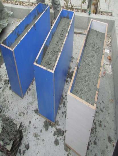
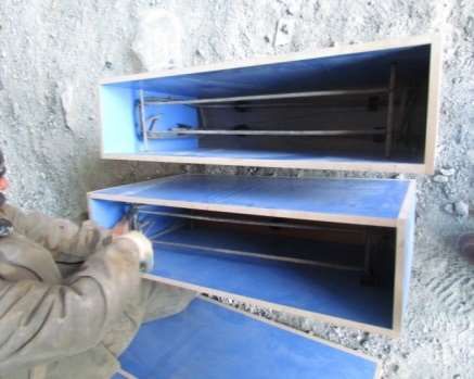
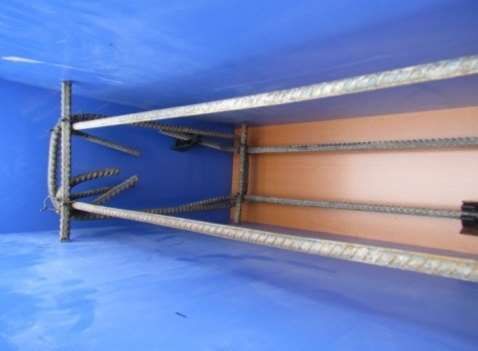
Preprints (www.preprints.org) | NOT PEER-REVIEWED | Posted: 22 February 2021 doi:10.20944/preprints202102.0471.v1

 (b)

 CFRP

 400
 300 300 300

 (c)

 Figure 2. The detail and boundary condition of deep beams(a) Control deep beam, (b) Flexural–
 strengthened and (c) Shear–strengthened by CFRP plates (Unit: mm).

 Table 2. Mix proportions for the concrete mix.

 Coarse Fine aggre-
 Mix Cement Water
 W/C aggregate gate
 design kg/m3 kg/m3
 kg/m3 kg/m3

 Concrete 0.41 445.00 270 1000 746

 Table 3. Properties of the CFRP plates and steel reinforcement.

 Item Value
 Type of CFRP bidirectional
 Elastic modulus (GPa) 250
 Strain (%) 1.09
 Tensile strength (MPa) 210
 Thickness (mm) 0.8
 Epoxy resin Density (kg /l) 1.7
 Epoxy resin tensile strength (MPa) 14
 Modulus of Elasticity of epoxy resin (GPa) 4
 Yield strength (MPa) of steel 400
 Ultimate strength (MPa) of steel 580
 Modulus of elasticity(GPa) of steel 200

 Three plywood formwork (Figure 3(a)) are built to cast the deep beams. Figure 3(b)
 shows the reinforcement cage layout inside the formwork. After casting (Figure 4), the
 beams were tested after 28 days in the. The deep beams were simply supported and
Preprints (www.preprints.org) | NOT PEER-REVIEWED | Posted: 22 February 2021 doi:10.20944/preprints202102.0471.v1

 tested under two equal concentrated loads.. For the B-1 deep beam, the CFRP plate was
 externally bonded at the bottom of the beam. For the B-2 deep beam, the CFRP plate was
 bonded into the both sides of the deep beam in the shear span. Whereas, the CFRP
 shear-strengthened plates are not fully wrapped, they are interrupted at a 100 mm from
 the top of the beam.

 (a) (b)
 Figure 3. Detail of bars and three deep beams (a) Frameworks and (b) Bars inside the frame-
 work.

 Figure 4. Casting by concrete of three deep beam.

 2.2.2 Instrumentation

 A hydraulic jack with 800 kN capacity was used to the deep beam. The mid-span
 displacements (Figure 5) were recorded by Linear Variable Displacement Transformers
 (LVDTs). Two strain gauges were attached directly under the CFRP plates and concrete
 below the load to observe strain. The supports were placed at the bottom of the concrete
 beams. The applied loads were measured by a load cell. All the measurements were au-
 tomatically recorded using a data logger.

 Hydraulic jack
 Load distribution frame
 Load cell
 Strain gage
 CFRP plate

 LVDT
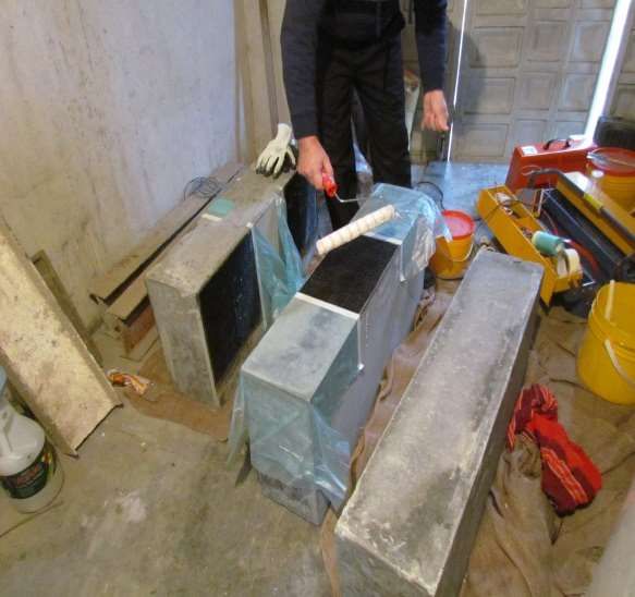
Preprints (www.preprints.org) | NOT PEER-REVIEWED | Posted: 22 February 2021 doi:10.20944/preprints202102.0471.v1

 Figure 5. Details of the loading system and measurement schemes.

 Before strengthening the specimens with CFRP plates, the concrete surface was
 cleaned to remove any surface grease. The surfaces of the specimens were further cleaned
 by grinding and brushing. An epoxy adhesive was uniformly applied in a thin layer on
 the bonding surfaces as shown in Figure 6. The CFRP was placed over it and pressed
 firmly by plastic rollers. External strengthening with single-layer CFRP plates has a
 thickness of 0.8 mm and an elastic modulus of 250 GPa. The ultimate tensile stress of the
 CFRP plates was 210 GMPa.

 Figure 6. Apply of the CFRP plates on B-1 and B-2 deep beam.

 2.2.3 Test set-up and technique
 Figure 7 illustrates the test setup details for the control beam (B-0), the beam
 with flexure strengthened by CFRP (B-1), and the beam with shear strengthened by CFRP
 plates (B-2). A strain gauge was mounted on the surface of concrete to record strain in the
 concrete. A four-point bending test setup was used to test the beams. One LVDT was set
 to monitor the displacements under deep beam. A load cell was utilized to measure the
 applied load. The test was conducted under a gradually increasing monotonic load (at a
 loading rate of 0.4 mm/min) until beam failure was reached.

 (a)
Preprints (www.preprints.org) | NOT PEER-REVIEWED | Posted: 22 February 2021 doi:10.20944/preprints202102.0471.v1

 (b)

 (c)

 Figure 7. Deep beams set up before test (a) control, (b) flexural and(c) shear–
 strengthened.

 3. Results
 This section presents the validation and comparison of crack propagation obtained
 by the proposed model based on the nonlinear fracture mechanics theory, the experi-
 mental results, and ABAQUS software results based on LEFM.

 3.1. Crack propagation in the control beam (B-0)

 The control beam was studed first to compare the proposed model with experimental
 results. A comparison of the proposed model based on nonlinear fracture mechanics
 theory with the experimental results is shown in Figure 8. A good agreement between the
 experimental results and proposed model results based on nonlinear fracture mechanics
 theory was found out for the load-deflection curves in the mid-span, as shown in Figure
 8. The load-deflection curves showed nonlinear behavior. The initial stiffness obtained by
 the nonlinear fracture mechanics model coincides with the stiffness of the beam at the
 elastic zone, as predicted by the experimental results. The initial stiffness obtained by the
 linear elastic fracture mechanics model by ABAQUS was over- estimated and had
 significantly higher stiffness in the mid-span. For the deep beams simulated based on
 LEFM by ABAQUS, at the same load level, displacements were lower compared to the
 experimental results. The results of the proposed model based on nonlinear fracture
 mechanics theory provided an accurate steel yield load point, compared with the
 experimental results. Thus, the nonlinear fracture mechanics model can detect yield
 stress in the steel with reasonable accuracy. The most obvious effect of the nonlinear
 fracture mechanics model on deep beam response can be seen in the plastic zone. The
 proposed model in the plastic zone corresponds close to the experimental results. Based
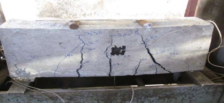
Preprints (www.preprints.org) | NOT PEER-REVIEWED | Posted: 22 February 2021 doi:10.20944/preprints202102.0471.v1

 on the nonlinear fracture mechanics model, the failure load is 350.7 kN, whereas the
 experimental result is 331.2 kN. Failure load based on the LEFM model by ABAQUS was
 401.3. Thus, the nonlinear fracture mechanics model can accurately predict the failure
 load.

 400

 300

 Load (kN)
 200 Proposed model by FEAP

 Experimental results
 100
 LEFM model by ABAQUS

 0
 0 1 2 3 4 5

 Deflection at midspan (mm)

 Figure 8. Load-deflection curves of control deep beam (B-0).

 Figure 9 shows the crack paths of the control beam, which were modeled using the
 nonlinear fracture mechanics model. Only half of the beam was modeled by considering
 symmetry. Figure 10 illustrates the crack path through the experimental test. This crack
 pattern may be compared with the predicted result shown in Figure 9. The nonlinear
 fracture mechanics model predicted three cracks within the shear span compared with
 the three cracks observed in the experimental test. Shear span is the distance between a
 support and the nearest load point. The nonlinear fracture mechanics model observed
 one big and one small flexural crack within the flexural zone whereasonly one crack
 was observed in the experimental result. Flexural span is the distance between the point
 loads. The agreement between the crack paths obtained in the nonlinear fracture
 mechanics model and the experimental test is sufficient to justify the validity of the
 nonlinear fracture mechanics model. The crack patterns obtained by the nonlinear
 fracture mechanics model and experimental results, were propagated to the last quarter
 of the section height. Figure 11 shows the crack paths of the control beam simulated using
 the ABAQUS software based on LEFM. The shear crack near the support cannot be
 modeled by conventional ABAQUS software. Therefore, the nonlinear fracture
 mechanics model more objectively predicts crack propagation compared with the
 ABAQUS software. As shown in figures 9, 10, and 11 the model of control deep beam
 works better with FEAPpv based on nonlinear fracture P mechanics than ABAQUS based
 on LEFM. P

 Figure 9. Crack path obtained by nonlinear fracture mechanics model (B-0).
Preprints (www.preprints.org) | NOT PEER-REVIEWED | Posted: 22 February 2021 doi:10.20944/preprints202102.0471.v1

 Figure 10. Crack path observed by experimental test (B-0).

 Figure 11. Crack Path by ABAQUS FEA Software(B-0).

 Figure 12 compares the load versus the mid-span deflection of the deep beam
 obtained by the proposed model based on nonlinear fracture mechanics theory, the
 results of the experimental test, and the ABAQUS software. The results of the proposed
 model are consistent with the results of the nonlinear fracture michanics. Stiffness of the
 deep beam predicted based on the LEFM had smaller differences compared with the
 experimental results. However, the stiffness of the deep beam predicted based on
 ABAQUS is more than the experimental results stiffness. The steel yield load predicted
 by LEFM has about 4% difference compared to the experimental result. However, the
 steel yield load by ABAQUS software has greater error (31%) compared to the
 experimental result, which indicates that it is less capable of estimating the steel yield
 load. Compared with that in the experimental results, load failure in the poroposed
 model was predicted within a difference range of 5.6% to 8%. The load-deflection curve
 of the nonlinear fracture mechanics model was similar to the experimental results.
 However, the load-deflection curve by ABAQUS software was higher than the
 experimental curve. The ABAQUS software results have a greater amount of difference
 (29.9-39.4%) compared with the experimental results. Remarkably, the proposed model
 based on the nonlinear fracture mechanics model could be used to perform analysis of
 reinforced deep beam flexural–strengthened by CFRP plates.
Preprints (www.preprints.org) | NOT PEER-REVIEWED | Posted: 22 February 2021 doi:10.20944/preprints202102.0471.v1

 500
 Failure load
 400 Steel yielding

 Load (kN)
 300

 200

 Proposed model by FEAPV
 100
 Experimental results
 LEFM model by ABAQUS
 0
 0 2 4 6
 Deflection at midspan (mm)

 Figure 12. Load-deflection of the flexural- strengthened deep beam (B-1)

 Figure 13 shows the comparison of crack patterns between the proposed model, the
 experiment, and the ABAQUS software in the deep beam with flexure strengthened by
 CFRP plates. The predicted cracking pattern of the proposed model is generally
 consistent with the experimental observations. In both cases, the flexural cracks were
 closely spaced near the beam mid-span, as shown in Figures 13(a) and 13(b). Within the
 shear span, the model predicted two shear–flexural cracks, whereas only one crack was
 observed in the experiment (left shear span) in half of the beam. The model predicted one
 shear crack near the support, whereas no crack was observed in the test. The shear cracks
 may be too small to be noticed in the experimental test. As shown in Figure 13(c), the
 ABAQUS software cannot simulate this crack pattern because neither the accurate
 stiffness of the FPZ nor the crack propagation criterion is considered in the software.
 Flexural crack was observed by the nonlinear fracture mechanics model in the control
 beam near the mid-span at a load level of 280 kN. Whereas, crack of the beam with
 strengthened in flexure occurred at a relatively higher load level (300 kN) than that for
 the control beam. Observed flexural crack load for the flexural strengthened deep beam
 was about 300 kN based on the nonlinear fracture mechanics and the experimental
 results. The deep beam that strengthened in flexure showed approximately 2% shorter
 flexural crack length compared to the control beam. As expected, the behavior of the
 flexural strengthened deep beam with CFRP plates was slightly changed compared to the
 control deep beam. Finally, the beam failed because of shear failure with a large shear
 crack.

 P

 (a)
Preprints (www.preprints.org) | NOT PEER-REVIEWED | Posted: 22 February 2021 doi:10.20944/preprints202102.0471.v1

 (b)

 (c)

 Figure 13. Crack pattern of the flexural-strengthened deep beam (a) proposed model, (b)
 experimental, and(c) ABAQUS.

 3.3 Crack propagation in the shear–strengthened deep beam (B-2)

 The load-deflection curves obtained from the experimental test, the nonlinear
 fracture mechanics model, and the ABAQUS software for the deep beam with shear
 strengthened by CFRP plates are shown in Figure 14. The results of the proposed model
 are close to that of the experimental one. This finding indicates that the nonlinear fracture
 mechanics model is validated by the test results. The yield point of the load-deflection
 curve in the nonlinear fracture mechanics model is similar to that in the experimental test
 result (about 3% difference). However, this point obtained in the LEFM simulations by
 ABAQUS was higher than that in the experimental test result (about 21% difference). The
 accuracy of the proposed model is also confirmed by the close value of the failure load
 obtained from the proposed model and the test (about 2% difference at 4 mm deflection).
 Also, the stiffness of the beam with shear strengthened by CFRP as analyzed by the
 ABAQUS software is over- estinated.
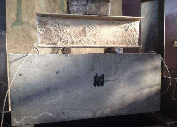
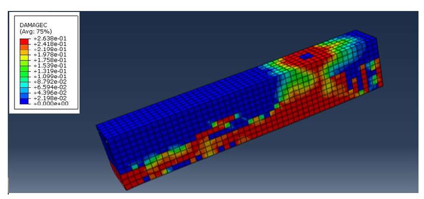
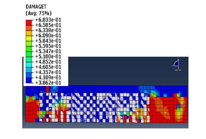
Preprints (www.preprints.org) | NOT PEER-REVIEWED | Posted: 22 February 2021 doi:10.20944/preprints202102.0471.v1

 500

 400

 300

 Load (kN)
 Proposed model by FEAPV
 200 Experimental results
 LEFM by ABAQUS
 100

 0
 0 1 2 3 4 5
 Deflection at midspan (mm)

 Figure 14. Load-deflection of the shear–strengthened deep beam (B-2).

 Figure 15 shows the crack paths obtained by the proposed model, the experimental
 results, and the cracks predicted in the FEA by ABAQUS. A good agreement is observed
 for the crack paths predicted by the proposed model compared with the experimental
 result, as shown in Figures 15(a) and 15(b). Figures 15(a) and 15(b) show that only one
 flexural crack initiated and propagated towards the loading point. Only one shear–
 flexural crack is observed near the CFRP plate. The shear cracks stopped initation and
 propagation in the shear span because of the shear strengthened with CFRP plates. The
 flexural crack began to appear at a load of approximately 240 kN. The flexural–shear
 cracks propagated from the mid-depth of the beam toward the point of the applied load.
 As the load increased, the flexural–shear crack propagated to the final failure. A
 comparison of the shear cracks in the beam with strengthened in shear [see Figure 15(a)]
 and the control beam [see Figure 10] shows that there are more shear cracks in the
 control beam. The use of CFRP plates affected on and delayed the propagation of the
 shear crack.

 Figure 15(c) shows the crack paths obtained by ABAQUS based on the LEFM. By
 comparing Figures 15 (a), (b), and (c), the nonlinear fractures mechanics model for the
 shear–strengthened deep beam with CFRP are comparatively better than the LEFM by
 ABAQUS.

 Figure 16 shows the effect of shear strengthened by CFRP on the crack propagation. Only
 one small crack formed under the CFRP plate, as shown in Figure 16. CFRP plates delay
 and control cracking in the beam and confine the crack propagation of concrete. Shear
 strengthened by CFRP plate reduces the width of cracks in concrete. Figure 16 shows that
 crack was not observed in the shear span because of the presence of CFRP plates. The
 crack length was restrained as well.

 P
Preprints (www.preprints.org) | NOT PEER-REVIEWED | Posted: 22 February 2021 doi:10.20944/preprints202102.0471.v1

 (a)

 (b)

 (c)

 Figure 15. The crack pattern of the shear-strengthened deep beam (a) proposed model, (b)
 experimental, and (c) ABAQUS.

 In Table 4, some factors such as accuracy of predicted initial stiffness, yielding point
 (based on the same load), plastic zone, and failure point for each model were compared
 with the experimental results. The predicted values of initial stiffness, yielding point,
 and failure point obtained by non-linear fracture mechanics were very close to the
 experimental results. However, the ABAQUS software results based on LEFM have a
 greater discrepancy. For example, the steel yielding point in the control deep beam was
 predicted by non-linear fracture mechanics within a difference of 1.2%. However, the
 steel yield load by ABAQUS software based on LEFM has a higher difference (13%)
 compared to the control beam, which indicates that it is less capable of estimating the
 steel yield load. The failure loads based on the non-linear fracture mechanics and the
 experimental results for the shear strengthened deep beam, were about 485 and 498 kN
 corresponding to mid-span displacements of 4.1 and 4.5 mm, respectively. However,
 these values for the model based on LEFM were equal to 510 kN with mid-span
 deflections of 3.7 mm. For the shear strengthened deep beam (B-2), delamination of
 the CFRP plates was evident based on the non-linear fracture mechanics model and the
 experimental results. However, the model based on LEFM showed that failure occurs
 because of the rupture of the CFRP plates on the shear span.
 Table 4: Comparison both model with results of experimental (at the same load)
Preprints (www.preprints.org) | NOT PEER-REVIEWED | Posted: 22 February 2021 doi:10.20944/preprints202102.0471.v1

 Deep beam
 stiffness Yielding Plastic Failure load Failure mode Failure mode by
 Model
 (%) (%) zone (%) (%) by models experimental

 Proposed model
 2-6 1.2 9-11 6.3 Shear
 Shear

 Control (B-0) LEFM 12-19 40 16-24 23.6 Shear
 Flexural Strength- Proposed model 1-4 4 5-7 5.6-8.0 Shear
 Shear
 ening (B-1) LEFM 10-16 31.1 14-20 29.9-39.4 Shear
 Shear Strengthening Proposed model 6-10 3 1-3 2.6 Delamination CFRP Delami-
 (B-2) LEFM 22-35 21 34-53 25.1 CFRP rupture nation

 In Table 5, the energy absorption (the area under the load-deflection curve) is listed for
 each deep beam at failure load. The calculated energy absorptions for the control deep
 beam were 987, 1029, and 1154 kN.mm based on the experimental, the proposed model,
 and the LEFM results, respectively. The energy absorption for the control deep beam
 obtained from the experimental results is slightly lower than that found by the proposed
 model. Also, for the strengthened deep beams in shear, the energy absorption obtained
 by LEFM is much higher than that of the experimental results and the proposed model.
 The shear strengthened deep beam showed an increase in the energy absorption up to
 67.1% compared to the control deep beam. The experimental compressive strain for the
 shear-strengthened deep beam was greater than the control deep beam compressive
 strain due to shear strengthening. The compressive strain reported for the shear-
 strengthened deep beam is about 0.00318. In both the models and the experimental
 results, the control deep beam had the lowest concrete compressive strain compared to
 the other two deep beams. The shear strengthened deep beam simulated by proposed
 model showed an increase in the compressive strain of 1.2% compared to the
 experimental results, while this increase was 10.4% for the deep beam modeled by LEFM.
 Therefore, the nonlinear fracture mechanics model has shown better performance for
 estimating concrete compressive strain compared to the LEFM model.

 Table 5. Energy absorption and compressive strain in the concrete

 Energy Compressiv
 Model
 absorption e strain in
 (kN.mm) the concrete

 Experimental 987 0.00301

 Control (B-0)
 Nonlinear fracture
 1029 0.00318

 LEFM 1154 0.00324
 Flexural Experimental 1055 0.00321
 Strengthening Nonlinear fracture 1089 0.000335
 (B-1) LEFM 1257 0.00355
 Shear Experimental 1650 0.00314
 Strengthening Nonlinear fracture 1573 0.00318
Preprints (www.preprints.org) | NOT PEER-REVIEWED | Posted: 22 February 2021 doi:10.20944/preprints202102.0471.v1

 (B-2) LEFM 1439 0.00347

 4. Discussion
 In this study, a numerical model was developed to predict crack propagation that
 occurs in RC deep beams strengthened by CFRP under static monotonic load. The results
 were compared to experiment results, and it was shown that the present numerical re-
 sults were close to the experimental test results. The following topics are suggested for
 future work:
 a) In the present study a nonlinear material interface element was assumed based
 on small displacement. It would be interesting to reformulate the based proposed model
 on large deformation.
 b) It is recommended to study creep action on deep beam strengthened by FRP and
 to consider the effect of environmental condition.
 c) To study the fracture of beams in shear by internally reinforced with FRP bars.

 d) Similar experimental studies using high performance concrete and
 light-weight concrete can be considered for future study.

 5. Conclusions
 In this study, two models for reinforced concrete deep beam strengthened with
 CFRP plates were proposed to predict the fracture behavior of a deep beam. One of the
 models is based on nonlinear fracture mechanics by FEAPpv. Also, a new energy release
 rate based on nonlinear fracture mechanics theory was formulated. The DCZM was de-
 veloped in deep beams and the crack propagation criteria were proposed. Another model
 is based on linear elastic fracture mechanics by ABAQUS software. Experimental testing
 on reinforced concrete deep beams strengthened with CFRP plates was carried out to
 compare with the models.
 The proposed model can reasonably predict the experimental results in terms of
 stiffness, yielding load, plastic zone, and failure load. While, the ABAQUS results in the
 mentioned parts were far from the experimental results. For example, the failure load of
 the shear-strengthened deep beam was predicted by proposed model with 6.3% differ-
 ence compared to the experimental result. However, the failure load predicted by
 ABAQUS software based on LEFM has a greater difference (25.1%) with the experimental
 result. The proposed model captured the crack patterns of the strengthened reinforced
 concrete deep beam with CFRP plates quite satisfactorily compared to the experimental
 observations. For the shear strengthened deep beams, the energy absorption obtained by
 LEFM was much greater than those of the experimental results and the proposed model.
 Furthermore, the shear strengthened deep beam simulated by the proposed model
 showed an increase in the compressive strain of 1.2% compared to the experimental re-
 sults, while this increase was 10.4% for the deep beam modeled by LEFM. Therefore, the
 nonlinear fracture mechanics model is a reasonable choice for simulating the fracture
 mechanics of the reinforced concrete deep beam strengthened with CFRP plates.

 Author Contributions: Conceptualization, S.S., H.K., W. A. and A. M..; methodology, S.S., H. K.,
 S.S. and W. A.; software, S.S., H. K., S.S. and W. A.; validation, A.M.; formal analysis, S.S., H. K., S.S.
 and W. A.; investigation, S.S., H. K., S.S. and W. A.; resources, A.M.; data curation, S.S., H. K., S.S.
 and W. A.; writing—original draft preparation, S.S., H. K., S.S. and W. A.; writing—review and
 editing, S.S., H. K., S.S., W. A. and A.M. ;visualization, S.S., H. K., S.S. and W. A.; supervision, S.S.
 and A.M.; project administration, A.M.; funding acquisition, A.M. All authors have read and
 agreed to the published version of the manuscript.
 Funding: The authors wish to gratefully acknowledge the Alexander von Humboldt Foundation
 for the funding support of this study under project number AvH0001AB32.
Preprints (www.preprints.org) | NOT PEER-REVIEWED | Posted: 22 February 2021 doi:10.20944/preprints202102.0471.v1

 Acknowledgments: Support of Alexander von Humboldt Foundation is acknowledged.
 Conflicts of Interest: The authors declare no conflict of interest

 References

 1. 1. El-Sayed, A. K.; Shuraim , A. B. Experimental verification of strut and tie model for HSC deep beams without shear
 reinforcement. Engineering Structures 2016, 17, 71–85.
 2. 2. Mohamed, K.; Farghaly, A. S.; Benmokrane, B.; Neale, K. W. Nonlinear finite-element analysis for the behavior predic-
 tion and strut efficiency factor of GFRP-reinforced concrete deep beams. Engineering Structures 2017, 137, 145-161.
 3. 3. Isojeh, B.; Zeghayar, M. E. High-cycle fatigue life prediction of reinforced concrete deep beams. Engineering Structures
 2017, 150, 12–24.
 4. 4. Kim, D. J.; Lee, J.; Lee, Y. H. Effectiveness factor of strut-and-tie model for concrete deep beams reinforced with FRP
 rebars. Composites Part B: Engineering 2014.
 5. 5. Dhahir, M. K. Shear strength of FRP reinforced deep beams without web reinforcement. Composite Structures 2017,
 165, 223-232.
 6. 6. Andermatt, M. F.; Lubell, A. S. Behavior of concrete deep beams reinforced with internal fiber-reinforced poly-
 mer-experimental study. ACI Structural Journal 2013, 110 (4), 585-594.
 7. 7. Rarani, M. H.; Sayedain, M. Finite element modeling strategies for 2D and 3D delamination propagation in composite
 DCB specimens using VCCT, CZM and XFEM approaches. Theoretical and Applied Fracture Mechanics 2019, 103, 102246.
 8. 8. Kumar, S.; Barai, S. V. Concrete fracture models and applications; Springer: Berlin Heidelberg, 2011.
 9. 9. Esfahani, M. R. Fracture mechanics of concrete; Tehran Polytechnic press: Tehran Iran, 2007.
 10. 10. Kaplan, M. E. Crack propagation and the fracture concrete. ACI Journal 1961, 58 (5), 591- 610.
 11. 11. Dong, W.; Yang, D.; Kastiukas, G.; Zhang, B. Experimental and numerical investigations on fracture process zone of
 rock–concrete interface. Fatigue and Fracture of Engineering Materials and Structures 2016, 40 (5), 820–835.
 12. 12. Tryding, J.; Ristinmaa, M. Normalization of cohesive laws for quasi-brittle materials. Engineering Fracture Mechanics
 2017, In Press.
 13. 13. Kurumatani, M.; Soma, Y.; Terada, K. Simulations of cohesive fracture behavior of reinforced concrete by a frac-
 ture-mechanics-based damage model. Engineering Fracture Mechanics 2019, 206.
 14. 14. Fakoorr, M.; Shahsava, S. Fracture assessment of cracked composite materials: Progress in models and criteria. Theo-
 retical and Applied Fracture Mechanics 2020, 105, 102430.
 15. 15. Xie, M.; Gerstle, W. H. Energy-based cohesive crack propagation modeling. Journal of Engineering Mechanics, ASCE
 1995, 121 (12), 1349-1458.
 16. 16. Ohno, K.; Uji, K.; Ueno, A.; Ohtsu, M. Fracture process zone in notched concrete beam under three-point bending by
 acoustic emission. Construction and Building Materials 2014.
 17. 17. Xie, D.; Biggers, S. B. J. Progressive crack growth analysis using interface element based on the virtual crack closure
 technique. Finite Elements in Analysis and Design 2006, 42 (11), 977 – 984.
 18. 18. Xie, D.; Waas, A. M. Discrete cohesive zone model for mixed-mode fracture using finite element analysis. Engineering
 Fracture Mechanics 2006 , 73 (13), 1783–1796.
 19. 19. Shahbazpanahi, S.; Paknahad, M. Simulation of the Mode I fracture of concrete beam with cohesive models. Journal of
 Computational Applied Mechanics 2017, 48 (2), 207-216.
 20. 20. Bruno, D.; Greco, F. A fracture-ALE formulation to predict dynamic debonding in FRP strengthened concrete beams.
 Composites Part B: Engineering 2013, 46, 46-60.
 21. 21. Zheng. , J.; Dai, J.; Fan, X. Fracture analysis of frp-plated notched concrete beams subjected to three-point bending.
 Journal of Engineering Mechanics 2015, 142 (3), 1-10.
 22. 22. Karim, H.; Sheikh, M. N.; Hadi, M. N. S. Axial load-axial deformation behaviour of circular concrete columns rein-
 forced with GFRP bars and helices. Construction and Building Materials 2016, 112, 1147-1157.
 23. 23. Shahbazpanahi, S.; Ali, H. F. H. Development of fracture mechanics model of beam retrofitted with CFRP plate sub-
 jected to cyclic loading. Journal of Mechanics of Materials and Structures 2019, 14 (3), 413–427.
 24. 24. Okahashi, Y.; Pantelides, C. O. Strut-and-tie model for interior RC beam-column joints with substandard details retro-
 fitted with CFRP jackets. Composite Structures 2017, 165, 1–8.
 25. 25. Ashour, A. F.; Yang , K. H. Application of plasticity theory to reinforced concrete deep Beams-A Review. Magazine of
 Concrete Research 2008, 60 (9), 657-664.
 26. 26. Zhang , N.; Tan, K. Effects of support settlement on continuous deep beams and STM modeling. Engineering Structures
 2010, 32 (2), 361–72.
 27. 27. Taylor, L. R. FEAPpv source, A finite element analysis program , Personal version; University of California: Berkeley,
 2009.
 28. 28. Spada, A.; Giambanco, G.; Rizzo, P. Elastoplastic damaging model for adhesive anchor systems. I: Theoretical formu-
 lation and numerical implementation. American Society of Civil Engineers 2011, 137 (12), 854.
 29. 29. Yang, W. G.; Xiang, H. J. A new approach for the simulation of cementitious materials. Journal of Mechanical Science
 and Technology 2012, 26 (1), 45-51.
Preprints (www.preprints.org) | NOT PEER-REVIEWED | Posted: 22 February 2021 doi:10.20944/preprints202102.0471.v1

 30. 30. Yang, W. G.; Guo, Z. Q.; Xiang, H. J. Numerical simulation of cementitious granular materials. Science and Engineering
 of Composite Materials 2012, 19 (1), 9–17.
 31. 31. Li, H. N.; Li, M. Experimental and numerical study on dynamic properties of RC beam. Magazine of Concrete Research
 2013, 65 (12), 744 –756.
 32. 32. Zhang, H. M.; Zhang, L. X. Numerical simulation of fluid-structure interaction with water hammer in a vertical pen-
 stock subjected to high water head. Advanced Materials Research 2014, 860, 1530-1534.
 33. 33. Karavelic, E.; Nikolic, M.; Ibrahimbegovic, A.; Kurtovic, A. Concrete meso-scale model with full set of 3D failure modes
 with modes with random distribution of aggregate and cement phase. Part I: Formulation and numerical implementation.
 Computer Methods in Applied Mechanics and Engineering 2019, 344, 1051-1072.
 34. 34. Thomas, J.; Ramadassb, S. Prediction of the load and deflection response of concrete deep beams reinforced with FRP
 bars. Mechanics of Advanced Materials and Structures 2019, 1-24.
 35. 35. Walraven, J. C. Fracture mechanics of concrete and its role in explaining structural behaviour. 6th International con-
 ference on fracture mechanics of concrete and concrete structures , London, 2007; pp 1265-1275.
 36. 36. Xie, D.; Salvi, A. G.; Sun, C.; Waas, A. M.; Caliskan, A. I. Discrete Cohesive Zone Model to Simulate Static Fracture in 2D
 Triaxially Braided Carbon Fiber Composites. Journal of Composite Materials 2006, 40(22)2025-40(22)2046.
 37. 37. Zhang, T.; Visintin, P.; Oehlers, D. J. Shear strength of RC beams without web reinforcement. Australian Journal of
 Structural Engineering 2016, 17 (1), 87-96.
 38. 38. Demir, A.; Ozturk, H.; Dok, G. 3D numerical modeling of rc deep beam behavior by nonlinear finite element analysis.
 Disaster Science and Engineering 216, 2 (1), 13-18.
 39. 39. Thomas, J.; Ramadass,. Prediction of the load and deflection response of concrete deep beams reinforced with FRP bars.
 Mechanics of Advanced Materials and Structures 2019, In press.
 40. 40. Said, A. M.; Nehdi, M. L. Use of FRP for RC frames in seismic zones:Part I. Evaluation of FRP beam-column joint reha-
 bilitation techniques. Applied Composite Materials 2004, 11, 205–226.
 41. 41. Shahbazpanahi, S.; Abang, A. A. A.; Kamgar, A.; Farzadnia, N. Fracture mechanic modeling of fiber reinforced polymer
 shear-strengthened reinforced concrete beam. Composites: Part B 2014, 68, 113–120.
 42. 42. Shahbazpanahi, S.; Ali, A. A. A.; Aznieta, F. N.; Kamgar, A.; Farzadnia, N. A simple and practical model for
 FRP-reinforced cracked beam. European Journal of Environmental and Civil Engineering 2013, 18 (3), 1-14.
 43. 43. ASTM D7565 Standard test method for determining tensile properties of fiber reinforced polymer matrix composites
 used for strengthening of civil structures. ASTM International, West Conshohocken, PA 2017.
You can also read