Evaluation of the performance of designed coaxial antennas for hyperthermia using simulation and experimental methods
←
→
Page content transcription
If your browser does not render page correctly, please read the page content below
Polish Journal of Medical Physics and Engineering                                                    March 2021
                                   The Journal of Polish Society of Medical Physics                                                  Vol 27, Issue 1
                                   ISSN 1898-0309, doi: 10.2478/pjmpe-2021-0013

   Scientific Paper

   Evaluation of the performance of designed coaxial antennas
   for hyperthermia using simulation and experimental methods
                      a                        a                              b                                a                          c
   Ayo Z IBITOYE , Obande C OGESE , Margaret B ADEDOKUN , Muhammad Y HABEEBU , Ephraim O NWOYE ,
                         a
   Adebayo M AWEDA
   a
     Department of Radiation Biology and Radiotherapy, College of Medicine, University of Lagos, Nigeria
   b
     Department of Physics, University of Lagos, Nigeria
   c
     Department of Biomedical Engineering, College of Medicine, University of Lagos, Nigeria
   *
     E-mail address: azibitoye@cmul.edu.ng

       Abstract
       Introduction: Antenna geometries and tissue properties affect microwave energy distributions during microwave
       ablation procedures. There is paucity information on the potential of antenna fabricated from a thick semi-rigid coaxial
       cable in the field of microwave thermal therapy. This study aimed at comparing the performance of two dual-slot
       antennas designed from different semi-rigid coaxial cables for the ablation of a liver tumour using numerical simulation
       and experimental validation methods.
       Materials and Methods: COMSOL Multiphysics software was used for designing dual-slot antennas and as well as to
       evaluate microwave energy deposition and heat distribution in the liver tissue. Experimental validations were conducted
       on the ex-vivo bovine livers to validate the simulation results.
       Results: Thick antenna developed in this study produced a higher sphericity index, larger ablation diameter and reduced
       backward heating along the antenna shaft than the existing one. The experimental validation results also indicate
       significant differences between the two antennas in terms of ablation diameters (p = 0.04), ablation lengths (p = 0.02)
       and aspect ratios (p = 0.02).
       Conclusion: Based on the findings in this study, antenna fabricated from a thick coaxial cable has a higher potential of
       localizing microwave energy in the liver than conventional antennas.

       Key words: liver tumour; coaxial dual-slot antenna; microwave ablation; hyperthermia.

Introduction                                                                  ablation therapy should be able to aid heat energy distribution
                                                                              locally into the targeted tissue volume. It must be able to ablate
Microwave ablation (MWA) is a form of thermal ablation
                                                                              large tumour volume with reduced backward heating along the
therapy using the application of heat to destroy tumors in
                                                                              antenna shaft. Whereas the occurrence of backward heating
different anatomical sites.1-2 Microwave ablation has been
                                                                              along the antenna shaft is due to inherent unbalanced coaxial
clinically tried over a range of tumours located in the lung,3
                                                                              cable structure. To achieve those features, antennas such as a
kidney,4 liver,5-6 breast,7 pancreas,8 and prostate.9 During
                                                                              monopole, dipole, slot, choked, sleeved, helical antennas have
MWA, microwave energy propagation is isotropically radiative
                                                                              been proposed.11-14 Some of these antennas still exhibit some
and its absorption in tissue is primarily due to dielectric losses.
                                                                              limitations, especially backward heating effects and high
Propagation and deposition of electromagnetic energy in
                                                                              reflection coefficient.15 Also, most of the reported antennas had
biological tissues are determined by their dielectric
                                                                              been designed and fabricated from coaxial cables of diameter
permittivity, effective conductivity and water content.
                                                                              in the range between 1.5 and 2.5 mm. The efficiency of the
Microwave energy is effectively absorbed in frequencies of
                                                                              monopole, single-slot, dual-slot and sleeved antennas
915 MHz and 2450 MHz by biological tissues leading to the
                                                                              fabricated from a thin semi-rigid coaxial cable (2.21 mm in
oscillation of polar molecules due to dipole action. Heat is
                                                                              diameter) has been studied compared and reported elsewhere16
generated as a result of the oscillation of polar molecules in the
                                                                              with paucity information about antennas designed from thicker
biological tissues leading to a rise in temperature. The degree
                                                                              semi-rigid coaxial cables. Previous studies have shown that
of rising in temperature depends on the applied input power
                                                                              antennas designed from such a range of diameters are
and duration of microwave application.10
                                                                              characterized by inadequate power handling capacity, which
  Microwave antennas play vital roles in the distribution of
                                                                              normally results in backward heating.17-18 Therefore, there is a
heat in biological tissues. A good antenna for microwave
© 2021 Ayo Z Ibitoye, Obande C Ogese, Margaret B Adedokun, Muhammad Y Habeebu, Ephraim O Nwoye, Adebayo M Aweda. This is an open access article
licensed under the Creative Commons Attribution-NonCommercial-NoDerivs License (http://creativecommons.org/licenses/by-nc-nd/4.0/).

                                                                        109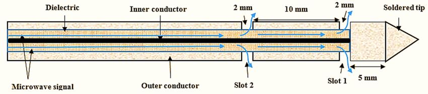
Ayo Z Ibitoye et al: Antennas for microwave ablation of liver                                           Pol J Med Phys Eng 2021;27(1):109-117

Figure 1. Schematic diagram of typical dual-slot antenna design. Two antennas A and B were simulated and fabricated from coaxial cables
of different thicknesses but the same prototype and dimensions shown in the figure.

need to develop an antenna that can withstand high power input              polytetrafluoroethylene (PTFE) while the outer shield was
for a long duration without damaging it. The antenna must also              made from a bare copper tube. The geometries and prototype
exhibit a reduced backward heating effect to preserve sensitive             of the simulated antennas are shown in Figure 1. These semi-
organs along the antenna insertion path.                                    rigid coaxial cables were chosen for this study to match the N-
   Computer modelling, which has played a crucial role in                   type connector of a microwave generator available in our
designing suitable antennas in the field of microwave                       laboratory. Dual slot antenna was chosen in this study because
technology, is being used to achieve the aforementioned                     it has been reported as having the ability to localize microwave
objective. Computer simulation is a quick, convenient and                   energy in the liver without additional metallic sleeve or choke
inexpensive tool for evaluating, isolating, and optimizing of               compared to other antennas.14,25
promising devices for prototyping.19-24 It is also an effective                Radiofrequency and heat modules in the software were used
method in understanding the interactions between microwave                  to study microwave energy distributions in the liver tissue and
energy and biological tissues. Finite element method (FEM)                  the bio-heat effects.26 The axially symmetric model was used to
and finite-difference time-domain (FDTD) has been adopted in                minimize the computation time while maintaining excellent
the antennas’ geometry specifications and evaluation of heat                resolution and the full 3-D nature of the fields. The electric and
transfer resulting from interactions of the microwave with                  magnetic fields associated with the time-varying transverse
biological tissues. Theoretically, microwave energy                         electromagnetic (TEM) wave generated by the microwave
propagation and absorption energy in tissue is governed by                  source propagating in a coaxial cable in the z-direction is
Maxwell’s equations while Pennes’ bio-heat equation governs                 expressed in 2-D axially symmetric cylindrical coordinates as
the temperature profile in tissue during ablation and these have            in Equations 1-4.
been discussed extensively in the literature.19-20 To establish the
study’s validity, an experimental validation method that                         =                                                       Eq. 1

                                                                                    =
includes fabrication of the antenna from the selected coaxial
                                                                                                                                         Eq. 2
cables, ex vivo experimentation and analysis of the obtained
                                                                                                                       "
data must be compared with the simulation results. Thus, in                     =       %
                                                                                                    ×    2   ! =           #$   %
                                                                                                                                         Eq. 3
                                                                                        &                                       &
this study, we employed computer simulation and experimental
                                                                                              )&*
validation methods to evaluate the efficiency of two antennas               with ' = (         /0
                                                                                                                                         Eq. 4
fabricated from different semi-rigid coaxial cables meant for                          +.-.         &

microwave ablation therapy.                                                 where E is the electric field (V m-1), H is the magnetic field
                                                                            strength (A m-1), 1 and 2 are the dielectric’s inner and outer
Materials and Methods                                                       radii, respectively (m), Pin is the input power (W), Z is the
                                                                            wave impedance in the dielectric of the coaxial cable (Ω), z is
Design and Simulation of Antennas
                                                                            the direction of propagation, and r, ϕ, and z are cylindrical
Finite element methods (FEMs) package in COMSOL
                                                                            coordinates centred on the axis of the coaxial cable.        is the
Multiphysics v 4.4 (Stockholm, Sweden) software was used to
                                                                            time-averaged power flow in the cable, and ω denotes the
                                                                            angular frequency. The propagation constant, 3 = 2 /5, and λ
design and simulate antennas A and B from semi-rigid coaxial
cables of 025″ (6.35 mm) and 0.085″ (2.21 mm) in diameters
                                                                            is the wavelength in the medium. In tissue, the electric field has
respectively. The software has the facilities for geometry
                                                                            a finite axial component (r) whereas the magnetic field is
specifications, studying heat transfer as a result of
                                                                            purely in the azimuthal direction (z). Thus, the antennas were
electromagnetic field distribution in the biological tissues.
                                                                            modelled using an axisymmetric transverse magnetic (TM)
Parameters such as ablation size, ablation shape, power
                                                                            formulation.
deposited into the tissue, temperature profile, necrosis
                                                                               The most significant effect of an electromagnetic field
parameter, power reflection coefficient, specific absorption rate
                                                                            applied is the conversion of microwave energy to thermal
(SAR) were predicted with the aid of this software. The inner
                                                                            energy. The temperature profile in tissue during ablation is
conductor of the coaxial cables was made from silver-covered
                                                                            obtained by solving a Pennes’ bioheat Equation 5:
copper and dielectric material made from a solid

                                                                      110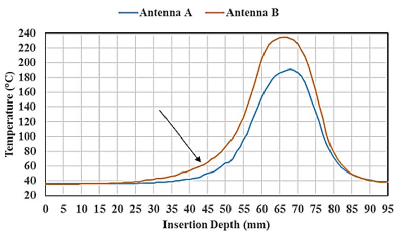
Ayo Z Ibitoye et al: Antennas for microwave ablation of liver                                     Pol J Med Phys Eng 2021;27(1):109-117

     89
67        = ∇ ∙ 3∇< + > − >@ + >A                           Eq. 5          maximum element size of 3 mm and the Lagrange quadratic
     8
                                                                           was used to approximate microwave power absorbed. The
where 6 (kg/m3 ) is the tissue density, c (J/kg·k) is the specific         external surface of the tissues acts as a boundary for the
heat of the tissue, k (W/mK) is thermal conductivity, T (K) is             computational domain. A low reflecting boundary was
the temperature, Q (W/m3) is the absorbed electromagnetic                  thermally isolated. Metallic components were assumed to be
energy, >@ (W/m3) is the heat loss due to microvascular blood              perfect electric conductors (PEC) and the coaxial dielectric was
perfusion, and >A (W/m3) is the metabolic heat generation.                 assumed to be lossless PTFE. Perfectly matched layers were
Generally, >A is ignored, as its magnitude is substantially                assumed for all exterior boundaries. Input power was set to 50
smaller than other terms in this equation. The absorbed                    W at 2.45 GHz in all the simulations. Electric field,
electromagnetic energy, Q, is computed from the                            temperature, necrosis, SAR distributions were computed and
electromagnetic field distribution in tissue and is given as:              analysed for all the tissues. The power reflection coefficient

> = 102 C|E|
                                                                           and power dissipation into the tissue were also quantified. The
                                                            Eq. 6
                                                                           lesion size and shape were calculated using the 52.0°C
When normalized by tissue density, 6, Q is referred to as                  isothermal contours after 10 min with an input power of 50 W,
specific absorption rate (SAR) therefore Equation 5 can be                 since, at this temperature coagulation and cell death are
rewritten as:                                                              possible.
     89
67        = ∇ ∙ 3∇< − >@ + FG + >A                          Eq. 7
     8                                                                     Experimental validation
Thermal damage due to heating is a function of the degree of               Microwave energy was delivered by using a 2.45 GHz solid-
temperature elevation, tissue properties, ablation duration and            state microwave generator (SAIREM SAS, Neyron-Cedex,
configuration of the applicator (antenna) used to deliver the              France), which has adjustable features for the input powers and
microwave energy. A fraction of necrotic tissue (thermal                   time. Ex vivo experimentation was performed on the bovine
injury), ɸ, is expressed as:                                               liver tissue obtained from a local abattoir. Semi-rigid coaxial
ɸ= 1−             I J
                                                            Eq. 8          cables RG401/U and RG405/U (Pasternack Enterprise Inc,
                                                                           Irvine) of 0.25″ (6.35 mm) and 0.085″ (2.21 mm) in diameters
where Ω(t) is the survival fraction of cells in tissue exposed to
                                                                           for the antennas A and B respectively were used. Antennas A
elevated temperature as:
                                                                           and B were fabricated from 50 Ω semi-rigid coaxial cables to
                           PQ
Ω L =        T
                 G MN O         S !L                        Eq. 9          conform to the geometrical specifications described in the
                          R9
                                                                           simulated method section (Figure 1). Fifteen bovine liver
Where A (1/s) is the frequency factor, Ea (J/mol) is the                   samples were ablated using the input power of 50 W for 3, 5
activation energy required to transform tissue from normal to              and 10 minutes using these antennas. Based on our previous
damaged state, R (J/mol·k) is the universal gas constant and T             experience, semi-rigid coaxial cables could withstand input
(k) is the absolute temperature of the tissue.                             power of about 50 W for a long duration for effective ablation
   The tissue was modelled geometrically as a cylinder of 50               without damaging the applicator. Five ablation processes were
mm by 95 mm height and assumes to be homogeneous. The                      conducted for the input power and ablation duration. After the
liver’s properties were taken from the literature and compared             ablation procedure, each tissue was sliced along the axis of the
with the software built-in values.27,28 The horizontal z-axis was          antenna to evaluate maximum dimensions of the coagulation
oriented along the longitudinal axis of the antenna and the                region in axial and radial cross-section after 3 hours. Ablation
vertical r-axis was oriented along the radial direction.                   diameter, ablation length and aspect ratio were physically
   In the electromagnetic wave propagation analysis, the                   measured with a highly accurate graduated ruler. Sliced ablated
scattering boundary condition was set on the surface, which                tissues were also captured by a high-resolution camera for
means that the boundary does not disturb the electromagnetic               further analysis. For all the ablated tissue; ablation lengths,
field distribution. The microwave signal was set at the upper              ablation diameters and sphericity indices were computed. The
end of the antenna (a dielectric component of the coaxial                  sphericity index was calculated from the quotient of r12 and r22.
cable). The microwave energy propagating in each antenna was               Where r1 and r2 are the radii of short and long- axis of the
characterized by transverse electromagnetic fields while                   ablated tissue respectively.29-30
transverse magnetic fields in tissue. No phase change occurs,                 ImageJ software from National Institute of Health (NIH,
no energy exchange through the outer surface and no chemical               USA) was used for the analysis of images generated from
reactions occur within the tissue.                                         simulation and experimental validation. A student’s t-test was
The model uses a frequency-domain problem formulation with                 used to compare the statistically significant difference between
the complex-valued azimuthal component of the magnetic field               the antennas. A value of p < 0.05 was considered to be
as the unknown. The asymmetric finite-element model was                    statistically significant.
discretized using the adaptive triangular element with a

                                                                     111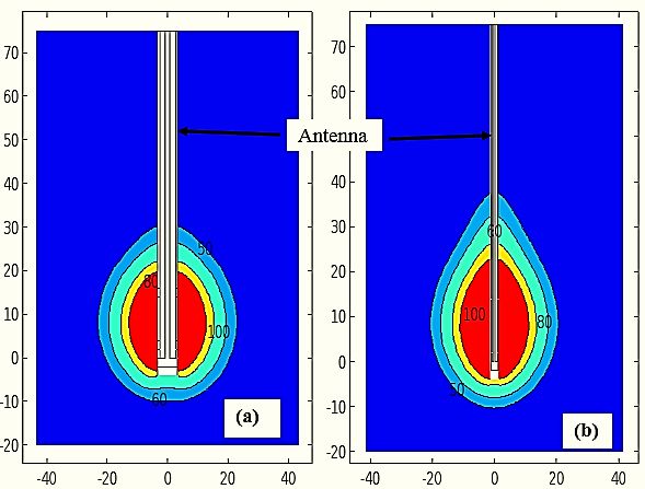
Ayo Z Ibitoye et al: Antennas for microwave ablation of liver                                        Pol J Med Phys Eng 2021;27(1):109-117

Results and Discussion                                                    Table 1. Simulation results produced by antennas A and B

Simulation Results                                                        Parameter                         Antenna A       Antenna B % difference
                                                                          Reflection Coefficient (dB)          -7.1             -6.1            -16.4
The simulation results using dual-slot antennas designed from
                                                                          Power deposited density (W)          39.5             36.8             7.3
different semi-rigid coaxial cables are presented in Table 1 and          Max Temp (@10 min) °C               191.8            227.1            -15.5
Figures 2-4.                                                              Max SAR (kW/kg)                       6.1             11.1            -45.0
   Table 1 shows the obtained values from simulation                      Short-axis (mm)                     39.0a            38.6c            13.0e
                                                                                                                    b               d
procedures using thick antenna A and thin antenna B from                  Long-axis(mm)                       43.6             46.4            -15.9f
                                                                          Sphericity index                     0.80             0.69             15.9
different coaxial cables. From the table, the reflection
                                                                          a = ablation length of antenna A, b = ablation diameter of antenna A,
coefficient was decreased by 16.4% when using antenna A
                                                                          c = ablation diameter of antenna B, d = ablation length of antenna B,
compared with the existing antenna B. This is an indication               e = % difference in the ablation diameters, f = %difference in the ablation
that antenna A exhibits better impedance matching with the                lengths
liver tissue than antenna B tissue. Power deposition was also
increased by 7.3% as a result of the low reflection coefficient.
Maximum temperature which could have resulted in excessive
heating of the coaxial cable was reduced by 15.5%. Based on
these results, antenna A has the higher potential of heating
tissue using high input powers without generating excessive
heat that will have negative effects on the performance of the
antenna. Antenna A has its SAR reduced by 45.0%. This
significant percentage difference may be assumed to be
connected to the excess SAR along the shaft of antenna B
which results in the generation of heat along its track. Ablation
length along the antenna shaft in antenna A was reduced by
15.9% when compared with antenna B. This is an indication
that antenna A can reduce backward heating along the antenna              Figure 2. Variations in temperature versus insertion depth from
shaft during the MWA procedures. Where tissue preservation                the proximal end of the antennas. The arrow in the figure
is necessary along the antenna shaft is expedient, antenna A              indicates that antenna A produced less backward heating than
will also be more suitable than antenna B. Ablation diameter              antenna B due to reduced temperature generated during the
(short-axis) of antenna A increased by 13.0% in comparison                microwave ablation procedure. Antenna B produced higher
with antenna B. As a result of this, tumours of larger diameters          temperatures at the depths beyond 25 mm than the antenna A.
or localized tumours bigger than 4 cm can be ablated with
antenna A better than antenna B. The sphericity index of
antenna A was 15.9% more than that of antenna B. This
signifies an increase in the localization of microwave energy at
the tip of antenna A than antenna B.
   Figure 2 shows a variation of temperature distribution versus
insertion depth using the input power of 50 W for 10 minutes.
The peak temperature difference between the antennas at the
depth of 67 mm from the proximal end of the antennas was
about 44°C with the antenna B produced 235°C. A reduced
temperature at the surface of antenna A shows its potential
application to preserve normal tissue at its point of insertion
during ablation procedures. In Figure 3, temperature
distributions at different isothermal levels are presented.
Backward heating along the shaft of the antenna A is more
reduced than antenna B at different temperature levels.                   Figure 3. Isothermal distributions in ablated tissue in (a)
                                                                          produced by antenna A and (b) produced by antenna B. The
                                                                          shape of the isothermal distribution produced at different
                                                                          temperatures in (a) is more spherical than those in (b). Backward
                                                                          heating along the antenna shaft was lowered in (a) than (b).

                                                                    112
Ayo Z Ibitoye et al: Antennas for microwave ablation of liver Pol J Med Phys Eng 2021;27(1):109-117
Figure 4 shows 3-D necrotic regions and the corresponding brittle which indicates a high degree of cell death and char; the
isothermal temperature contours (52.0°C) at which the middle zone appeared pink with coagulated indications and the
probability of cellular destruction is 63%.8 As shown in the outer appeared brighter at the boundary between the coagulated
figure, antenna A produced more localized microwave energy part and unaffected part. The size and colour of the ablated
than antenna B, therefore, making it (Antenna A) capable of zones depend on the type of the antenna, applied input power,
destroying tumours that display spherical morphology. and ablation duration. In the figure, (a) charred region is less
conspicuous when compared with (b). This may be as a result
Experimental results of a moderate temperature distribution around antenna A. This
Fifteen ablations were performed on bovine liver tissue ex vivo also resulted in a reduction in backward heating along the
using an input power of 50 W for 3, 5 and 10 minutes. Ablated antenna shaft because the copper material which made up the
ex-vivo bovine liver tissues are presented in Figure 5. On the outer part of the antenna helped to conduct excessive heat
pathologic inspection of coagulated regions, different degrees generated during the ablation procedures.
of ablation were noted. The inner zone appears pale, dark and
Figure 4. 3-D necrotic regions produce by antenna A and antenna (B) with the corresponding temperature. The black line on each figure
denotes a temperature of 52 °C which is equivalent to the ablated region and where the probability of dead is more than 63%. Sphericity
index is higher in (a) than in (b) based on necrotic region produced.
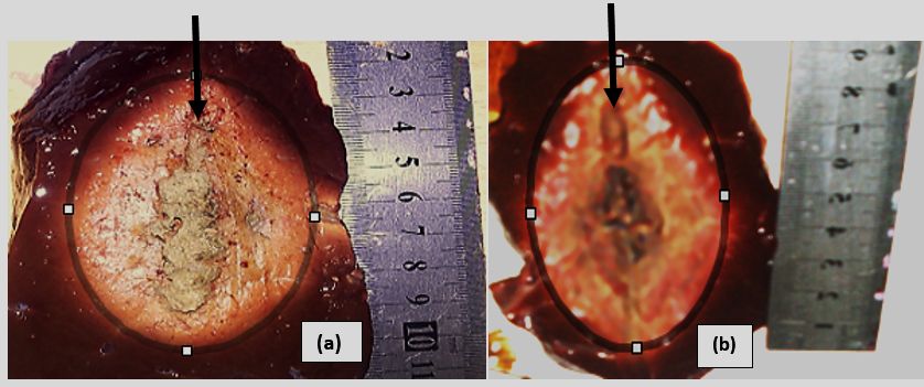
Figure 5. Ex-vivo ablated bovine liver tissues produced (a) by antenna A and (b) by antenna B with an input power of 50 W for 10 minutes.
The black lines in the diagrams define the ablated regions. Lesion produced in (a) was about 4.7 by 4.1 cm while 4.9 by 3.8 cm in (b) with
sphericity indices 0.76 and 0.60 respectively. The black arrows on the top of the figures are the point of insertion of the antennas.
113Ayo Z Ibitoye et al: Antennas for microwave ablation of liver Pol J Med Phys Eng 2021;27(1):109-117
Generally, ablation diameters of coagulated regions increase
with the duration of procedures as shown in Figure 6. Antenna
A produced a larger ablation diameter than antenna B at
different durations. On average, antenna A produced an
ablation diameter of approximately 7.1% more than that of
antenna B. Significant difference was also observed between
the ablation diameter of the two antennas (p = 0.04). In
Figure 7, the ablation length increased as the ablation duration
increases. On average, antenna A produced a reduction of 3.9%
in ablation length than Antenna B. This shows that Antenna A
has the potential of decreasing backward heating along the
antenna shaft by 3.9%. Also, a significant difference exists
between the ablation lengths of the two antennas (p = 0.02). In
Figure 8, antenna A produced more localized microwave
energy with high sphericity index than antenna B. On average,
antenna A produced 24.2 % in sphericity index more than
antenna B. Also, a significant difference exists between the
sphericity indices of the two antennas (p = 0.02). Figure 6. Ablation diameter variation versus ablation duration by
Table 2 shows a summary of simulated and experimental antennas A and B. Increase in ablation duration increases
results. From the table, there is no significant difference ablation diameter. At each duration Antenna A produces ablated
between the experimental and simulated results for antenna A diameter greater than the antenna B.
(p = 0.94) and antenna B (p = 0.98). The percentage differences
between the two parameters are also depicted in the table.
Figure 7. Ablation length versus ablation duration by antennas A Figure 8. Sphericity index versus ablation duration produced by
and B. The lengths of the ablated regions created along the antennas A and B. Antenna A created a lesion with high sphericity
antenna A longitudinal axis are generally greater than that index than antenna B. Ablation duration and types of the antennas
produced by antenna B which varies with ablation duration. determined the shape and size of the coagulative regions produced.
Table 2. Comparison between simulated and experimental validation results using the input power of 50 W for 10 minutes
Antenna A Antenna B
Parameter
Experiment Simulation %difference Experiment Simulation %difference
ablation Diameter (mm) 40.7 39 4.4 38.3 38.6 0.8
ablation length (mm) 46.7 43.6 7.1 49 46.4 5.6
Sphericity index 0.76 0.80 5.0 0.61 0.69 11.6
p-value 0.94 0.98
114Ayo Z Ibitoye et al: Antennas for microwave ablation of liver Pol J Med Phys Eng 2021;27(1):109-117
This paper describes the efficiency of two antennas designed power return loss is still a major concern.17 The findings in this
and fabricated from different 50 Ω semi-rigid coaxial cables study show that antenna fabricated from a thick coaxial cable
using numerical simulation and experimental validation can withstand high temperature without posing detrimental
methods for microwave ablation tumours. The findings from effects on the adjacent normal tissues. Ablation of tissue with a
the study show that antenna A with a thickness of 0.25′ (6.35 less charred region (Figure 5) is a piece of evidence that the
mm) produced better localization of microwave energy in the newly developed antenna can withstand high input power.
liver than antenna B of diameter 0.085’ (2.21 mm) (Figures 4 Also, where ablation diameters exceeding 4.0 cm is required
&5). Besides, antenna A created a reduced backward heating with high sphericity index and high reduction of backward
and higher ablation diameter and sphericity index than antenna heating antenna A can be used (Figures 6-8). Besides, antenna
B. Microwave energy is always delivered through an antenna A has the potential to be used where sensitive tissues or
which is a function of its diameter, composite materials, and organs-at-risk preservation are necessary. Research is still
impedance matching between the tissue and the antenna. The ongoing to establish the efficacy of clinical applications of
findings in this study also show that there is no significant microwave ablation technique in the management of tumours
difference between simulation and experimental validation in different organs.30,33 A robust antenna to deliver appropriate
results (Table 2). The percentage difference in the ablation energy during a microwave ablation procedure is desirable.
lengths, ablation diameters and sphericity indices are also The choice of an antenna and its application for microwave
minimal. This also is in agreement with the previous studies ablation therapy always depend on clinical indications such as
that computer modeling plays a major role in predicting tumor size, tumor location, adjacent organ and tumor
microwave energy distribution during microwave ablation morphology. According to this study, the thick antenna will
procedures.2,11-22 The applied frequency of the microwave have clinical applications where open surgical approaches are
propagating through an antenna and the applied input power is needed despite its larger diameter than the existing ones. More
also vital parameters that determine heat distribution pattern in also, antenna developed from thick semi-rigid coaxial cables
the ablated tissue. Currently, interstitial microwave antennas will be an excellent applicator to ablate large tumour volume
for percutaneous application are between 1.5 and 2.5 mm in with mild temperature with the assurance of preserving
diameter. Small diameter coaxial cables have been reported to adjacent normal organs. In vivo experimentation will be needed
have poor handling power leading to poor performance and to establish the performance of thick antenna to ablate tumour
heat generation along the antenna shaft.17 Antenna prototypes in the liver efficiently since our study was based on simulation
and geometries also play a major role in the localization of and experimental validation methods using ex vivo bovine
microwave energy apart from the complex anatomical structure liver.
of an ablated tissue.20 Antennas such as monopole, dipole,
dual-slot, single-slot, helical and dipole antennas designed and Conclusion
fabricated from a semi-rigid coaxial cable of diameter 0.085″
The findings in this study show that microwave power
for MWA are still hindered by some reported shortcomings in
distribution during microwave ablation of biological tissue is
the literature.15 Antennas, for example, dipole12 and dual-slot21
affected by antennas’ thicknesses. Antennas fabricated from
have been optimized by the addition of a floating metallic to
thick semi-rigid coaxial cables have a higher potential of
reduce their backward heating and improve their ability to
localizing microwave energy during microwave ablation of the
localize microwave energy into liver tissue. The use of coolant
liver than the existing ones. Also, the thick antenna provides a
with the antenna to reduce backward heating and improve
larger ablation diameter, higher sphericity index and higher
localization of microwave energy has been proposed.31-32 One
tendency of reducing backward heating along the antenna shaft
of the weaknesses of using coolant in reducing backward
than the existing antennas. In conclusion, antenna fabricated
heating is its potential to absorb microwave energy thereby
from thick coaxial cables will have clinical applications where
leading to less energy deposition into the tissue during
the mild temperature will be required using high input powers
microwave ablation. The addition of metallic sleeves on these
for long durations and around organ-at-risks where normal
antennas has to an extent reduced backward heating associated
tissue complication probability must be very low.
with them without a sleeve or choke.12,21 The ability of these
antennas to withstand high input power with minimal radiative
References
1. Ahmed M, Brace CL, Lee FT Jr, Goldberg SN. Principles of and advances in percutaneous ablation. Radiology. 2011;258(2):351-69.
https://doi.org/10.1148/radiol.10081634
2. Ryan TP, Brace CL. Interstitial microwave treatment for cancer: historical basis and current techniques in antenna design and
performance. Int J Hyperthermia. 2017;33(1):3-14. https://doi.org/10.1080/02656736.2016.1214884
115Ayo Z Ibitoye et al: Antennas for microwave ablation of liver Pol J Med Phys Eng 2021;27(1):109-117
3. Healey TT, March BT, Baird G, Dupuy DE. Microwave Ablation for Lung Neoplasms: A Retrospective Analysis of Long-Term
Results. J Vasc Interv Radiol. 2017;28(2):206-211. https://doi.org/10.1016/j.jvir.2016.10.030
4. Maciolek KA, Abel EJ, Best SL, et al. Percutaneous microwave ablation for local control of metastatic renal cell carcinoma. Abdom
Radiol (NY). 2018;43(9):2446-2454. https://doi.org/10.1007/s00261-018-1498-z
5. Izzo F, Granata V, Grassi R, et al. Radiofrequency Ablation and Microwave Ablation in Liver Tumors: An Update. The Oncologist.
2019;24(10):e990-e1005. https://doi.org/10.1634/theoncologist.2018-0337
6. Meloni MF, Chiang J, Laeseke PF, et al. Microwave ablation in primary and secondary liver tumours: technical and clinical
approaches. Int J Hyperthermia. 2017;33(1):15-24. https://doi.org/10.1080/02656736.2016.1209694
7. Zhou W, Zha X, Liu X, et al. US-guided percutaneous microwave coagulation of small breast cancers: a clinical study. Radiology.
2012;263(2):364-73. https://doi.org/10.1148/radiol.12111901
8. Ierardi AM, Biondetti P, Coppola A, et al. Percutaneous microwave thermosphere ablation of pancreatic tumours. Gland Surg.
2018;7(2):59-66. https://doi.org/10.21037/gs.2017.11.05
9. Fan QY, Zhou Y, Zhang M, et al. Microwave ablation of malignant extremity bone tumors. Springerplus. 2016;5(1):1373.
https://doi.org/10.1186/s40064-016-3005-8
10. Simon CJ, Dupuy DE, Mayo-Smith WW. Microwave ablation: principles and applications. Radiographics. 2005;25:S69-83.
https://doi.org/10.1148/rg.25si055501
11. Bertram JM, Yang D, Converse MC, et al. Antenna design for microwave hepatic ablation using an axisymmetric electromagnetic
model. Biomed Eng Online. 2006;9:1-9. https://doi.org/10.1186/1475-925X-5-15
12. Yang D, Bertram JM, Converse MC, et al. A floating sleeve antenna yields localized hepatic microwave ablation. IEEE Trans
Biomed Eng. 2006;53(3):533-7. https://doi.org/10.1109/TBME.2005.869794
13. Luyen H, Hagness SC, Behdad N. A balun-free helical antenna for minimally invasive microwave ablation. IEEE Trans Antennas
Propag. 2015;63:533-65. https://doi.org/10.1109/TAP.2015.2389223
14. Brace CL. Dual-slot antennas for microwave tissue heating : Parametric design analysis and experimental validation. Med Phys.
2011;38(7):4232-4240. https://doi.org/10.1118/1.3601019
15. Bertram JM, Yang D, Converse MC, et al. A review of coaxial-based interstitial antennas for hepatic microwave ablation. Crit Rev
Biomed Eng. 2006;34:187-213. https://doi.org/10.1615/critrevbiomedeng.v34.i3.10
16. Ibitoye AZ, Orotoye T, Nwoye EO, Aweda MA. Analysis of efficiency of different antennas for microwave ablation using simulation
and experimental methods Egypt J Basic Appl Sci. 2018;5:24–30. https://doi.org/10.1016/j.ejbas.2018.01.005
17. Brace CL. Microwave Tissue Ablation: Biophysics, technology, and applications. Crit Rev Biomed Eng. 2010;38(1):65-78.
https://doi.org/10.1615/critrevbiomedeng.v38.i1.60
18. Lubner MG, Brace CL, Hinshaw JL, Lee Jr FT. Microwave tumor ablation: Mechanism of action, clinical results, and devices. J
Vasc Interv Radiol. 2010;21:S192–S203. https://doi.org/10.1016/j.jvir.2010.04.007
19. Prakash P. Theoretical modeling for hepatic microwave ablation. Open Biomed Eng J. 2010;4:27-38.
https://doi.org/10.2174/1874120701004020027
20. Fallahi H, Prakash P. Antenna Designs for Microwave Tissue Ablation. Crit Rev Biomed Eng. 2018;46(6):495-521.
https://doi.org/10.1615/CritRevBiomedEng.2018028554
21. Ibitoye AZ, Nwoye EO, Aweda MA, et al. Optimization of dual-slot antenna using floating metallic sleeve for microwave ablation.
Med Eng Phys. 2015;37(4):384-91. https://doi.org/10.1016/j.medengphy.2015.01.015
22. Hand JW. Modelling the interaction of electromagnetic fields (10 MHz–10 GHz) with the human body: methods and applications.
Phys Med Biol. 2008;53(16):R243–R286. https://doi.org/10.1088/0031-9155/53/16/R01
23. Deshazer G, Prakash P, Merck D, Haemmerich D. Experimental measurement of microwave ablation heating pattern and comparison
to computer simulations. Int J Hyperthermia. 2017;33(1):74-82. https://doi.org/10.1080/02656736.2016.1206630
24. Chiang J, Wang P, Brace CL. Computational modelling of microwave tumour ablations, Int J Hyperthermia. 2013;29(4):308-317.
https://doi.org/10.3109/02656736.2013.799295
25. Chiang J, Hynes K, Bedoya M, Brace CL. A dual-slot microwave antenna for more spherical ablation zones: Ex vivo and in vivo
validation. Radiology. 2013;268(2):382–389. https://doi.org/10.1148/radiol.13122128
26. COMSOL Multiphysics users’ guide. Electromagnetic module and heat transfer module, Version 4.4; www.comsol.com/models
27. Hasgall PA, Di Gennaro F, Baumgartner C, et al. IT’IS Database for thermal and electromagnetic parameters of biological tissues.
Version 4.0, May 15, 2018. Accessed 05 June 2019. https://doi.org/10.13099/VIP21000-04-0
28. Andreuccetti D, Fossi R, Petrucci C. An Internet resource for the calculation of the dielectric properties of body tissues in the
frequency range 10 Hz - 100 GHz. IFAC-CNR, Florence (Italy), 1997. Based on data published by C. Gabriel et al. in 1996. [Online].
Available: http://niremf.ifac.cnr.it/tissprop
116Ayo Z Ibitoye et al: Antennas for microwave ablation of liver Pol J Med Phys Eng 2021;27(1):109-117
29. Hines-Peralta AU, Pirani N, Clegg P, et al. Microwave Ablation: Results with a 2.45 GHz Applicator in vitro Bovine and in vivo
Porcine Liver. Radiology. 2006;239(1):94-102. https://doi.org/10.1148/radiol.2383050262
30. Ruiter SJS, Heerink WJ, de Jong KP. Liver microwave ablation: a systematic review of various FDA-approved systems. Eur Radiol.
2019;29(8):4026-4035. https://doi.org/10.1007/s00330-018-5842-z
31. Zhou W, Liang M, Pan H, et al. Comparison of ablation zones among different tissues using 2450-MHz cooled-shaft microwave
antenna: results in ex vivo porcine models. PloS One. 2013;8(8):e71873. https://doi.org/10.1371/journal.pone.0071873
32. Kuang M, Lu MD, Xie XY, et al. Liver cancer: increased microwave delivery to ablation zone with cooled-shaft antenna-
experimental and clinical studies. Radiology. 2007;242(3):914–924. https://doi.org/doi.10.1148/radiol.2423052028
33. Ibitoye AZ, Nwoye EO, Aweda MA, et al. Microwave ablation of ex vivo bovine tissues using a dual-slot antenna with a floating
metallic sleeve, Int J Hyperthermia. 2016;32(8): 923–930 https://doi.org/10.1080/02656736.2016.1211323
117You can also read