USER MANUAL ADVANTECH - Node Explorer
←
→
Page content transcription
If your browser does not render page correctly, please read the page content below
USER MANUAL

                                 ADVANTECH
                                 Node Explorer

                                                         Edition 6
                                                         May 2021

Copyright 2021 All rights reserved. Advantech Co. Ltd.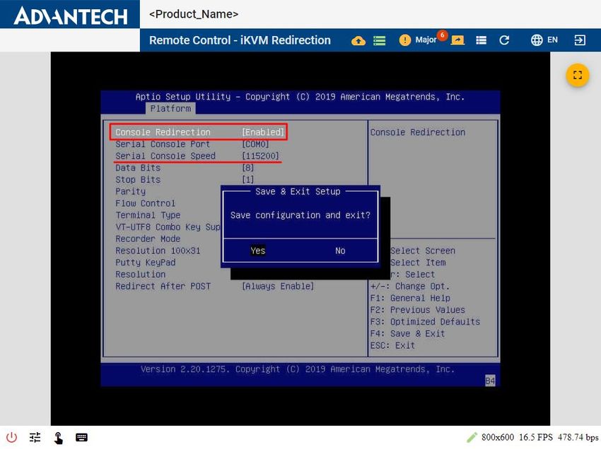
Revision History
 Document                 Document            Software Revision and Modifications
 Release Date             Revision
 05/07/2021               Edition 6.0         Official release
                                              Base on nodeexp-1.22.2
 04/21/2021               Edition 5.5         Base on nodeexp-1.22.2
                                              1. LDAP
                                                Configurations - extra configurations - LDAP
                                              2. RADIUS
                                                Configurations - extra configurations - RADIUS
                                              3. VNC Service
                                                Configurations - extra configurations – VNC Service
                                              4. Remote syslog
                                                configurations - extra configurations - remote syslog
                                              5. Added Load / Save BIOS configurations in
                                                   maintenance - configurations
                                              6. Supports output BMC debug log to Syslog
                                                configurations - maintenance - BMC debug log
                                              7. Host Screenshot
                                                configurations - maintenance - host screenshot
                                              8. BIOS setup
                                                remote control - BIOS setup
 04/14/2020               Edition 5.3         Based on noteexp-1.20.5
                                              1. Include BMC debug log in maintenance page.
                                              2. Refine the statements in remote storage.
 03/30/2020               Edition 5.0         Based on noteexp-1.20.5
                                              1. BIOS post code
                                                tool bar, remote control - system power control
                                              2. IPv6 default gateway
                                                configurations - network
                                              3. User permission (PAM module)
                                                configurations - extra configurations - user management
                                              - edit user
                                              4. CA certificate chain (customized feature)
                                                configurations - extra configurations - SSL certificate -
                                              upload SSL certificate
                                              5. Firewall (port, IPv4, IPv6) (customized feature)
                                                configurations - extra configurations - firewall
                                              6. BMC debug download (customized feature)
                                                configuration - maintenance - BMC debug log
                                              7. SSH key management (customized feature)
                                                configuration - extra configurations - SSH key
                                              management
                                              8. Session timeout
                                              configurations - extra configurations – session timeout
                                              9. Open remote serial console in new tab directly
                                              10.Supports display of instant sensor reading

Copyright 2021. All rights reserved. Advantech Co. Ltd.   Page 1
02/28/2019 Edition 4.0 Based on noteexp-1.18.8
PEF destination dialog: makes it easier to select and copy
text from replace word list
System power control
Show BIOS POST code in tool bar
BIOS Boot Option : Add BIOS support information
Remote storage
One-click connect/disconnect
11/23/2018 Edition 3.0 Based on noteexp-1.18.1
1. Added some useful notes
2. User experience improvement
3. New functionalities
- Supports simplified/traditional Chinese
- Information for multi-node system
- Maintenance page
Loads default/download/upload configuration
with encryption
Firmware upgrade check
Remote Control will be released in noteexp-1.19.0
More BIOS boot options in system power control
Front panel
Remote serial console
09/30/2018 Edition 2.0 New features in noteexp-1.17.4
- System health : advanced inventory, web alert
- Configuration : advanced setting of alerts, VLAN
Setting in network, NTP setting, user
management, network – Ipv6
- Extra configuration: Time sync, firmware
upgrade, SNMP
- Remote storage
Modify remote control – iKVM, login session timeout and
limitation
Adjust Advantech web layout, information in sensor
status
Login timeout is 1 week
09/29/2017 Edition 1.0 1st official release based on noteexp-1.15.0
Copyright 2021. All rights reserved. Advantech Co. Ltd. Page 2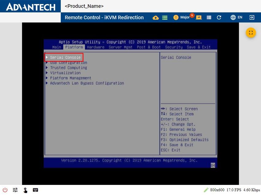
Table of Contents
1. NODE EXPLORER .................................................................................. 9
2. ACCESSING NODE EXPLORER ........................................................ 10
3. WEB PAGE INDEX .............................................................................. 12
3.1 TOOL BAR ......................................................................................................................... 12
3.2 OVERVIEW ........................................................................................................................ 13
3.3 SYSTEM HEALTH .............................................................................................................. 14
3.3.1 Advanced Inventory ......................................................................................................................... 14
3.3.2 Sensor Status ....................................................................................................................................... 14
3.3.3 Event Log .............................................................................................................................................. 17
3.3.4 Web Alert .............................................................................................................................................. 19
3.3.5 Session ................................................................................................................................................... 20
3.4 CONFIGURATION .............................................................................................................. 21
3.4.1 Alerts ....................................................................................................................................................... 21
3.4.1.1 Event Filter Table .............................................................................................................................. 22
3.4.1.2 Alert Policy Table .............................................................................................................................. 23
3.4.1.3 Destinations ......................................................................................................................................... 24
3.4.2 Network ................................................................................................................................................. 26
3.4.3 Extra Configurations ........................................................................................................................ 28
3.4.3.1 The User Management Tab ........................................................................................................... 28
3.4.3.2 The LDAP Tab ..................................................................................................................................... 29
3.4.3.3 The RADIUS Tab ................................................................................................................................ 29
3.4.3.4 The Time Tab ...................................................................................................................................... 30
3.4.3.5 The SSL Certificate Tab ................................................................................................................... 33
3.4.3.6 The SSH Key Management ............................................................................................................. 35
3.4.3.7 The SMTP (Simple Mail Transfer Protocol) Tab .................................................................. 36
3.4.3.8 The SNMP (Simple Network Management Protocol) Tab ............................................... 37
3.4.3.9 The Session Timeout Tab............................................................................................................... 38
3.4.3.10 The Firewall Tab ........................................................................................................................... 39
3.4.3.11 The VNC Service Tab ................................................................................................................... 40
3.4.3.12 The Remote Syslog Tab ............................................................................................................. 41
3.4.4 Maintenance ........................................................................................................................................ 42
3.4.4.1 The Version Tab ................................................................................................................................. 42
3.4.4.2 The Configuration Tab .................................................................................................................... 42
3.4.4.3 The Firmware Upgrade Tab ......................................................................................................... 50
3.4.4.4 The BMC Debug Log Tab ................................................................................................................ 53
3.4.4.5 The Host Screenshot Tab ............................................................................................................... 54
3.4.5 BMC Interface control ..................................................................................................................... 55
3.5 REMOTE CONTROL SESSION ........................................................................................... 56
3.5.1 System Power Control..................................................................................................................... 56
3.5.2 Front Panel ........................................................................................................................................... 59
3.5.3 iKVM Redirection .............................................................................................................................. 60
3.5.3.1 iKVM functionality ............................................................................................................................ 61
3.5.3.2 Remote Storage .................................................................................................................................. 63
Via Windows File Share (SMB) ................................................................................................................ 63
Via Web .............................................................................................................................................................. 67
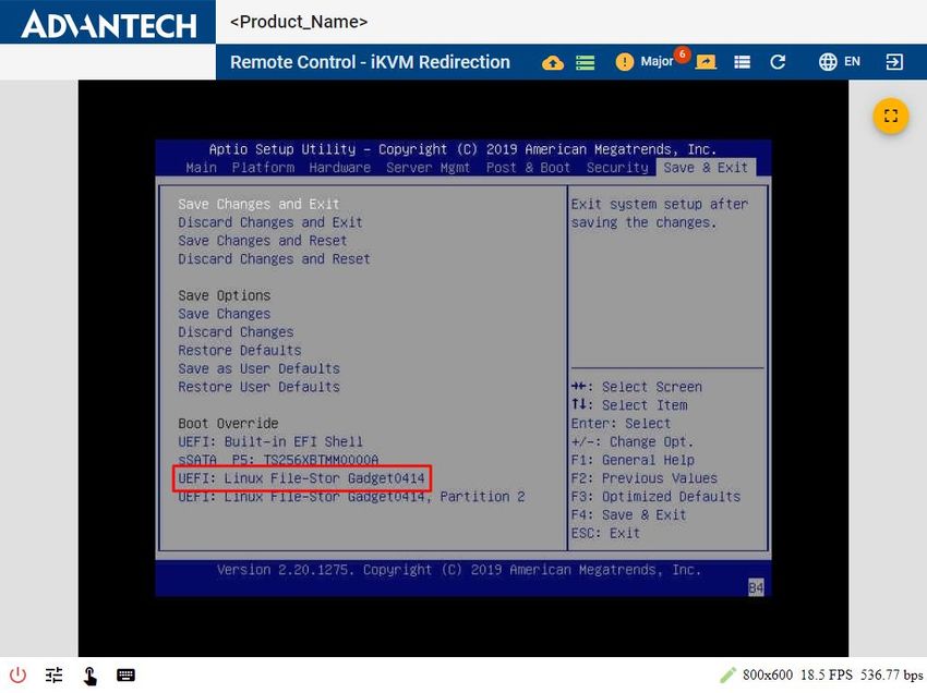
After Mounting Remote Storage..................................................................................................................... 70
3.5.4 Remote Serial Console .................................................................................................................... 72
3.5.5 BIOS Setup ............................................................................................................................................ 76
Copyright 2021. All rights reserved. Advantech Co. Ltd. Page 3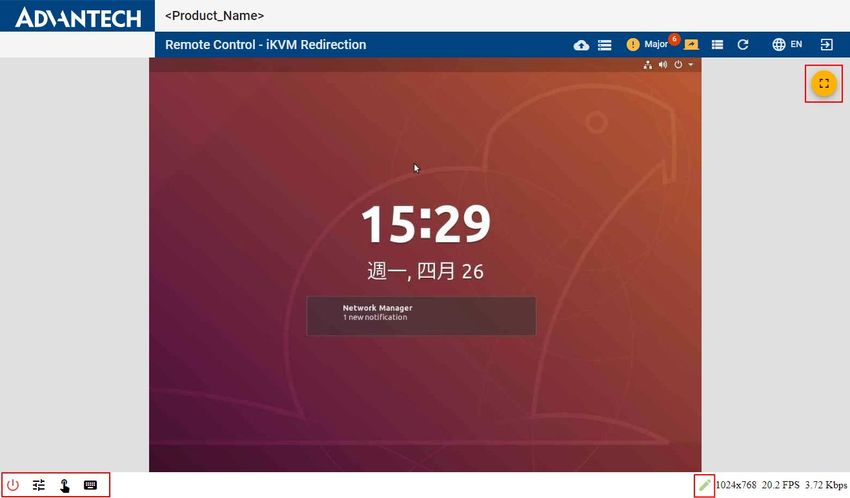
4.      TIPS AND TROUBLESHOOTING..................................................... 78
     4.1       WEB PAGE TIMEOUT....................................................................................................... 78
     4.2       SESSION LIMITATIONS..................................................................................................... 78
     4.3       SECURITY WARNING MESSAGE ...................................................................................... 78
     4.4       LOG OUT ........................................................................................................................... 79

Copyright 2021. All rights reserved. Advantech Co. Ltd.                Page 4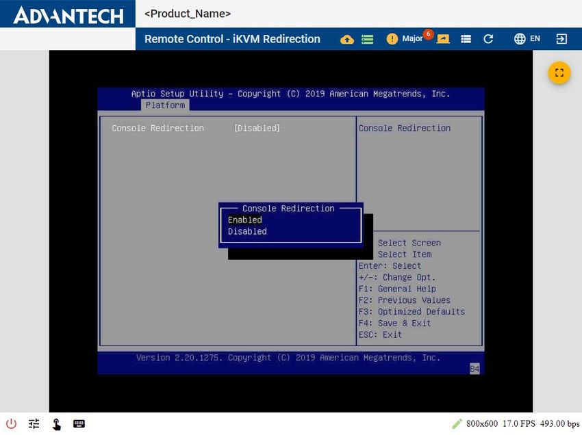
List of Figures
Figure 1: Login Page................................................................................................................. 11
Figure 2: Main Page after a Successful Login .......................................................................... 11
Figure 3: Overview Page .......................................................................................................... 13
Figure 4: Advanced Inventory page ......................................................................................... 14
Figure 5: Sensor Status Page ................................................................................................... 15
Figure 6: Sensor Status Indicating Alarm Levels and Crossed Thresholds .............................. 15
Figure 7: Plotted-Out History Curve for Downloading ............................................................ 16
Figure 8: Event Log Page.......................................................................................................... 17
Figure 9: Save Details as a .Json File ........................................................................................ 18
Figure 10: Web Alert Page ....................................................................................................... 19
Figure 11: Details in Event Log ................................................................................................ 19
Figure 12: Session List Page ..................................................................................................... 20
Figure 13: Session details ........................................................................................................ 20
Figure 14: Alerts Page .............................................................................................................. 21
Figure 15: Alert Setting Modification (Event Filter Table) ....................................................... 22
Figure 16: Alert Setting Modification (Alert Policy Table) ....................................................... 23
Figure 17: Destinations Settings (PET Trap) ............................................................................ 24
Figure 18: Destinations Settings (SMTP Email)........................................................................ 24
Figure 19: Destinations Settings (SMTP Email)........................................................................ 25
Figure 20: Network Page ......................................................................................................... 26
Figure 21: IPv6 information per LAN Interface........................................................................ 27
Figure 22: User Management Tab ........................................................................................... 28
Figure 23: LDAP Tab (Authentication via Remote LDAP Server) ............................................. 29
Figure 24 RADIUS Tab (Authentication via Remote RADIUS Server) ....................................... 29
Figure 25: Time Tab (System Time and NTP Settings) ............................................................. 30
Figure 26: Time Zone Successfully Set ..................................................................................... 31
Figure 27: Offsetting the System Time .................................................................................... 31
Figure 28: NTP Settings............................................................................................................ 32
Figure 29: SSL Certificate Tab .................................................................................................. 33
Figure 30: Upload SSL .............................................................................................................. 34
Figure 31: SSH Key Management Tab...................................................................................... 35
Figure 32: SMTP Tab ................................................................................................................ 36

Copyright 2021. All rights reserved. Advantech Co. Ltd.           Page 5
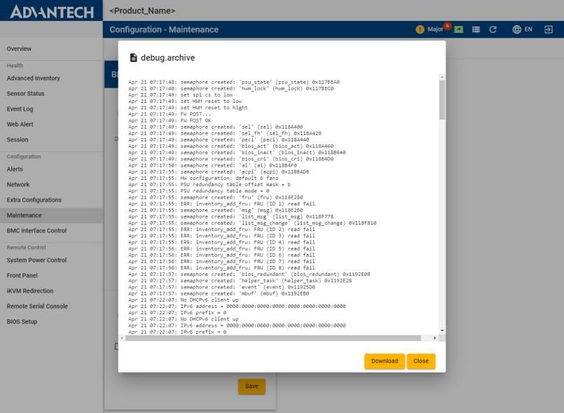
Figure 33: SNMP Tab ............................................................................................................... 37
Figure 34: Session Timeout Tab............................................................................................... 38
Figure 35: Session Timeout Success ........................................................................................ 38
Figure 36: Add Port Firewall .................................................................................................... 39
Figure 37: Add IPv4/IPv6 Address Firewall .............................................................................. 39
Figure 38: VNC Service Tab...................................................................................................... 40
Figure 39: TightVNC Viewer..................................................................................................... 40
Figure 40: Remote Syslog Tab ................................................................................................. 41
Figure 41: The Version Tab ...................................................................................................... 42
Figure 42: More Version Information on Other FW/SW ......................................................... 42
Figure 43: The Configuration Tab ............................................................................................ 43
Figure 44: Enter Your Password for Confirmation .................................................................. 43
Figure 45: Re-confirm Loading the Default Settings ............................................................... 44
Figure 46: Default Settings Successfully Loaded ..................................................................... 44
Figure 47: Encryption Key Popup ............................................................................................ 45
Figure 48: Check the Always Allow Button to Download Multiple File ................................... 45
Figure 49: Enter Login Password for Confirmation ................................................................. 46
Figure 50: Select File then Press Next to Upload Configuration File ....................................... 46
Figure 51: Uploading the Configuration File ........................................................................... 47
Figure 52: Enter the Encryption Key ........................................................................................ 47
Figure 53: Confirmation Failed ................................................................................................ 48
Figure 54: Confirmation of the Applied Update ...................................................................... 48
Figure 55: Applying the Configuration .................................................................................... 49
Figure 56: Configuration Successfully Applied ........................................................................ 49
Figure 57: Firmware Upgrade Tab ........................................................................................... 50
Figure 58: Firmware Image Uploading to the BMC ................................................................. 50
Figure 59: Confirmation of Upgrade........................................................................................ 51
Figure 60: Error Message during Upgrade .............................................................................. 51
Figure 61: Firmware Upgrade in Progress ............................................................................... 52
Figure 62: Firmware Upgrade Successful ................................................................................ 52
Figure 63: BMC Debug Log ...................................................................................................... 53
Figure 64: Check debug.archive .............................................................................................. 53
Figure 65: The Host Screenshot Tab ........................................................................................ 54
Figure 66: Reviewed Screenshot by One Click ........................................................................ 54

Copyright 2021. All rights reserved. Advantech Co. Ltd.          Page 6
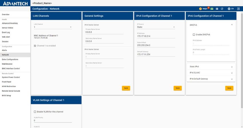
Figure 67: BMC Interface Control ............................................................................................ 55
Figure 68: Server Power Control Page..................................................................................... 56
Figure 69: BIOS POST Code History dialog............................................................................... 56
Figure 70: BIOS Boot Options are Saved ................................................................................. 57
Figure 71: Server Power Action Countdown ........................................................................... 58
Figure 72: Front Panel Page..................................................................................................... 59
Figure 73: Redirecting.............................................................................................................. 60
Figure 74: Pop-ups Were Blocked On This Page. .................................................................... 60
Figure 75: iKVM Screenshot Example: Graphic UI ................................................................... 60
Figure 76: iKVM Redirection Settings Buttons ........................................................................ 61
Figure 77: iKVM is Disconnected Because of Timeout or Shutdown ...................................... 62
Figure 78: Remote Storage functionality................................................................................. 63
Figure 79: Remote Storage Connected via SMB...................................................................... 64
Figure 80: Remote Storage (SMB) Successfully Mounted ....................................................... 65
Figure 81: Remote Storage (SMB) Mount Failed ..................................................................... 65
Figure 82: Remote Storage (SMB) Disconnected .................................................................... 66
Figure 83: The Remote Image (SMB) is Connected ................................................................. 66
Figure 84: Remote Storage (Web) ........................................................................................... 67
Figure 85: Selecting an Image File for Remote Storage (Web) ............................................... 67
Figure 86: Virtual Drive Successfully Mounted via Remote Storage (Web) ............................ 68
Figure 87: The Remote Image (Web) is provided by another Client ....................................... 68
Figure 88: Virtual Drive Disconnected ..................................................................................... 69
Figure 89: Restarting x86 Payload and Entering BIOS Setup Menu ........................................ 70
Figure 90: Restarting x86 Payload from Tool Bar and Entering BIOS Setup Menu ................. 70
Figure 91: Select Remote Storage in BIOS Setup Menu .......................................................... 71
Figure 92: Serial Console in BIOS Setup Menu ........................................................................ 72
Figure 93: Enable Serial Console in BIOS Setup Menu ............................................................ 73
Figure 94: Save Serial Console Configuration in the BIOS Setup Menu .................................. 73
Figure 95: Open Serial Console in Remote Serial Console Page.............................................. 74
Figure 96: Redirecting.............................................................................................................. 74
Figure 97: Remote Serial Console Page ................................................................................... 75
Figure 98: Open BIOS Setup Page ............................................................................................ 76
Figure 99: Asked for Username and Password in BIOS Setup Page ........................................ 76
Figure 100: BIOS Setup Page (BIOS Setup Web Utility) ........................................................... 77

Copyright 2021. All rights reserved. Advantech Co. Ltd.           Page 7
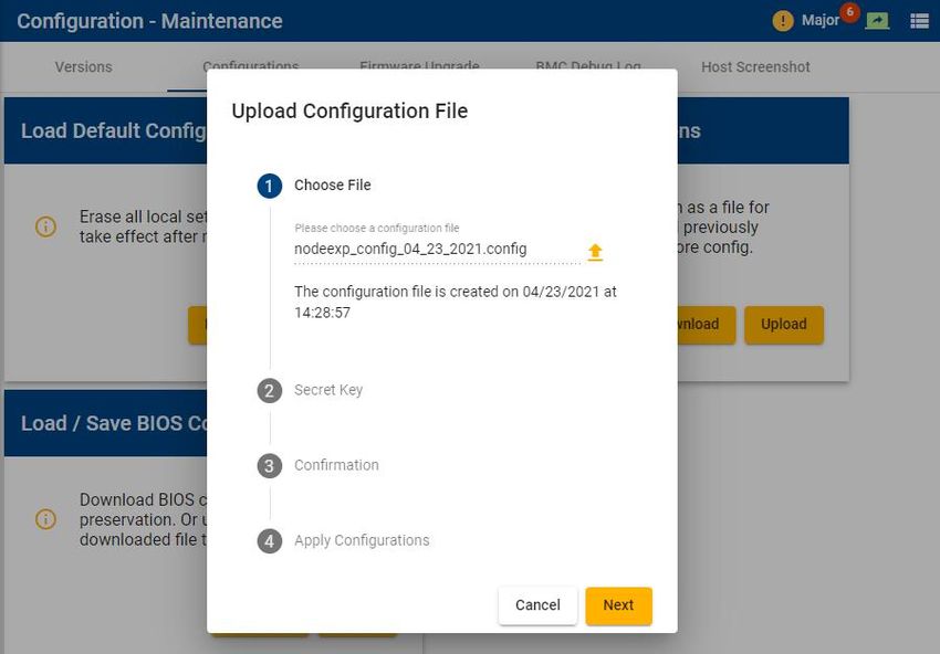
Figure 101: Security Warning Message ................................................................................... 78
Figure 102: Log Out ................................................................................................................. 79

Copyright 2021. All rights reserved. Advantech Co. Ltd.           Page 8
1. NODE EXPLORER
Node Explorer is a web-based interface that provides a simple approach for accessing the
BMC in order to manage and monitor the system’s health status. By default, the BMC’s Node
Explorer is enabled for Advantech’s Advanced Platform Management in Advantech’s server
series.
This node explorer (nodeexp) version can be checked in the version tab referred to section
3.4.4.1.
If you cannot find the information you are looking for or need more detailed information on
a specific topic, please refer to the list of additional documents and other sources of
information below. Please contact your Advantech representative if you need help obtaining
these documents or still cannot find what you are looking for.
Intelligent Platform Management Interface Specification, Version 2.0, Revision 1.1,
October 1, 2013-E7 April 21, 2015.
IPMI – Platform Management FRU Information Storage Definition, V1.0, Document
Revision 1.1, September 27, 1999.
IPMI - Platform Event Trap Format Specification V1.0, Document Revision 1.0,
December 7, 1998.
Information on Intel CPUs, chipsets and NIC silicon can be found at www.intel.com
Advantech Product User Manual and platform management User Manual
Copyright 2021. All rights reserved. Advantech Co. Ltd. Page 92. ACCESSING NODE EXPLORER
Perform the following steps to access Node Explorer:
Configure the BMC’s IP as desired (by default, it is set as static address 0.0.0.0). For
more details, please refer to the Advantech Advanced Platform Management User
Guide of each product.
Configure the IP of the remote computer and ensure that the remote computer’s IP
and the BMC’s IP are located in the same subnet. On the remote computer, start a
web browser (Google Chrome is used in our example) to access the BMC secure
website.
Type https:///nodeexp in the address bar, press Enter to go to the Node
Explorer login page. Node Explorer can be accessed via both IPv4 and IPv6
addresses.
Node Explorer comes with a default SSL Certificate; the browser might show a
warning about an invalid certificate, which must be accepted before Node Explorer
can be accessed.
The following web browsers have been verified with Node Explorer:
Firefox versions 45.0.1 or later
Chrome versions 49.0.2623.87 or later
Safari versions 9.0.5 or later
Copyright 2021. All rights reserved. Advantech Co. Ltd. Page 10Figure 1: Login Page
Use the default BMC LAN channel credentials (case-sensitive) for login:
User name: administrator
Password: advantech
Please note that it will require administrator privileges in order to access all the
functionalities of the web interface. The login session will timeout after 3600 x 24 x 7
seconds (1 week). In addition, you will need to login again after the IP address or web
browser has been changed, browser data cleared, or the BMC rebooted.
Upon successful login, the web interface overview will appear as shown in Figure 2.
Note: For security reasons, please change the user credentials after the first login.
Figure 2: Main Page after a Successful Login
Copyright 2021. All rights reserved. Advantech Co. Ltd. Page 113. WEB PAGE INDEX
The menu structure of Node Explorer might differ between revisions and depending on the
supported functionality.
3.1 Tool Bar
There are 4 icons located on the top-right corner of the web interface—same for all pages.
Alert status (refer to Figure 6 for detailed definition). Clicking the icon will
take you to the sensor status page. (Refer to 3.3.2 Sensor Status).
Host power status. This will be always updated whenever the alert status is
updated by clicking the refresh button or when navigating to a different page.
Clicking the icon will let you use the Power Control option, which is the same
as the System Power Control page (see 3.5.1 System Power Control for more
details).
Shortcut of BIOS POST code history. The dialog box for the BIOS POST code
will be pop out as Figure 69: BIOS POST Code History dialog in chapter 3.5.1
System Power Control.
Refreshes 3.3.2 Sensor Status, 3.3.4 Web Alert, Power Status and BIOS Post
Code in 3.5.1 System Power Control page.
Language selection supporting English, Simplified Chinese, Traditional
Chinese.
Log out.
Copyright 2021. All rights reserved. Advantech Co. Ltd. Page 123.2 Overview
General information of the BMC uptime and BMC boot-up time, firmware version
(Bootloader, BMC, BIOS, FPGA, BIOS, NVRAM), software version, and network setting for
each LAN channel.
The Network Information box provides quick access to the network configuration page.
Edit network configuration
Figure 3: Overview Page
On the Overview page, the hostname, address information and the node name at the top-
right side will be only visible in multi-node systems for node identification.
Copyright 2021. All rights reserved. Advantech Co. Ltd. Page 133.3 System Health
3.3.1 Advanced Inventory
The Health - Advanced Inventory page provides a simple way of accessing basic information
on the system hardware, including processors, memory, network adapters, fans, graphics
adapters, and other devices (e.g., disk drives).
Please note that the inventory of CPU, memory, storage, network, PSU, cooling, and FRU
need to be supported with the appropriate BIOS.
Figure 4: Advanced Inventory page
3.3.2 Sensor Status
The Sensor Status page provides the latest sensor readings of all system sensors.
The drop down menu located at the top of the sensor list can be used to filter preferred
sensor types:
Threshold-based All threshold-based sensors
Temperature sensors Lists only temperature sensors
Voltage sensors Lists only voltage sensors
Fan sensors Lists only fan sensors
All Lists all sensors
The instant reading for each sensor as shown in Figure 5: Sensor Status Page will be
displayed beside the sensor name after nodeexp-1.20.0.
Copyright 2021. All rights reserved. Advantech Co. Ltd. Page 14Figure 5: Sensor Status Page
The color and icon of the sensor status indicates the alarm level and crossed thresholds, as
shown in Figure 6.
ok Sensor reading is normal
warning Sensor reading has reached the upper/lower non-critical threshold
major Sensor reading has reached the upper/lower critical threshold
critical Sensor reading has reached the upper/lower non-recoverable
threshold
unknown No sensor reading
Note: The sensor readings will not be refreshed automatically. You must always reselect the
Sensor Status page in order to get the latest readings.
Figure 6: Sensor Status Indicating Alarm Levels and Crossed Thresholds
Copyright 2021. All rights reserved. Advantech Co. Ltd. Page 15After a sensor has been selected from the sensor list on the left side of the page, the sensor
information will be shown in three tabs.
Status
Status Sensor name, ID, entity, last reading, current status
Thresholds The thresholds are defined according to IPMI and BMC spec
Event List
Shows all logged events issued by the selected sensor
History chart
On the right of this page, the last 150 min (one reading per 5 min x 30) of historic sensor
readings for a single threshold-based sensor are presented as a curve. There will be no
historic curve for discrete sensors because they do not report a numeric reading. Clicking
Open in New Window icon on the top-right side of the history chart, will plot the curve,
which can be downloaded as a .PNG file (see Figure 7).
Figure 7: Plotted-Out History Curve for Downloading
Copyright 2021. All rights reserved. Advantech Co. Ltd. Page 163.3.3 Event Log
The Event Log page shows the system event log (SEL) of the platform. For each SEL entry, the
event ID, time stamp, sensor name, sensor type, and event description are displayed. The
number of displayed events per page can be adjusted by using the Items per page list at the
bottom-right corner of the page.
Figure 8: Event Log Page
Users can jump to next/previous/first/last page by clicking the navigation icons at bottom-
right corner of the page.
More operations can be opened by clicking the More options icon
Refresh the event list
Clear all events
Download the event list as .csv file
Copyright 2021. All rights reserved. Advantech Co. Ltd. Page 17Select an event to get more details (e.g., SEL name, sensor type, event code) and to
download the details as “JSON-File sel_.json”
Figure 9: Save Details as a .Json File
Copyright 2021. All rights reserved. Advantech Co. Ltd. Page 183.3.4 Web Alert
The web alert notification history of the platform is shown on this page. The displayed alerts
can be filtered by using the Level Filter (critical, major, warning), State Filter (all, checked,
new), and Sensor Type Filter. For each entry, the event ID, alarm level (see Figure 10),
sensor name, assertion time, desertion time, and read status are shown.
More operations can be opened by clicking the More options icon.
Refresh the list
Mark all alerts as read (the status will then change to )
Delete all past alerts
Figure 10: Web Alert Page
Figure 11: Details in Event Log
Copyright 2021. All rights reserved. Advantech Co. Ltd. Page 193.3.5 Session
The Session page is to show current user and user status. You can get the more user
information (e.g. user name, user level, log in time) by double clicking on the user items.
Figure 12: Session List Page
In addition, if the user opens iKVM or serial console session, it will be displayed in the
Attached Sessions in user list and the control button will be shown in pop-up Session Detail
dialog.
Figure 13: Session details
You can end any sessions by pressing the button and there will be a warning message
“Ending a session will cause unexpected results. Continue to end xxx session?” before the
session has ended. You can also end all node explore/iKVM/serial console sessions by
Copyright 2021. All rights reserved. Advantech Co. Ltd. Page 20pressing the button. Before all the sessions are ended, including node explorer, you
have to double confirm the warning message “The current session and all its associated
sessions will also be closed down. This page will then be logged out. Continue?”
3.4 Configuration
3.4.1 Alerts
This page allows you to set and modify the advanced alert settings via the following tabs:
Event Filter Table
Alert Policy Table
Destinations
Figure 14: Alerts Page
Copyright 2021. All rights reserved. Advantech Co. Ltd. Page 213.4.1.1 Event Filter Table
Each alert entry can be clicked to enable/disable the platform event filter (PEF), change the
policy number, adjust the severity, perform corresponding actions (alert or OEM action), set
a sensor type and name, and view detailed event information. Depending on the alert type,
further settings are available. For a definition of the event severity, refer to: “IPMI Platform
Event Trap Format Specification v2.0.”
Policy Number: [Policy number in Alert policy table]. The total number of policies with the
same policy number (i.e. how many policies are enabled). This can be set in the alert policy
table.
Figure 15: Alert Setting Modification (Event Filter Table)
Copyright 2021. All rights reserved. Advantech Co. Ltd. Page 223.4.1.2 Alert Policy Table
In the table, the alert policy can be enabled and the corresponding action can be selected
(e.g. [Always send], [Next entry], [Stop on success], etc.)
Enable/disable the alert policy: checking/clearing the box
Destination: [Channel – Destination ID] IP or [Channel – Destination ID] email
address is defined in the Destinations tab in the Alerts page
Policy: Different alert policy as described in Figure 16.
Figure 16: Alert Setting Modification (Alert Policy Table)
Copyright 2021. All rights reserved. Advantech Co. Ltd. Page 233.4.1.3 Destinations
Destination type: PET Trap or SMTP mail
Different settings regarding the network management protocol type: destination IP
or email receiver address, subject, and message body mail address
Note: Send Test button is important to check if the destination actually works. Check
SMTP setting if SMTP does not work.
Figure 17: Destinations Settings (PET Trap)
Figure 18: Destinations Settings (SMTP Email)
Copyright 2021. All rights reserved. Advantech Co. Ltd. Page 24Figure 19: Destinations Settings (SMTP Email) Advantech Node Explorer allows you to edit alert messages with some keywords, such as SensorName, SensorType, Description, etc. (see Figure 18 and Figure 19), which will be replaced with actual information. This will give you clearer notifications with regard to what the warning is for. If you change the alert settings, the message "Alert settings with IDx have been updated" will appear to inform you about the new configuration and change. If you change the alert settings, the message “Alert settings with ID x have been updated” will appear to inform you about the new configuration and change. Copyright 2021. All rights reserved. Advantech Co. Ltd. Page 25
3.4.2 Network
BMC network settings per LAN channel can be configured on this page. If the platform does
not support IPv6, then the IPv6 configuration session will not be displayed.

LAN channels                                   Selectable if there are more than two LAN channels

IPv4 configuration per channel                 IP source (DHCP or Static IP) selection, setting of IP
                                               address, default gateway address for static IP

IPv6 configuration per channel                 Enable/disable DHCP, set static IPv6 activated, SLAAC
                                               and default gateway (Static/Dynamic)

General setting                                Specify primary and secondary name servers (DNS) for
                                               both IPv4 and IPv6

VLAN setting                                   Enable/disable VLAN per channel, specify VLAN priority
                                               and ID

                                               Figure 20: Network Page

Note: Click Save to save your network changes. Otherwise, any unsaved changes will be
discarded and the network settings will be reset to the last saved value.
If you change the network settings, the following message will appear: “Changing network
settings may cause disconnection of Node Explorer and other products. You might not be
able to return to this page to restore the settings.”
If the BMC receives an IPv6 router advertisement multicast packet from one LAN port, all
LAN interfaces will be assigned to the IPv6 SLAAC address with the same domain as Figure
21.

Copyright 2021. All rights reserved. Advantech Co. Ltd.   Page 26
Figure 21: IPv6 information per LAN Interface The setting of IPv6 default gateway is only available after nodeexp-1.19.7. Copyright 2021. All rights reserved. Advantech Co. Ltd. Page 27
3.4.3 Extra Configurations
3.4.3.1 The User Management Tab
Four unique user names/passwords with four privilege levels (call back, user, operator, and
administrator) can be edited from the User Management tab. According to the IPMI
specification v.2.0, which functionalities are visible or controllable depends on the privilege
level of the user (e.g. different user permissions of the PAM module.)
In the Service User Management column, provide the user manager for different services.
We only support a user named "vnc" here if the Native VNC feature is enabled. The
password can be adjusted for the VNC user to control the authentication of the VNC service.
The VNC Service is available after nodeexp-1.21.0.

                                        Figure 22: User Management Tab

Copyright 2021. All rights reserved. Advantech Co. Ltd.   Page 28
3.4.3.2 The LDAP Tab
Figure 23: LDAP Tab (Authentication via Remote LDAP Server)
LDAP is a software protocol used for authentication and communication in directory
services. To support authentication via remote LDAP server, appropriate configurations with
remote LDAP server can be edited from the LDAP tab, including LDAP settings and LDAP
group settings.
The settings of remote LDAP server are available after nodeexp-1.22.0.
3.4.3.3 The RADIUS Tab
Figure 24 RADIUS Tab (Authentication via Remote RADIUS Server)
RADIUS is a software protocol that is also used in a wide range of remote authentication
scenarios. You can easily configure remote RADIUS server settings from the RADIUS tab by
Copyright 2021. All rights reserved. Advantech Co. Ltd. Page 29pressing the button to add a setting entry or pressing button to delete the
setting you checked. There is also a switch toggle button to determine if the remote
authentication will be activated or not.
The settings of remote RADIUS server are available after nodeexp-1.22.0.
3.4.3.4 The Time Tab
Figure 25: Time Tab (System Time and NTP Settings)
3.4.3.4.1 System Time
To make reading all the information easier, you can convert the time display in Advantech
Node Explorer between different time zones. To do this, simply click on the Time tab and
select the corresponding time zone in the drop down list or detect the local time zone of the
browser by pressing Detect. Once the time zone has been saved, a message that the change
has been successful will appear (see Figure 26) and all times in the sensor, event log, alert
page, and system date time on this page will be converted. For time zone settings, refer to
https://www.iana.org/time-zones.
Copyright 2021. All rights reserved. Advantech Co. Ltd. Page 30Figure 26: Time Zone Successfully Set
The BMC date and time in the product system can be set manually in the dialog of the
Modify Date and Modify Time fields. You can also detect the local time zone of the browser
by pressing Local Time. After the modified date and time have been saved, a message will
appear asking you to confirm the time offset (see Figure 27)
Figure 27: Offsetting the System Time
Copyright 2021. All rights reserved. Advantech Co. Ltd. Page 313.4.3.4.2 NTP
Network Time Protocol (NTP) is for clock synchronization between Advantech BMC and
computer systems over packet-switched and variable-latency data networks. Host as a
server name, port, and update interval of NTP client (min. 300 s) can be set and the result of
synchronization will be shown as the last updated time, update status, and next update on
the page. Click Test Server to verify connection with the host server.
Figure 28: NTP Settings
Copyright 2021. All rights reserved. Advantech Co. Ltd. Page 323.4.3.5 The SSL Certificate Tab
The SSL Certificate tab is for uploading SSL private keys and certificate files, which can be
done by clicking the Upload icon . The tab can also be used to view SSL information.
Figure 29: SSL Certificate Tab
Copyright 2021. All rights reserved. Advantech Co. Ltd. Page 33To upload a SSL certificate, you need to click private key and certificate. CA Certificate Chain
is a customization feature only required for some customers.
Figure 30: Upload SSL
Node Explorer will show the message "The uploaded files are not valid" if the key and the
certificate do not match. If you only upload a private key or certificate file, the Upload
button will be disabled.
Copyright 2021. All rights reserved. Advantech Co. Ltd. Page 343.4.3.6 The SSH Key Management
The SSH Key Management tab is used to upload a SSH private key file which can be done by
clicking the Upload icon . This feature is available after nodeexp-1.20.1.
Figure 31: SSH Key Management Tab
Copyright 2021. All rights reserved. Advantech Co. Ltd. Page 353.4.3.7 The SMTP (Simple Mail Transfer Protocol) Tab
SMTP authentication-related settings, such as enabling SSL authentication, specifying the
server address, port number, user name, password, and sender's address, can be addressed
on the SMTP tab. If you change the SMTP settings, the message "Your new setting is now
saved in BMC" will appear to inform you about the new configuration and changes.
You can modify alert email templates with some replaceable keywords in both the email
subject and email body. These words will be replaced by real values when the email is sent.
See 3.4.1.3 Destinations for information on how to edit alert email notifications in the
Alerts/Destinations tab.
Figure 32: SMTP Tab
Copyright 2021. All rights reserved. Advantech Co. Ltd. Page 363.4.3.8 The SNMP (Simple Network Management Protocol) Tab
The Configuration page is for SNMP-related settings. The SNMP community string can be set
to read only (public) or read/write (private) for each channel, which is similar to a user id or
password that allows access to a device’s statistics. In addition, SNMP MIB (Management
Information Base) files can be downloaded in the tab.
Note : SNMP community strings are used only by devices that support SNMPv1 and
SNMPv2c. SNMPv3 uses username/password authentication, along with an encryption key.
In addition, SNMP MIB (Management Information Base) files can be downloaded from the
tab.
Figure 33: SNMP Tab
Copyright 2021. All rights reserved. Advantech Co. Ltd. Page 373.4.3.9 The Session Timeout Tab
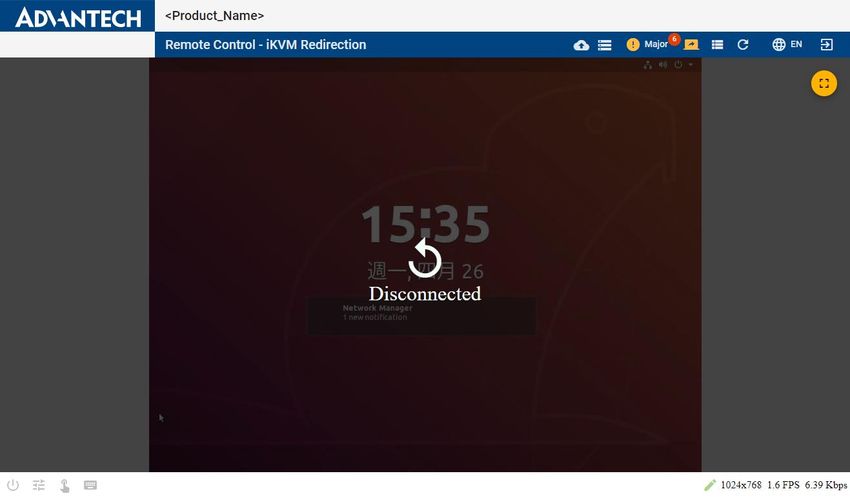
The Session Timeout tab is to set to timeout in seconds for node explorer, iKVM, and serial
console session. The default timeout of node explorer is 7 days, default timeout of iKVM is 5
minutes and default timeout of serial console session is 5 minutes. This feature is available
after nodeexp-1.19.1.
Figure 34: Session Timeout Tab
After saving the settings successfully, the following message will pop out and remind you of
the new timeout, which will be applied from the next session onwards.
Figure 35: Session Timeout Success
Copyright 2021. All rights reserved. Advantech Co. Ltd. Page 383.4.3.10 The Firewall Tab
The Firewall tab is to set port/IPv4/IPv6 firewall rule on different LAN Channel. The feature
is available after nodeexp-1.20.1.
By clicking “Add Rule” button, you can set rule of port firewall with protocol (TCP or UDP),
TCP/IP version (IPv4, IPv6, or both), port number from 1- 65535, rule (block or allow) and its
time schedule. The time scheduling for firewall is only available after nodeexp-1.22.0.
Figure 36: Add Port Firewall
To add firewall rule per channel, you can specify the rule on a range of IP addresses.
Figure 37: Add IPv4/IPv6 Address Firewall
By clicking the icon , all of the firewall rules can be deleted.
Copyright 2021. All rights reserved. Advantech Co. Ltd. Page 393.4.3.11 The VNC Service Tab
The VNC Service tab is only available if the Native VNC feature had been enabled. The
service port and session timeout of VNC service can be configured in this tab. Users can use
the VNC client (TightVNC Viewer, see Figure 39) that we only support to remote control the
OS system.
The VNC Service is available after nodeexp-1.21.0.
Figure 38: VNC Service Tab
Figure 39: TightVNC Viewer
Copyright 2021. All rights reserved. Advantech Co. Ltd. Page 403.4.3.12 The Remote Syslog Tab
All the logs of this BMC are originally stored in flash. Node Explorer provides a way of
redirecting the logs to a remote log server and can be configured via the Remote Syslog tab.
Figure 40: Remote Syslog Tab
Copyright 2021. All rights reserved. Advantech Co. Ltd. Page 413.4.4 Maintenance
3.4.4.1 The Version Tab
The Versions tab on the Configuration-Maintenance page will show version information of
the platform management firmware and components supported in Node Explorer, including
iKVM, remote storage, and so on.
Figure 41: The Version Tab
Additional information on the version of other SW components will be shown in a pop-out
dialog when you click More…
Figure 42: More Version Information on Other FW/SW
Version details can be downloaded as a file in JSON format.
3.4.4.2 The Configuration Tab
You can roll back to the default configuration in the Configurations tab. To save time
configuring different products, you can also download the current configuration file from the
Copyright 2021. All rights reserved. Advantech Co. Ltd. Page 42platform and upload the configuration file to another platform via Node Explorer. BIOS
configurations backup and rollback will be supported if BIOS feature has been enabled (only
available after nodeexp-1.22.0.)
Figure 43: The Configuration Tab
Note: Security key related steps in the tab are only available from nodeexp-1.18.0 onwards.
This feature is not available in earlier versions.
3.4.4.2.1 Load Default Configuration
All configuration settings will be restored to the factory defaults.
Figure 44: Enter Your Password for Confirmation
Copyright 2021. All rights reserved. Advantech Co. Ltd. Page 43Figure 45: Re-confirm Loading the Default Settings
Figure 46: Default Settings Successfully Loaded
Copyright 2021. All rights reserved. Advantech Co. Ltd. Page 443.4.4.2.2 Download Configuration
A message will pop-up as shown below when downloading configuration files successfully.
Figure 47: Encryption Key Popup
After clicking the Download and OK button, you can get two files:
Nodeexp_config_MM_DD_YYYY.key
Nodeexp_config_MM_DD_YYYY.config
Note: There will be only one configurations file in nodeexp-1.17.x. The .key file is available
after nodeexp-1.18.0 and later versions. If you don't get the .key file via nodeexp-1.18.0 and
later versions, please check if it's blocked by your web Brower as shown in Figure 48: Check
the Always Allow Button to Download Multiple File. Click to download the files.
Figure 48: Check the Always Allow Button to Download Multiple File
Copyright 2021. All rights reserved. Advantech Co. Ltd. Page 453.4.4.2.3 Upload Configuration
Upload the configuration file by following these steps.
Figure 49: Enter Login Password for Confirmation
Click the upload icon to upload the configuration file.
Figure 50: Select File then Press Next to Upload Configuration File
Copyright 2021. All rights reserved. Advantech Co. Ltd. Page 46Figure 51: Uploading the Configuration File
Upload the key file or enter the key in the text field. If the decryption has failed, it will
show "Decryption failed with current key." Please double check if you have used the correct
key downloaded with the paired configuration file. If the decryption is successful, it will go to
the confirmation screen as in Figure 54: Confirmation of the Applied Update.
Figure 52: Enter the Encryption Key
Copyright 2021. All rights reserved. Advantech Co. Ltd. Page 47If the configuration file is mismatched or invalid, it will show the message, "The upload file is
not a valid configuration file." Please double check if you have used the correct configuration
file downloaded from the Advantech website. If the confirmation check is successful, all
components that the settings will be applied to will be listed.
Figure 53: Confirmation Failed
Click Next to apply the confirmation of the selected components.
Note: applying confirmation to some components could break the connection.
Figure 54: Confirmation of the Applied Update
Copyright 2021. All rights reserved. Advantech Co. Ltd. Page 48Figure 55: Applying the Configuration
Once the configuration has been applied successfully, the Advantech web interface will also
download nodeexp_apply_config_report_YYYY-MM-DD.txt.
Figure 56: Configuration Successfully Applied
Copyright 2021. All rights reserved. Advantech Co. Ltd. Page 493.4.4.3 The Firmware Upgrade Tab
Firmware (NVRAM, CPLD/FPGA image, BIOS and BMC images) can be specified and
upgraded/downgraded through Advantech Node Explorer. First, the firmware image needs
to be uploaded to the BMC by clicking the Upload icon to select the image, and pressing
Upload.
Figure 57: Firmware Upgrade Tab
Figure 58: Firmware Image Uploading to the BMC
Copyright 2021. All rights reserved. Advantech Co. Ltd. Page 50A dialog box to force the upgrade will appear if you press Upgrade when the selected
firmware version is the same as the current version, as shown in Figure 59.
Figure 59: Confirmation of Upgrade
As shown in Figure 60, a dialog box to force the upgrade will appear if you press Upgrade
when the device ID of the selected firmware does not match the current firmware (i.e., you
upgrade the firmware of Product B by using the firmware of Product A).
Figure 60: Error Message during Upgrade
While the firmware is upgrading, a dialog box will appear as shown in Figure 61. All other
operations by different users or from different tabs will not be accessible during this time.
Copyright 2021. All rights reserved. Advantech Co. Ltd. Page 51Figure 61: Firmware Upgrade in Progress
Figure 62: Firmware Upgrade Successful
While the firmware is being activated, the web connection will be lost and you will need to
log in again. The web page will be refreshed automatically after activation; alternatively, you
can press F5 to refresh the page.
Copyright 2021. All rights reserved. Advantech Co. Ltd. Page 523.4.4.4 The BMC Debug Log Tab
In the BMC Debug Log tab, user review or download the single debug log by clicking the
specific file. Click the Download All button for archived BMC log files, including
“debug.archive” as bmc_log_MM_DD_YYYY.tar.gz for debugging purposes.
For flexible usage, BMC debug log is supported to output to a Syslog log file so that it can be
redirected to the remote log server (see 3.4.3.12). (Output to Syslog is available after
nodeexp-1.21.0.)
Figure 63: BMC Debug Log
Figure 64: Check debug.archive
Copyright 2021. All rights reserved. Advantech Co. Ltd. Page 533.4.4.5 The Host Screenshot Tab
The Host Screenshot tab provides functionality for troubleshooting your OS. BMC will auto-
capture the x86 host screenshot when detects x86 critical errors, like CPU IERR or CPU
MCERR, and some scenarios that are driven by BIOS, like PCI Express AER, boot errors etc.
Screenshots can be easily reviewed, downloaded, and removed via this tab.
Figure 65: The Host Screenshot Tab
Figure 66: Reviewed Screenshot by One Click
Copyright 2021. All rights reserved. Advantech Co. Ltd. Page 543.4.5 BMC Interface control
Users can enable/disable BMC functions (e.g. IPMI Over LAN, Serial Over LAN) in the BMC
Interface Control tab.
Figure 67: BMC Interface Control
Copyright 2021. All rights reserved. Advantech Co. Ltd. Page 553.5 Remote Control Session
3.5.1 System Power Control
The x86 payload host status, including the host power state, BIOS POST code, and current
BIOS boot device are displayed on the System Power Control page.
Figure 68: Server Power Control Page
BIOS POST code are data values used to indicate progress during the boot up phase. Beep
codes and checkpoints for debugging can be found here:
https://ami.com/ami_downloads/Aptio_4.x_Status_Codes_(beep_checkpoint).pdf
By clicking the menu button , you can get, download or refresh the BIOS POST code.
history.
Figure 69: BIOS POST Code History dialog
For BIOS Boot Options see the definition of Boot Option Parameters (chapter 28.12 Set
System Boot Options Commands and table 28-14) in IPMI specification v2.0 available from:
https://www.intel.com/content/www/us/en/servers/ipmi/ipmi-second-gen-interface-spec-
v2-rev1-1.html
Copyright 2021. All rights reserved. Advantech Co. Ltd. Page 56You can select different BIOS boot devices, which are used to set parameters that direct the
system boot following a system power up or reset. The boot flags only apply for one system
restart. It is the responsibility of the system BIOS to read these settings from the BMC and
then clear the boot flags. Press the Save button and the BIOS will save your boot options and
boot from the selected device during the next boot.
Figure 70: BIOS Boot Options are Saved
Please note some boot options are not supported with standard BIOS. If you need further
features support, please send a customization request to your Advantech representative.
BIOIS Boot Options Support with Advantech standard BIOS
No Override Supported
Force PXE Supported
Remote Hard Drive NA. Needs customized BIOS
Default Hard-drive Supported (incl. USB-HDD)
Default Hard-drive, Safe Mode Supported (incl. USB-HDD)
Default Diagnostic Partition N.A.
Default CD/DVD Supported (incl. USB-CD/DVD)
Remote CD/DVD N.A. Needs customized BIOS
Primary Removable Media N.A. Needs customized BIOS
Remote Primary Removable Media N.A. Needs customized BIOS
Primary Remote Media N.A. Need customized BIOS
Copyright 2021. All rights reserved. Advantech Co. Ltd. Page 57You can also read