User and installation manual - farbwerk nano
←
→
Page content transcription
If your browser does not render page correctly, please read the page content below
aquacomputer                                                FARBWERK NANO

       User and installation manual

                           farbwerk nano

                             aquasuite version X.17            ENGLISH: PAGE 1
                                                               DEUTSCH: SEITE 23
                            Current as of April 2020

All information contained in this manual is subject to change without prior notice.
                                 All rights reserved.

© 2019-2020               Aqua Computer GmbH & Co. KG                          -1-
                         Gelliehäuser Str. 1, 37130 Gleichen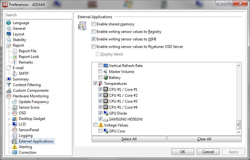
FARBWERK NANO                                                             aquacomputer
Table of contents
1. Preface.........................................................................................3
2. Safety precautions.........................................................................4
3. Scope of delivery..........................................................................4
4. Electrical connections....................................................................4
        4.1. Connector “USB” (five contacts).....................................................4
        4.2. Connector “RGBpx” (four contacts).................................................5
5. Intelligent push button...................................................................5
        5.1. Toggle strip on/off by pressing the button briefly...............................5
        5.2. Adjust strip brightness by holding the button.....................................5
        5.3. Switch profile by pressing the button twice.......................................5
6. aquasuite software........................................................................5
        6.1. Installation of the aquasuite software...............................................6
        6.2. Basic operation............................................................................6
        6.3. Symbols in the headlines................................................................6
7. Overview pages (aquasuite)...........................................................7
        7.1. Desktop mode..............................................................................7
        7.2. Creating new overview pages and activating edit mode....................7
        7.3. Adding new elements....................................................................7
        7.4. Editing existing elements................................................................8
        7.5. Values and names........................................................................8
        7.6. Detailed data elements..................................................................8
        7.7. Log data chart..............................................................................8
        7.8. User defined: Images, text, drawing elements...................................8
        7.9. Export and import of overview pages...............................................9
8. Data quick view and data log (aquasuite).......................................9
        8.1. Log settings................................................................................10
        8.2. Analyze data..............................................................................10
        8.3. Manual data export.....................................................................11
        8.4. Automatic data export.................................................................11
9. Sensor configuration...................................................................12
        9.1. Software sensors.........................................................................12
10. RGBpx configuration.................................................................13
        10.1. Create and configure additional LED controllers...........................13
        10.2. Modify existing LED controllers...................................................13
        10.3. Modify LED assignments............................................................14
        10.4. Duplicate LED controllers...........................................................14
        10.5. Multi-assign LED controllers.......................................................14
        10.6. Delete LED controllers...............................................................14
        10.7. Transparency............................................................................14
        10.8. Sound controlled effects.............................................................15
-2-                              Aqua Computer GmbH & Co. KG                              © 2019-2020
                                Gelliehäuser Str. 1, 37130 Gleichen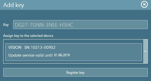
aquacomputer FARBWERK NANO
10.9. AMBIENTpx effect.....................................................................15
11. Profile management farbwerk nano............................................15
11.1. Manual profile selection............................................................15
11.2. Automatic profile selection.........................................................15
12. System settings farbwerk nano....................................................16
12.1. Device information....................................................................16
12.2. Factory defaults........................................................................16
12.3. Basic RGBpx settings.................................................................16
12.4. USB power supply.....................................................................16
12.5. Firmware update.......................................................................17
13. Playground (aquasuite)..............................................................17
13.1. Virtual Software Sensors.............................................................17
13.2. Global profiles.........................................................................17
13.3. Hotkeys...................................................................................18
14. aquasuite web..........................................................................18
14.1. Data export..............................................................................18
14.2. Data access.............................................................................19
14.3. Data import..............................................................................19
15. Basic settings (aquasuite)...........................................................19
15.1. Language................................................................................19
15.2. Reorder menu items..................................................................20
15.3. Units.......................................................................................20
15.4. Application start-up...................................................................20
15.5. Service administration...............................................................20
15.6. Audio and video.......................................................................20
15.7. Updates and update service.......................................................20
16. Technical details and care instructions........................................21
16.1. Technical details.......................................................................21
16.2. Care instructions.......................................................................21
16.3. Waste disposal.........................................................................22
16.4. Contact Aqua Computer............................................................22
1. Preface
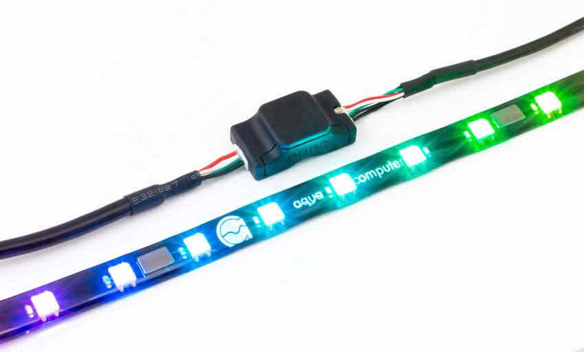
The farbwerk nano is a RGBpx effect controller for up to 90 individually address-
able LEDs.
Additionally, the device is equipped an ambient brightness sensor.
Considering the fast technical development, we reserve the right to perform alter-
ations to the products at any time. It therefore is possible that your product does
not correspond precisely to the descriptions or especially the illustrations in this
manual.
© 2019-2020 Aqua Computer GmbH & Co. KG -3-
Gelliehäuser Str. 1, 37130 Gleichen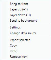
FARBWERK NANO                                                  aquacomputer
2. Safety precautions
The following safety precautions have to be observed at all times:
   ●  Read this manual thoroughly and entirely!
   ●  Save your data onto suitable media before working on your hardware!
   ●  This product is not designed for use in life support appliances, devices, or
      systems where malfunction of this product can reasonably be expected to re-
      sult in personal injury. Aqua Computer GmbH & Co. KG customers using or
      selling this product for use in such application do so at their own risk and
      agree to fully indemnify Aqua Computer GmbH & Co. KG for any damages
      resulting from such application!

3. Scope of delivery
   ●   One farbwerk nano controller
   ●   One RGBpx LED strips 32 cm, width 10 mm, 15 addressable LEDs (replace-
       ment part no. 53268)
   ●   One RGBpx cables, length 50 cm (replacement part no. 53261)
   ●   Internal version (product code 53280): One USB cable with female header
       (replacement part no. 53215)
   ●   External version (product code 53281): One USB cable with type A connec-
       tor (replacement part no. 53261)
   ●   Four black cable clips
   ●   Quick start manual

4. Electrical connections
4.1. Connector “USB” (five contacts)
This connector is used for USB communication with a PC. Connect to an USB
header of your motherboard or to a suitable USB charger. Take special care to
make sure the pin alignment matches your motherboard!
The corresponding connector on the motherboard is usually
a 9 pin connector with two independent USB ports. Both
rows of 4/5 pins can be used to connect an USB device.
The black wires (GND) are to be connected to the side of
the missing pin, see picture with colored pin assignment.
Pin assignment: Pin 1 +5 V (red)
                   Pin 2 D-     (white)
                   Pin 3 D+ (green)
                   Pin 4 GND (black)
                   Pin 5 not connected

-4-                       Aqua Computer GmbH & Co. KG                © 2019-2020
                         Gelliehäuser Str. 1, 37130 Gleichen
aquacomputer FARBWERK NANO
4.2. Connector “RGBpx” (four contacts)
Connector for up to 90 addressable LEDs.
If the RGBpx product to be connected has more than one RGBpx connector, the
connector marked with the word “IN” must be used! Additional RGBpx products
may be connected to the “OUT” connector.
Compatible RGBpx products:
● RGBpx LED-Strip (53268, 53269, 53270)
● RGBpx lighting set for PC cases (53271)
● RGBpx lighting set for monitors (53272)
● RGBpx Splitty4 (53267)
● RGBpx LED ring of ULTITUBE series reservoirs (34094, 34095, 34096,
34100, 34109, 34110)
● RGBpx LED ring for ULTITUBE (34115)
● RGBpx LED ring for aqualis 450/880 (53274)
● RGBpx LED ring for aqualis 100/150 (53276)
● RGBpx LED ring for 60 mm reservoir (53277)
● RGBpx cable (53259, 53260, 53261, 53266)
5. Intelligent push button
The push button of the farbwerk nano has three modes of operation.
5.1. Toggle strip on/off by pressing the button briefly
By briefly pressing the button, the connected strip can be switched on or off.
5.2. Adjust strip brightness by holding the button
By pressing and holding the the button, the brightness of the connected strip can
be adjusted.
5.3. Switch profile by pressing the button twice
By briefly pressing the button twice, the next profile can be activated in the order
1-2-3-4. After profile 4, profile 1 is activated again. Further information regarding
profiles can be found in chapter 11. of this manual.
6. aquasuite software
The Windows software aquasuite is an extensive software suite and can be used
for configuration and monitoring. The software is not required for operation
though. All configuration parameters can be saved into the device's memory.
Please note: Depending on the type of product you are using, some features may
not be available for your device.
© 2019-2020 Aqua Computer GmbH & Co. KG -5-
Gelliehäuser Str. 1, 37130 GleichenFARBWERK NANO aquacomputer
6.1. Installation of the aquasuite software
For configuration and monitoring of our products with USB interface, the aqua-
suite software is available for download from our website www.aqua-computer.de.
You will find the setup program in the support section of the website under Down-
loads/Software.
The setup program checks all connected USB devices for embedded update ser-
vice periods and offers various aquasuite versions depending on detected devices.
If no device with update service for the latest aquasuite version is found, a warning
is displayed and older aquasuite versions that do not require an update service
purchase can be selected for installation. For installation and update service vali-
dation, an internet connection is required.
The latest aquasuite version may also be installed if no suitable update service pe-
riod has been found in a device. Subsequently, update service may be purchased
or an existing key may be entered within the aquasuite. These functions can be ac-
cessed in the aquasuite/Updates tab.
6.2. Basic operation
The program window is divided into two main areas. On the left side, a list of
“overview pages”, data quick view, data logger, device pages, aquasuite web and
aquasuite configuration is displayed, the right side shows the details of the current-
ly selected list element. The list can be hidden or restored by clicking the arrow
symbol in the upper left corner.
List elements may be minimized or maximized for easier access by clicking the title
bar. The title bars may contain various symbols that will be explained in the follow-
ing chapter.
6.3. Symbols in the headlines
Click the plus symbol in the “Overview pages” headline to create a new
overview page.
Clicking the monitor symbol will toggle desktop mode for this overview
page. While desktop mode is active, the color of the symbol will change
to orange.
Overview page: Clicking the padlock symbol will unlock or lock this over-
view page for editing. Device: Device can not be used due to update ser-
vice problems, see “Updates and update service” for details.
Clicking the gear symbol will access the basic configuration page of the
selected list element.
In order to save all settings into a device, click the disk symbol in the
headline.
-6- Aqua Computer GmbH & Co. KG © 2019-2020
Gelliehäuser Str. 1, 37130 Gleichenaquacomputer FARBWERK NANO
This symbol indicates that communication with this device is not possible
at the moment. Check USB connection and power supply of the device if
necessary.
Clicking this symbol in the lower left corner of the aquasuite window will
display the news feed on aquasuite updates.
7. Overview pages (aquasuite)
Current sensor readings and diagrams from all supported devices can be dis-
played in overview pages. For each device a pre-configured overview page is au-
tomatically generated the first time the device is connected to the PC. These pages
can be individually modified and new pages can be created. Within one overview
page, data from all connected devices can be accessed.
7.1. Desktop mode
Each overview page can be displayed directly on your desktop. You can enable
desktop mode for an overview page by clicking the monitor symbol in the list of
overview pages. Desktop mode can only be enabled for one overview page at a
time. With desktop mode enabled, elements of the overview page may cover pro-
gram symbols on your desktop, but mouse clicks are transmitted to underlying
desktop symbols.
If a overview page is unlocked for editing while desktop mode is active, the page
will be displayed in the aquasuite window for editing and the current desktop will
be displayed as background for your convenience.
7.2. Creating new overview pages and activating edit mode
In order to create a new overview page, click the plus symbol in the headline
“Overview pages”.
Existing overview pages can be unlocked for editing by clicking lock symbol in the
page listing.
7.3. Adding new elements
If the currently selected overview page is unlocked for editing, a plus symbol is dis-
played in the top right corner of the screen. Click the symbol to add a
new element to the page and select the desired element from the follow-
ing list. All available data is displayed in a tree diagram, click the arrow
symbols to access individual items.
Confirm your selection by clicking the check symbol in the bottom right corner.
The new element will be displayed in the upper left corner and the configuration
window is displayed. Configure the element as described in the next chapters.
© 2019-2020 Aqua Computer GmbH & Co. KG -7-
Gelliehäuser Str. 1, 37130 GleichenFARBWERK NANO aquacomputer
7.4. Editing existing elements
If the currently selected overview page is unlocked for
editing, right-clicking an element will access a context
menu.
To access the settings of an element, select “Settings”
in the context menu or simply double click the element.
If you want to move an element, “drag” this element
while holding down the mouse button. Release the
mouse button when the element is at the desired posi-
tion.
7.5. Values and names
If the currently selected overview page is unlocked for editing, right-click an ele-
ment and select “Settings”. You may also double click the element.
Font face, size and color as well as position, decimal places and unit can be con-
figured for individual values.
7.6. Detailed data elements
If the currently selected overview page is unlocked for editing, right-click an ele-
ment and select “Settings”. You may also double click the element. Apart from po-
sition, size and color, the style of the element can be selected and configured. The
following styles are available:
● Headline only: Compact display as a headline.
● Text: Displays the numerical value in a box with a headline.
● Bar graph: Displays numerical value as well as bar graph.
● Chart: Displays the value in chronological sequence as a chart.
● Gauge: Displays the value as a analog gauge.
All display styles offer extensive configuration options, additionally statistical data
such as minimum, maximum and average can be displayed.
7.7. Log data chart
This element can be used to display charts on overview pages. The charts have to
be created using the data log functionality of the aquasuite before they become
available for overview pages. Please refer to the next chapter for details. Once a
chart has been configured, it can be selected from the “Chart selection” list on the
“Display” tab of the settings dialog.
7.8. User defined: Images, text, drawing elements
By using user defined controls, simple drawing elements such as circles, rectangles
and texts as well as images and more sophisticated elements can be added to an
overview page. To do so, add an “User defined” element to an overview page.
Switch to the “Display” tab in following dialog box, select the type of element to be
-8- Aqua Computer GmbH & Co. KG © 2019-2020
Gelliehäuser Str. 1, 37130 Gleichenaquacomputer FARBWERK NANO
created from the drop down menu and confirm your selection by clicking the
“Load preset” button. Depending on the type of element, an additional dialog may
appear before the code (XAML, Extensible Application Markup Language) of the
new element is displayed in the lower part of the dialog window. You may want to
customize the code. By clocking the “Ok” Button, the new control is saved to the
overview page.
Step-by-step example to add an image: Select “Image” from the drop down menu
and click the “Load preset” button. Select an image file using the following file se-
lection dialog. The code is then displayed in the lower part of the dialog window
an can be modified. Save the new control by clicking the “Ok” button. The picture
will be displayed on the overview page.
More complex controls such as data bindings and animations are also available
but will require some programming experience for configuration.
7.9. Export and import of overview pages
Elements and complete overview pages can exported from the aquasuite and can
then be imported either on the same PC or on other PCs. For export as well as im-
port, the overview page must be in edit mode.
To export a complete page, right click a free spot of the page and select “Export
page” from the context menu. To export individual elements, select the element or
elements, perform a right click and select “Export selected” from the context menu.
For import, right click a free spot of the page and select “Import page” or “Import
items”from the context menu. Using “Import page”, the current page will be delet-
ed and only the imported page items will be displayed, using “Import items” will
add the items from file to the current page without altering the existing items. Dur-
ing import, the elements will be assigned to devices using the following scheme:
If a device with identical serial number is found on the computer, no changes are
made.
If no device with identical serial number is found on the computer, the element will
be assigned to the first device found of identical type.
When importing complex pages with elements referring to more than one device, it
is recommended to edit the device assignment in the file using a text editor prior to
importing.
8. Data quick view and data log (aquasuite)
All data currently monitored by the aquasuite can be accessed in the “Data quick
view” section. This includes data from connected USB devices as well as hardware
data supplied by the Aqua Computer background service. Displayed data may be
filtered using the text box next to the magnifier icon, a chart shows the develop-
ment over a maximum of ten minutes. All data shown here is not stored perma-
nently.
© 2019-2020 Aqua Computer GmbH & Co. KG -9-
Gelliehäuser Str. 1, 37130 GleichenFARBWERK NANO aquacomputer
In contrast, the “Data log” may be used to selectively and permanently store data
from all connected Aqua Computer devices and hardware data supplied by the
background service. Logged data can then be analyzed by creating charts or be
exported to files. Data is only logged while the aquasuite software is being execut-
ed.
8.1. Log settings
The log settings can be accessed by clicking the “Log settings” element
below the “Data log” headline in the listing. To log data, create a new
log data set by clicking the plus symbol in the upper right corner of the
settings window. Enter name, time interval and configure automatic deletion of old
data to meet your requirements. You may then add the data sources to log by
clicking the plus symbol in the “Data sources” window section. You may add an
unlimited number of data sources to each log data set, the total number of log
data sets is also unlimited.
8.2. Analyze data
Logged data can be visually evaluated as charts. To do so, select “Ana-
lyze data” below the “Data log” headline in the listing. The chart will ini-
tially be empty, directly below the chart are eight buttons to modify the
chart. In the lower section of the window, the chart data can be configured.
To add data to the chart, first select the “Data sources” tab in the chart configura-
tion and select a data set to be displayed. If no data sources are available, you
will have to configure the log settings as described in the chapter “Log settings” of
this manual. Select the time period to be displayed on the right side of the window
and add the data to the chart by clicking the “Add data to chart” button. Repeat
this procedure if you want to display more than one data set in the chart.
You may modify the chart using the “Chart setup” and “Data series setup” tabs.
Finally, you can use the “Chart manager” tab to save the current chart configura-
tion and to load or delete previously saved configurations. All saved chart configu-
rations will be available on overview pages for the “Log data chart” element.
The currently displayed chart can be edited by using the buttons directly below the
chart and may also be saved as an image file. The button corresponding to the
currently selected function is highlighted by an orange frame. Please refer to the
following list for details on each function:
To save the currently displayed chart as an image file, click the floppy
disk symbol and select a name and location in the following dialog.
This function can be used to add horizontal lines to the chart. While this
function is activated, simply click into the chart to add a line at the current
cursor position.
- 10 - Aqua Computer GmbH & Co. KG © 2019-2020
Gelliehäuser Str. 1, 37130 Gleichenaquacomputer FARBWERK NANO
This function can be used to add vertical lines to the chart. While this
function is activated, simply click into the chart to add a line at the current
cursor position.
This function can be used to add annotations to the chart. While this
function is activated, simply click into the chart to add an annotation at
the current cursor position. By clicking into the text box, you may edit the
text. You may also drag the little circle beside the text box to move the connecting
line to the desired position. Use drag and drop to move existing annotations.
This function can be used to remove horizontal/vertical lines or annota-
tions from the chart. While this function is activated, simply click the ele-
ment to be removed.
This function can be used to move the visible portion of the chart. Press
and hold the mouse button while moving the cursor in the chart to select
the position to be displayed, then release the button.
This function can be used to zoom in and out. Use the mouse wheel or
select the area to be displayed. You can reset the zoom settings by dou-
ble-clicking in the chart area.
This function will completely remove the chart.
8.3. Manual data export
Saved data can be exported from the data log into a XML file. To do so, select
“Analyze data” below the “Data log” headline in the listing. Select the “Data
sources” tab in the chart configuration and select a data set to be exported. If no
data sources are available, you will have to configure the log settings as described
in the chapter “Log settings” of this manual. Select the time period to be exported
on the right side of the window and start the export process by clicking the “Export
data” button. Enter a file name and path in the following dialog window.
8.4. Automatic data export
The automatic data export feature can be used to save data from the
aquasuite into an XML file on the hard disk or in the RAM (“memory
mapped file”) in a regular time interval. The automatic data export will al-
ways overwrite the previously saved data, so the file always contains only the most
recent data set. Select “Automatic data export” below the “Data log” headline in
the listing to access the settings screen. Create a new export data set by clicking
the plus symbol in the upper right corner of the screen. Enter name, path and time
interval to meet your requirements. You may then add the data sources to log by
clicking the plus symbol in the “Data sources” window section. You may add an
unlimited number of data sources to each export data set, the total number of ex-
port data sets is also unlimited.
© 2019-2020 Aqua Computer GmbH & Co. KG - 11 -
Gelliehäuser Str. 1, 37130 GleichenFARBWERK NANO aquacomputer
9. Sensor configuration
Select “Sensors” from the device list below the “farbwerk nano” entry. In
the upper area, the 16 available sensors are displayed including current
data. In the lower area, the currently selected sensor can be configured.
9.1. Software sensors
The 16 sensors in the list are software sensors and can be used to transmit sensor
data to the farbwerk nano controller from the computer by USB connection.
During installation of the aquasuite, the background service “Aqua Computer Ser-
vice” is also installed. This service supplies various data from PC components and
imported data from aquasuite web, additionally sensor data provided by third par-
ty software can be accessed. In order to access third party software data, the third
party software has to be correctly installed, configured and running.
Currently, the “Aqua Computer Service” supports data transfer from “HWiNFO”
(REALiX, Freeware, www.hwinfo.com) and “AIDA64” (FinalWire Ltd., subject to li-
cense fees, www.aida64.com).
HWiNFO automatically exports all sensor values, the “Sensor Status” Window has
to be open.
In the AIDA64 preferences menu, writing to WMI must be activated in the „external
applications“ sub-menu:
By clicking the plus symbol labeled “Data source”, one of the provided sensors
can be assigned to the selected software sensor.
- 12 - Aqua Computer GmbH & Co. KG © 2019-2020
Gelliehäuser Str. 1, 37130 Gleichenaquacomputer FARBWERK NANO
For each software sensor, a scale factor and an offset may be configured for ma-
nipulation of the displayed sensor value. Data from third party software regularly
requires the scale factor to be adjusted.
10. RGBpx configuration
Select “RGBpx” from the device list below the “farbwerk nano” entry.
In the RGBpx overview, select the RGBpx output.
After selecting the RGBpx output, new LED controllers can be added. Po-
sition and number of assigned LEDs can be modified for existing LED controllers,
multiple assignments and controller settings can be modified. Each LED controller
can be activated or deactivated for each of the four available profiles as well.
10.1. Create and configure additional LED controllers
After selecting the RGBpx output, new LED controllers can be added by
clicking the plus symbol. Alternatively, use the right mouse button and se-
lect “New” from the context menu. Select the desired effect from the su-
perimposed list of available effects. The controller name can be altered from its
default as well. Confirm you selection by clicking the check symbol in the lower
right corner.
The configuration of the newly added LED controller can be modified in the lower
area of the window. Each LED controller can activated or deactivated for each of
the four available profiles as well. Most effects offer extensive customization op-
tions such as color selection or speed adjustment. Additionally, many effects can
be configured to modify effect parameters depending on current sensor data.
In total, up to 20 LED controllers can be configured.
10.2. Modify existing LED controllers
Existing LED controllers can be selected by clicking the corresponding col-
or bars, the configuration of the selected controller can then be modified
in the lower area of the window. Each LED controller can be activated or
deactivated for each of the four available profiles as well.
By clicking the gear symbol, the effect to be displayed can be changed and the
controller name can be altered. Confirm you selection by clicking the check sym-
bol in the lower right corner.
© 2019-2020 Aqua Computer GmbH & Co. KG - 13 -
Gelliehäuser Str. 1, 37130 GleichenFARBWERK NANO aquacomputer
10.3. Modify LED assignments
Existing LED controllers can be moved by using “drag&drop”on the corre-
sponding color bars. The horizontal position of the color bar defines the
position of the effect on the connected LEDs. The vertical position deter-
mines the priority of the LED controllers, if multiple controllers are assigned to a
range of LEDs. Controllers positioned further up in the list have higher priority than
controllers further below. (See chapter Transparency as well.)
The length of the bar (corresponding to the number of LEDs assigned) can be
changed by moving the right/left edge of the color bar.
10.4. Duplicate LED controllers
Select the LED controller(s) to be duplicated and click the duplicate sym-
bol to create new LED controllers using identical configurations. Alterna-
tively, use the right mouse button and select “Duplicate” from the context
menu.
These duplicated controllers will initially have configurations identical to the origi-
nal controllers, but can be modified without affecting the original controllers.
In total, up to 20 LED controllers can be configured.
10.5. Multi-assign LED controllers
Select the LED controller(s) to be multi-assigned and click the multi-assign
symbol to create multiple entries for the selected controllers. Alternatively,
use the right mouse button and select “Multi assign” from the context
menu.
These multi-assigned controllers share a common configuration. Apart from the
position of the assigned LED area, configuration changes will always affect all of
the multi-assigned controllers.
In total, up to 60 assignments can be configured.
10.6. Delete LED controllers
Select the LED controller(s) to be deleted and click the delete symbol to
delete the selected controllers. Alternatively, use the right mouse button
and select “Delete” from the context menu.
10.7. Transparency
The default configuration defines all colors of the LED controllers in the
farbwerk nano as “solid”, meaning without transparency. If multiple LED
controllers are assigned to a LED or an area of LEDs, the LED controller
with the highest priority determines the color of the LED. As described above, this
is always the LED controller the furthest up in the list of controllers.
However, the opacity of almost all color definitions in the LED controllers can be
individually configured, resulting in a varying level of transparency. The corre-
- 14 - Aqua Computer GmbH & Co. KG © 2019-2020
Gelliehäuser Str. 1, 37130 Gleichenaquacomputer FARBWERK NANO
sponding sliders in the color selection are identified by a drop symbol. This feature
can be used to blend and mix colors where overlapping LED controllers are con-
figured.
10.8. Sound controlled effects
Sound controlled effects can be used to visualize the current audio output of the
computer. A warning in the LED configuration area will notify you if audio analysis
has been disabled in the aquasuite. In this case, please enable the feature in the
general aquasuite configuration. The general aquasuite configuration can also be
used to modify existing audio filters and define custom audio filters.
10.9. AMBIENTpx effect
The AMBIENTpx effect replicates the border area of the current monitor content on
the configured LEDs. This effect is meant to be used with LED strips installed to the
rear of the monitor for background lighting. A warning in the LED configuration
area will notify you if video analysis has been disabled in the aquasuite. In this
case, please enable the feature in the general aquasuite configuration.
For each configured AMBIENTpx effect, please select the correct monitor, edge
and desktop range to evaluate for the effect.
Prerequisites and limitations:
● The AMBIENTpx effect requires Microsoft Windows operating system version
8.1 or newer.
● Screen content preventing analysis by DRM or similar methods cannot be
analyzed.
● Multi monitor setups must be configured using standard procedures of the
operating system. Special features of the graphics card driver like “NVIDIA
Surround” or “AMD Eyefinity” must be disabled.
● AMBIENTpx is not available while “NVIDIA G-Sync” is active.
11. Profile management farbwerk nano
Select “Profiles” from the device list below the “farbwerk nano” entry.
The profile management can be used to select up to four profiles manu-
ally or automatically. In order to use this functionality, LED controllers
must be assigned to the individual profiles as described above.
11.1. Manual profile selection
Select the profile to be activated by clicking the corresponding button.
11.2. Automatic profile selection
The active profile can automatically be selected depending on sensor readings, a
timer or depending on running applications. A variety of conditions can be config-
© 2019-2020 Aqua Computer GmbH & Co. KG - 15 -
Gelliehäuser Str. 1, 37130 GleichenFARBWERK NANO aquacomputer
ured, with (applicable) conditions further down the list having a higher priority than
entries further up.
The duration of the profile timer can be configured and is available for profile se-
lection as a “data source”. If “Reset timer automatically” is selected, the timer will
be reset after the set period of time and count up again, otherwise the timer will
stop when reaching the maximum value.
12. System settings farbwerk nano
Select “System” from the device list below the “farbwerk nano” entry.
12.1. Device information
The details displayed here might be required when you contact our service for sup-
port. You may enter a “Device description” for easier identification, this text will be
displayed in the device list and in the data quick view.
12.2. Factory defaults
Click the button “Reset device to factory defaults” in the aquasuite for a complete
reset of all settings. You will have to completely reconfigure the device after reset-
ting it to factory defaults!
12.3. Basic RGBpx settings
The RGBpx output can be completely disabled and the brightness can be reduced
using a slider.
12.4. USB power supply
The farbwerk nano is supplied with power through the USB connection. In default
configuration, power consumption is limited to a maximum current of 0.5 Amps.
This value complies with the maximum allowed current according to the USB spec-
ification. If a large number of LED is connected, the brightness is automatically re-
duced accordingly.
Alternatively, the current can be limited to a higher value of 2 Amps by activating
the check box. Do not use this function unless the connected USB port is explicitly
specified for a current of at least 2 Amps by the manufacturer! If the maximum
permissible current of the USB port is exceeded, permanent damage is possible!
Consult the manual of your motherboard/hub/charger for details or contact cus-
tomer support of the manufacturer/importer.
- 16 - Aqua Computer GmbH & Co. KG © 2019-2020
Gelliehäuser Str. 1, 37130 Gleichenaquacomputer FARBWERK NANO
12.5. Firmware update
The most up to date firmware for all supported devices is always included in the
current version of the aquasuite software. The button “ Update firmware now” will
start the update process for the device firmware.
During the firmware update process, do not disconnect the device from the PC
and do not power down the PC! After the firmware is successfully updated, the
aquasuite software will be automatically closed.
13. Playground (aquasuite)
Click the entry “Playground” to configure Virtual Software Sensors, global profile
management and hotkeys.
13.1. Virtual Software Sensors
Virtual Software Sensors can be used for extensive yet easy to use adapta-
tion and calculation of sensor values using mathematical and logical
functions as well as filters.
Create a new Virtual Software Sensor by clicking the plus symbol in the upper right
corner of the “Virtual Software Sensors” window. Each Virtual Software Sensor al-
ways has an “Out” element which will provide the resulting sensor value. In the
settings dialog of this element, the name and unit of the sensor can be configured.
You can now add data sources and function blocks to the lower area of the sensor
window and connect inputs and outputs of the blocks with lines. Connect the out-
put of the last function block with the “Out” element.
The resulting virtual sensor can be used within the aquasuite software, for example
for overview pages, additionally it may be transmitted via USB connection to con-
nected devices that feature software sensors.
The following (very simple) example calculates the average out of two tempera-
tures:
13.2. Global profiles
The global profile management can be used to conveniently change set-
tings in multiple devices simultaneously and activate desktop pages. Indi-
vidual actions can be defined for each of the four profiles, switching be-
tween profiles can either be done manually or automatically depending on config-
urable rules.
© 2019-2020 Aqua Computer GmbH & Co. KG - 17 -
Gelliehäuser Str. 1, 37130 GleichenFARBWERK NANO aquacomputer
In order to use this feature, set up profiles within the individual device configura-
tions first. These profiles can then be activated using the global profile manage-
ment. Not every type of device supports profiles.
Buttons in the upper window area can be used to switch between global profiles.
Alternatively, the profile icon in the title bar of the aquasuite window or a profile
icon in the system tray may be used.
Example use cases: Switching of LED illumination settings depending on current
time of day or modification of fan settings when a graphics application is
launched.
Notice for profile activation depending on running applications: During configura-
tion of the respective rule in the aquasuite, the application to be configured must
already be running. The application selection within the aquasuite will always show
currently running applications and processes only.
13.3. Hotkeys
Hotkeys are key combinations that will be processed system-wide and can
activate global profiles or desktop pages. The configured key combina-
tions will be registered in the operating system and be processed by the
background service. If the configured actions only use the profile management,
the aquasuite does not have to be running for hotkeys to be operational; if desk-
top pages are used, the aquasuite must be running.
Do not use key combinations for this function that are required by other applica-
tions.
14. aquasuite web
Click the entry “aquasuite web” to publish data on the internet or import data from
the internet. The server for this service is operated by Aqua Computer and provid-
ed for use with the aquasuite, without warranty for error free operation or perma-
nent availability. Aqua Computer reserves the right to limit or cancel this service at
any time.
14.1. Data export
To publish data, create a new export data set by clicking the plus symbol
in the upper right corner of the “Data export” window. The name of the
data set may be modified to meet your requirements. You may then add
the data sources to export by clicking the plus symbol in the “Data sources” win-
dow section. By clicking the gear symbol, the name of the corresponding value
can be changed. Up to 30 data sources can be added to each export data set, the
total number of export data sets is limited to 10. All selected values will be trans-
mitted to the Aqua Computer server by the Aqua Computer background service
approximately every 15 seconds, even after closing the aquasuite.
- 18 - Aqua Computer GmbH & Co. KG © 2019-2020
Gelliehäuser Str. 1, 37130 Gleichenaquacomputer FARBWERK NANO
Notice regarding data security: All data contained in the configured export data
sets is transmitted to the Aqua Computer server with transport security. The server
stores the data set in volatile memory until a new data set is received or until 10
minutes have passed. Data received is not permanently stored, data is also not
correlated to IP addresses or other personal data. Data on the server may be ac-
cessed by anyone without restrictions, furthermore automatic data collection and
recording through third parties is possible. Use the data export feature for data
that you want to publish publicly and are allowed to do so only.
14.2. Data access
Published data can be obtained from the Aqua Computer server in vari-
ous formats. Generally, the “access key” is required to access data.
In addition to access through any internet browser and importing data into the
aquasuite, data is also available in JSON format and compatible to Circonus.
Furthermore, the server generates banner images in two different sizes from the
transmitted data, suitable to be included in forums signatures. The code required
for the Aqua Computer forums is provided for your convenience.
14.3. Data import
To import a data set from the Aqua Computer server, the “access key” of
the data set is required. The access key can be found in the aquasuite on
the computer providing the data in the “Data access” section.
Create a new import entry by clicking the plus symbol in the upper right corner of
the “Data import” window. Enter the access key of the data set to be imported. Up
to 10 data sets (each containing up to 30 values) can be configured.
In order to verify that data is being imported, use the “Data quick view” feature in
the aquasuite. Navigate to “Data from Aqua Computer service”, then “aquasuite
web”. For each imported data set, you should find an entry with the name of the
data set containing the individual values. It may take a few seconds before import-
ed data is displayed.
15. Basic settings (aquasuite)
Click the entry “Settings” below the headline “aquasuite” to access basic
settings for language, units and start-up of the software.
15.1. Language
Select a language from the drop down menu. After changing the language setting,
the software will have to be restarted.
© 2019-2020 Aqua Computer GmbH & Co. KG - 19 -
Gelliehäuser Str. 1, 37130 GleichenFARBWERK NANO aquacomputer
15.2. Reorder menu items
The order in which overview pages and devices are displayed in the list can be ad-
justed to you preference. Activate the reorder mode by clicking the “Edit menu or-
der” button or by clicking and holding one of the elements for a few seconds. Sort
the list items by clicking the arrow symbols and exit the reorder mode by clicking
the check symbol on the right side of the window when done.
15.3. Units
Select the units to be used for temperature and flow values from the drop down
menus. After changing these settings, the software will have to be restarted.
15.4. Application start-up
You may customize start-up behavior to suit your preferences. You may also select
to hide the task bar symbol of the software when minimized.
15.5. Service administration
The background service configures special USB settings for all connected
Aqua Computer devices, provides hardware data, software sensors, pro-
file management and aquasuite web and should therefore always be ac-
tive.
The hardware monitoring features of the background service can be disabled for
specific categories if errors occur.
15.6. Audio and video
The background service can analyze audio and video data and provide it
to connected devices. Both functions can be enabled and disabled sepa-
rately.
Notices for video analysis: Screen content preventing analysis by DRM or similar
methods cannot be analyzed. If a graphics card is configured for variable refresh
rate or a modified refresh rate, video analysis may fail; please deactivate this func-
tion in the graphics settings of the operating system if necessary.
15.7. Updates and update service
For software activation, all aquasuite versions starting with version 2017
require an active update service for the initial release date of the respec-
tive version. Update service periods are generally assigned to individual
devices, brand-new devices automatically contain update service for a specific pe-
riod depending on the type of the device. For software activation, at least one de-
vice in the computer must contain a corresponding update service period that in-
cludes the release date of this software version. If a valid update service period is
detected for at least one device, all devices connected to the computer can be
- 20 - Aqua Computer GmbH & Co. KG © 2019-2020
Gelliehäuser Str. 1, 37130 Gleichenaquacomputer FARBWERK NANO
used with this version. It is not mandatory that each device has a corresponding
update service period. For update service validation, the aquasuite requires an in-
ternet connection.
After successful validation, a file containing current data is stored on the computer.
A re-validation is performed only if a new software version (update) is installed or
upon connection of new devices. New devices can not be used prior to re-valida-
tion, even if other devices with corresponding update service periods are connect-
ed at the same time.
To purchase update service, please use the “Buy” button, which will open a web-
site with current prices and payment options.
If you have received a
key for update service
with a device or
bought one separately,
you may enter the key
after clicking the “Reg-
ister” button. Select a
currently connected
USB device from the
list for update service
assignment. After click-
ing the “Register key” button, the update service period is permanently assigned to
the selected device and stored on the Aqua Computer update server. The key will
not have to be re-entered after re-installation of the software or transfer of the de-
vice to another computer, but transferring the update service period to another de-
vice is not possible.
During update service validation and software activation, device serial numbers
and a calculated computer ID are transmitted to and stored on the update server.
No further personal information such as IP addresses are stored.
16. Technical details and care instructions
16.1. Technical details
Power supply: 5 V DC ±5 %, max. 0.5/2 A (configurable)
Dimensions: 29 x 16 x 10 mm
Ambient temperature range: 10 to 40 °C (noncondensing)
16.2. Care instructions
Use a dry and soft cloth for cleaning. All electronic components and headers must
not get in contact with coolant or water!
© 2019-2020 Aqua Computer GmbH & Co. KG - 21 -
Gelliehäuser Str. 1, 37130 GleichenFARBWERK NANO aquacomputer
16.3. Waste disposal
This device has to be disposed of as electronic waste. Please check
your local regulations for disposal of electronic waste.
16.4. Contact Aqua Computer
We are always happy to answer questions regarding our products and to receive
feedback. For answers on frequently asked questions, please also check our web-
site www.aqua-computer.de. You might also want to visit our forums and discuss
our products with experienced moderators and thousands of members – available
24/7. To get in direct contact with our customer support team, we offer several
options:
Email: support@aqua-computer.de
Postal address: Aqua Computer GmbH & Co. KG
Gelliehäuser Str. 1
37130 Gleichen
Germany
Tel: +49 (0) 5508 9749290 (9-16 h CET, German and English language)
- 22 - Aqua Computer GmbH & Co. KG © 2019-2020
Gelliehäuser Str. 1, 37130 GleichenYou can also read