LED illuminated pushbutton for panel mounting - future use! - R. STAHL

Page created by Lewis Burgess
 
CONTINUE READING
LED illuminated pushbutton for panel mounting - future use! - R. STAHL
North American                   DE
                                                             operating instructions                US
                                                                Additional languages r-stahl.com
                                                                                                   FR
                                                                                                   IT
                                                                                                   ES
                                                                                                   RU
                                                                                                   NL
                                                                                                   DK
                                                                                                   SE
                                                                                                   FI
                                                                                                   PT
                                                                                                   GR
                                                                                                   PL
                                                                                                   CZ
                                                                                                   SK
                                                                                                   HU
                                                                                                   SL
                                                                                                   RO
                                                                                                   BG
LED illuminated pushbutton                                                                         LV
for panel mounting                                                                                 LT
                                                                                                   EE
                                                                                                   CH
Series 8018/3
                                                                                                   KR
                                                                                                   CN

                                                         –
                                         r future use!
                             –   Save fo
LED illuminated pushbutton for panel mounting - future use! - R. STAHL
Table of Contents
DE
US
           Table of Contents
           1      General Information .............................................................................................3
FR         1.1    Manufacturer........................................................................................................3
IT         1.2    About these Operating Instructions......................................................................3
ES         1.3    Further Documents ..............................................................................................3
           1.4    Conformity with Standards and Regulations........................................................3
RU
           2      Explanation of Symbols .......................................................................................4
NL         2.1    Symbols used in these Operating Instructions.....................................................4
DK         2.2    Symbols on the Device ........................................................................................4
SE         3      Safety...................................................................................................................5
           3.1    Intended Use........................................................................................................5
FI
           3.2    Personnel Qualification ........................................................................................5
PT         3.3    Residual Risks .....................................................................................................6
GR         4      Transport and Storage .........................................................................................7
           5      Mounting and Installation .....................................................................................8
PL
           5.1    Installation of Devices 8018/3 ..............................................................................8
CZ         5.2    Installation of Devices into the Panel ...................................................................8
SK         5.3    Changing the Color of the Actuator Caps ............................................................9
HU         6      Commissioning ....................................................................................................9
           7      Maintenance, Overhaul, Repair ...........................................................................9
SL
           7.1    Maintenance ........................................................................................................9
RO         7.2    Overhaul ..............................................................................................................9
BG         7.3    Repair ..................................................................................................................9
           8      Returning the Device .........................................................................................10
           9      Cleaning.............................................................................................................10
LT         10     Disposal .............................................................................................................10
EE         11     Accessories and Spare Parts.............................................................................11
CH         12     Appendix A.........................................................................................................11
           12.1   Technical Data ...................................................................................................11
KR
           13     Appendix B.........................................................................................................14
CN         13.1   Dimensions/Fastening Dimensions....................................................................14

     2       LED illuminated pushbutton
             for panel mounting
             Series 8018/3
General Information
                                                                                                           DE
1       General Information                                                                                US
1.1     Manufacturer                                                                                       FR
        R. STAHL Schaltgeräte GmbH                 R. STAHL, INC.                                          IT
        Am Bahnhof 30                              13259 N. Promenade Blvd.                                ES
        74638 Waldenburg                           Stafford, TX 77477
                                                                                                           RU
        Germany                                    USA
        Tel.:     +49 7942 943-0                   Tel.:          +1 800 782-4357                          NL
        Fax:      +49 7942 943-4333                Fax:           +1 281 313-9302                          DK
        Internet: r-stahl.com                      Internet:      r-stahl.com                              SE
        E-Mail:   info@r-stahl.com                 E-Mail:        sales.us@r-stahl.com
                                                                                                           FI
        R. STAHL Ltd.
        #303, 8925-51 Avenue                                                                               PT
        Edmonton, AB T6E 5J3                                                                               GR
        Canada                                                                                             PL
        Tel.:     +1 877 416 4302
                                                                                                           CZ
        Fax:      +1 780 469 5525
        Internet: r-stahl.com                                                                              SK
        E-Mail:   info.ca@r-stahl.com                                                                      HU
                                                                                                           SL
1.2     About these Operating Instructions
        ▶   Read these operating instructions, especially the safety notes, carefully before use.          RO
        ▶   Observe all other applicable documents (see also chapter 1.3).                                 BG
        ▶   Keep the operating instructions throughout the service life of the device.
                                                                                                           LV
        ▶   Make the operating instructions accessible to operating and maintenance staff at all times.
        ▶   Pass the operating instructions on to each subsequent owner or user of the device.             LT
        ▶   Update the operating instructions every time R. STAHL issues an amendment.                     EE
                                                                                                           CH
        ID No.:                                                290432 / 8018607300
                                                                                                           KR
        Publication code:                                      2021-06-11·IO00·III·en·00
                                                                                                           CN
        The original instructions are the American edition.
        They are legally binding in all legal affairs.

1.3     Further Documents
        • Data sheet
        For documents in other languages, see r-stahl.com.

1.4     Conformity with Standards and Regulations
        Certificates for USA and Canada: r-stahl.com.

 290432 / 8018607300                                          LED illuminated pushbutton              3
 2021-06-11·IO00·III·en·00                                    for panel mounting
                                                              Series 8018/3
Explanation of Symbols
DE
US
     2     Explanation of Symbols
FR   2.1   Symbols used in these Operating Instructions
IT         Symbol                         Meaning
ES                                        Handy hint for making work easier
RU
                                          Dangerous situation which can result in fatal or severe injuries
NL               DANGER!                  causing permanent damage if the safety measures are not
DK                                        complied with.
SE                                        Dangerous situation which can result in severe injuries if the
                 WARNING!                 safety measures are not complied with.
FI
                                          Dangerous situation which can result in minor injuries if the
PT               CAUTION!                 safety measures are not complied with.
GR
           NOTE!                          Dangerous situation which can result in material damage if the
PL                                        safety measures are not complied with.
CZ
     2.2   Symbols on the Device
SK
           Symbol                         Meaning
HU
                                          UL test mark, proven conformity of the product with the safety
SL                                        regulations of the USA and Canada
RO
                                          Input
BG
                      15649E00

LV
                                          Output
LT
                      15648E00

EE
CH
KR
CN

     4       LED illuminated pushbutton                                                290432 / 8018607300
             for panel mounting                                                     2021-06-11·IO00·III·en·00
             Series 8018/3
Safety
                                                                                                          DE
3       Safety                                                                                            US
        This device has been manufactured according to the state of the art of technology.
        Recognized safety-related rules and standards were observed in this process.                      FR
        The device must nevertheless be operated properly and carefully at all times.                     IT
        Incorrect operation can put the user and other persons in danger. Damage to the device,
                                                                                                          ES
        environment and material assets is also possible.
                                                                                                          RU
        ▶ Use the device only                                                                             NL
           - if it is not damaged
                                                                                                          DK
           - for the purpose for which it is defined
               (see Section "Intended use")                                                               SE
           - in accordance with these operating instructions.                                             FI
            The nature of these instructions is only informative and does not cover all of the details,   PT
            variations or combinations in which this equipment may be used, its storage, delivery,
            installation, safe operation and maintenance                                                  GR
            Since conditions of use of the product are outside of the care, custody and control of        PL
            the manufacturer, the purchaser should determine the suitability of the product for his
                                                                                                          CZ
            intended use, and assumes all risk and liability whatsoever in connection therewith
                                                                                                          SK
3.1     Intended Use                                                                                      HU
        The illuminated pushbutton type 8018/3 switches load, control and signal circuits,
                                                                                                          SL
        and indicates command states by means of a light signal by lighting up or going out.
        It is suited for installation on enclosure walls, electric device covers, panels or control       RO
        cabinets.                                                                                         BG
        It consists of a main assembly with 2 contact elements in flameproof enclosure, an indicator
        lamp element equipped with an LED as its light source as well as a front part for control.        LV
        The illuminated pushbutton is certified for use in hazardous areas of Class I, Div. 2 and         LT
        Class I, Zone 1.                                                                                  EE
3.2     Personnel Qualification                                                                           CH
        All activities on the device may only be performed by a qualified specialist.                     KR
        This primarily applies to work in the following areas:
                                                                                                          CN
        • Product selection, project engineering and modification
        • Mounting/dismounting the device
        • Installation
        • Commissioning
        • Maintenance, repair, cleaning

        The specialist who performs these activities must be familiar with the relevant national
        standards and regulations for electrical engineering.

        Additional knowledge is required for any activity in hazardous areas! R. STAHL recommends
        having a level of knowledge equal to that described in relevant standards.

 290432 / 8018607300                                         LED illuminated pushbutton              5
 2021-06-11·IO00·III·en·00                                   for panel mounting
                                                             Series 8018/3
Safety
DE
     3.3      Residual Risks
US
FR   3.3.1 Explosion Hazard
IT         Explosion hazards cannot be entirely eliminated in hazardous areas.

ES            ▶ Perform all activities in hazardous areas with the utmost care at all times!
RU
              Possible hazards ("residual risks") can be categorized according to their cause:
NL
DK            Damage to the device
SE            The device may be warped, dented or scratched during transport, mounting or
              commissioning. This can cause it to no longer be sealed. A damaged seal can render the
FI
              device's explosion protection partially or completely ineffective.
PT            This may result in explosions causing serious or fatal injuries to persons.
GR            To prevent this, comply with the following safety measures:
              ▶ Transport the device only in its original packaging or in equivalent packaging.
PL            ▶ Check the packaging and the device for damage. Report any damage to R. STAHL
CZ              immediately.
SK            ▶ Store the device in its original packaging in a dry place (with no condensation),
                and make sure that it is stable and protected against the effects of vibrations and knocks.
HU
SL            Too much heating or electrostatic charge
              A subsequent conversion or painting can change the state of the device in such a way
RO
              that it is no longer explosion-protected. Improper cleaning can also cause the device to heat
BG            up severely or become electrostatically charged. This can cause sparks. This may result in
LV            explosions causing serious or fatal injuries to persons. To prevent this, comply with the
              following safety measures:
LT
              ▶ Commission the device within the prescribed operating conditions only
EE                (see the label on the device and the "Technical data" chapter).
CH
              Damaged seal (impairment of IP protection)
KR            The IP degree of protection identifies how equipment must be sealed according to
CN            regulations.
              Making structural modifications, for example drilled holes, or improper mounting can impair
              the device's IP protection. This may result in explosions causing serious or fatal injuries to
              persons.
              ▶ Only make modifications to the device in accordance with the directions in these operating
                 instructions. Have R. STAHL or a certified test body (third-party inspection)
                 carry out acceptance testing on any modifications made.
              ▶ Perform maintenance and repairs on the device only using original spare parts.
                 Consult R. STAHL beforehand.

     6          LED illuminated pushbutton                                               290432 / 8018607300
                for panel mounting                                                    2021-06-11·IO00·III·en·00
                Series 8018/3
Transport and Storage
                                                                                                       DE
        Improper installation, commissioning and maintenance
        The work listed above may only be performed in accordance with the current national            US
        regulations of the country of use. Otherwise, the explosion protection may be rendered         FR
        ineffective. This may result in explosions causing serious or fatal injuries to persons.       IT
        To prevent this, comply with the following safety measures:
        ▶ Have mounting, installation, commissioning and maintenance performed only by qualified       ES
           and authorised persons (see Chapter 3.2).                                                   RU
        ▶ Only make modifications to the device in accordance with the directions in these operating   NL
           instructions. Have R. STAHL or a certified test body (third-party inspection)
           carry out acceptance testing on any modifications made.                                     DK
        ▶ Perform maintenance and repairs on the device only using original spare parts.               SE
           Consult R. STAHL beforehand.
                                                                                                       FI
3.3.2 Risk of Injury                                                                                   PT
                                                                                                       GR
        Electric shock
        During operation, high voltages may sometimes be present at the device.                        PL
        Contact with live components can cause severe electric shock and injury to persons.            CZ
        ▶ Operate the device only on equipment with the internal voltage specified in the
           "Technical data" chapter.                                                                   SK
        ▶ Only connect electrical circuits to suitable terminals.                                      HU
        ▶ Disconnect the power supply before installing or servicing these devices.                    SL
                                                                                                       RO
4       Transport and Storage                                                                          BG
        ▶ Transport and store the device carefully and in accordance with the safety notes             LV
           (see "Safety" chapter).
                                                                                                       LT
                                                                                                       EE
                                                                                                       CH
                                                                                                       KR
                                                                                                       CN

 290432 / 8018607300                                       LED illuminated pushbutton             7
 2021-06-11·IO00·III·en·00                                 for panel mounting
                                                           Series 8018/3
Mounting and Installation
DE
US
     5     Mounting and Installation
           ▶ Mount the device carefully and only in accordance with the safety notes
FR             (see "Safety" chapter).
IT         ▶   Read through the following assembly instructions carefully and follow them precisely.
ES   5.1   Installation of Devices 8018/3
RU
NL         Punching openings
           ▶ Punch opening per drawing below.
DK           These devices can be installed in walls that are 1.0 to 6.5 mm/0.04 to 0.26 inch thick.
SE         ▶ Observe the clearances.
FI
           Removing the actuator from the contact block
PT         ▶ Turn the union nut counter-clockwise as far as it will go.
GR         ▶ Pull off the actuator.
PL
           All dimensions in mm [inches]
CZ                                               42 [1,65]
SK
                             [0,67]
                               17

HU
SL
                                      21115E00               20941E00

RO
BG   5.2   Installation of Devices into the Panel
LV
LT
EE
CH
KR
                                                                                                            04928E00

CN         ▶ Push the illuminated pushbutton actuator (1) into the installation wall (3) and lock it
               in position. Ensure that the seal (2) is seated precisely when doing so.
           ▶   Push the illuminated pushbutton (1) from the back of the panel onto the illuminated
               pushbutton actuator. Ensure that the illuminated pushbutton and lamp actuator (1)
               are secured in the installation wall (3).
           ▶   Tighten the illuminated pushbutton actuator (1) against the installation wall (3)
               to which it is fitted by turning the threaded nut (4). (Tightening torque of the threaded nut:
               2.5 Nm / 0.28 lb/inch)
           ▶   Insert coloured filter disk in the desired luminous colour.

     8         LED illuminated pushbutton                                                290432 / 8018607300
               for panel mounting                                                     2021-06-11·IO00·III·en·00
               Series 8018/3
Commissioning
                                                                                                               DE
5.3     Changing the Color of the Actuator Caps
                                                                                                               US
                                                                                                               FR
                                                                                                               IT
                                                                                                               ES
                                                                                                               RU
                                                                                                               NL
                                                                                                               DK
                                                                                                    11465E00

        ▶ Insert a flat screwdriver between the button and the coloured filter disk and lever the
            coloured filter disk out of its anchoring.                                                         SE
        ▶ Remove coloured filter disk.                                                                         FI
        ▶ Snap in a new coloured filter disk.
                                                                                                               PT
                                                                                                               GR
6       Commissioning                                                                                          PL
        Before commissioning, carry out the following checks:
        ▶ Check the enclosure for damage.                                                                      CZ
        ▶ Check that mounting and installation have been performed correctly.                                  SK
        ▶ Remove any foreign objects.                                                                          HU
        ▶ If necessary, clean the connection chamber.
        ▶ Check whether all the specified tightening torques have been observed.                               SL
                                                                                                               RO

7       Maintenance, Overhaul, Repair                                                                          BG
        ▶ Observe the relevant national standards and regulations in the country of use.                       LV
                                                                                                               LT
7.1     Maintenance
        Check the following points in addition to the national regulations:                                    EE
        • Whether the clamping screws holding the electrical lines fit securely                                CH
        • Whether the device enclosure and/or protective enclosure has/have cracks or other visible
                                                                                                               KR
          signs of damage
        • Whether the permissible temperatures are complied with                                               CN
        • Whether the parts are securely fitted
        • Ensure it is being used as intended.

7.2     Overhaul
        ▶ Perform overhaul of the device according to the applicable national regulations and the
            safety notes in these operating instructions ("Safety" chapter).
        ▶   The only overhaul measure is a periodic inspection for damage and proper operation.

7.3     Repair
        ▶ Repair work on the device must be performed only by R. STAHL.
        ▶ Any damaged parts of the device or a damaged device must be replaced promptly to
            ensure the electrical safety and explosion protection of the system.

 290432 / 8018607300                                         LED illuminated pushbutton                9
 2021-06-11·IO00·III·en·00                                   for panel mounting
                                                             Series 8018/3
Returning the Device
DE
US
     8     Returning the Device
           ▶ Only return or package the devices after consulting R. STAHL!
FR              Contact the responsible representative from R. STAHL.
IT
           R. STAHL's customer service is available to handle returns if repair or service is required.
ES
RU         ▶ Contact customer service personally.
NL
           or
DK
SE         ▶ Go to the r-stahl.com website.
FI         ▶ Under "Support" > "RMA" > select "RMA-REQUEST".
           ▶ Fill out the form and send it.
PT              You will automatically receive an RMA form via email. Please print this file off.
GR         ▶    Send the device along with the RMA form in the packaging to
PL              R. STAHL Schaltgeräte GmbH (refer to chapter 1.1 for the address).

CZ
SK   9     Cleaning
HU
           ▶ Check the device for damage before and after cleaning it. Decommission damaged
                devices immediately.
SL         ▶    Clean the device with a damp cloth only.
RO         ▶    When cleaning with a damp cloth, use water or mild, non-abrasive, non-scratching
                cleaning agents.
BG
           ▶    Do not use abrasive cleaning agents or solvents.
LV         ▶    Never clean the device with a strong water jet, for example a pressure washer!
LT
EE   10    Disposal
CH         ▶ Observe national, local and statutory regulations regarding disposal.
KR         ▶ Separate materials for recycling.
           ▶ Ensure environmentally friendly disposal of all components according to statutory
CN              regulations.

     10         LED illuminated pushbutton                                              290432 / 8018607300
                for panel mounting                                                   2021-06-11·IO00·III·en·00
                Series 8018/3
Accessories and Spare Parts
                                                                                                                 DE
11      Accessories and Spare Parts                                                                              US
        NOTE! Errors or damage to the device due to the use of non-original components.
                                                                                                                 FR
        Non-compliance can result in material damage.
        ▶ Use only original accessories and spare parts from R. STAHL Schaltgeräte GmbH                          IT
          (see data sheet).                                                                                      ES
        Position               Image              Description                           Catalogue number         RU
        Actuator                                  For illuminated pushbutton            155163
                                                                                                                 NL
                                                  (spring return)
                                                                                                                 DK
                                       05044E00

        Closing part                              For closing unused cover holes        155329                   SE
                                                  dia. 30.5 mm/1.2 inch
                                                                                                                 FI
                                       05647E00

        Colour filter                             For white illuminated pushbutton      155877                   PT
                                                  For red illuminated pushbutton        155882                   GR
                                                  For yellow illuminated pushbutton     155885
                                       17596E00
                                                  For green illuminated pushbutton      155888                   PL
                                                  For blue illuminated pushbutton       155891                   CZ
        (figures similar)                                                                                        SK
                                                                                                                 HU
12      Appendix A                                                                                               SL
                                                                                                                 RO
12.1 Technical Data
                                                                                                                 BG
        Please refer to the technical data for the device.
                                                                                                                 LV
        Explosion protection
        USA (NEC)/Canada (CEC)                                                                                   LT
          NEC and CEC                                                                                            EE
                                                                                                                 CH

                               File no.. E182378                                                                 KR
                               Ex e                                                                              CN
                               Class I, Zone 1, AEx d mb IIC T6
                               Class I, Zone 1, Ex d mb IIC T6 Gb
                               Class I, Div. 2, Groups A,B,C & D

                               File no. E81680
                               Ex i
                               Class I, Div.1, Groups A,B,C & D T4
                               Class I, Zone 0, AEx ia IIB T4, Ex ia IIB T4
                               Class I, Zone 1, AEx ia IIC T4, Ex ia IIC T4

 290432 / 8018607300                                                 LED illuminated pushbutton            11
 2021-06-11·IO00·III·en·00                                           for panel mounting
                                                                     Series 8018/3
Appendix A
DE
           Technical data
US
           Electrical data
FR           Rated operating
IT           voltage
ES              Contact element     max. 500 V
                Indicator lamp part Ex e: 12 (-10%) to 240 (+10%) V AC/DC
RU
                                    Ex i: Ui = 10.8 to 28 V DC
NL           Rated operational
DK           current
                Contact element     Ex e: max. 6 A,
SE
                                    Ex i: Ii = ≤ 100 mA
FI              Indicator lamp part Ex e: 15 mA at 24 V DC / 2.5 mA at 250 V
PT                                  Ex i: 12 mA at 10.8 V DC / 18 mA at 28 V DC
             Frequency              0 to 60 Hz
GR
             Rated operating        0.6 W
PL           performance
CZ           Schematic              Example design
                                    with cable:
SK
                                    The numbers in brackets
HU                                  are the wire numbers
SL                                   (1)   (3)   (5)              (1)   (3)   (5)              (1)   (3)   (5)
                                     11    23    X1               11    21    X1               13    23    X1
RO
BG                                   12
                                     (2)
                                           24
                                           (4)
                                                 X2
                                                 (6)
                                                                  12
                                                                  (2)
                                                                        22
                                                                        (4)
                                                                              X2
                                                                              (6)
                                                                                               14
                                                                                               (2)
                                                                                                     24
                                                                                                     (4)
                                                                                                           X2
                                                                                                           (6)

LV
                                                       09770E00                     09772E00                 09771E00

                                    8018/3113                 8018/3123                     8018/3133
LT           Switching capacity     Utilisation category
EE                                  AC-15                     AC-12                         DC-13
CH                                  500 V                     500 V                         110 V
                                    max. 6 A                  max. 6 A                      max. 1 A
KR
                                    max. 1250 VA              max. 3000 VA                  max. 110 W
CN                                  Rated operating characteristics referring to the utilisation categories
             Minimum voltage*       12 V AC/DC
             Minimum current*       50 mA
                                    * Reference values dependent on operating conditions
           Ambient conditions
             Ambient temperature -30 to +60 °C T6 / -22 to +140 °F T6
                                 (The storage temperature corresponds to the ambient temperature)

     12     LED illuminated pushbutton                                                            290432 / 8018607300
            for panel mounting                                                                 2021-06-11·IO00·III·en·00
            Series 8018/3
Appendix A
                                                                                                                    DE
       Technical data
                                                                                                                    US
       Mechanical data
         Degree of protection     IP65 according to NEMA ANSI/IEC 60529; CSA-C22.2 no. 60529
                                                                                                                    FR
         Material                                                                                                   IT
            Enclosure             Polyamide                                                                         ES
            Colour filter         Polyamide
                                                                                                                    RU
            Contact material
                                                                                                                    NL
               Standard           Silver-nickel
               Special            Silver-nickel, gold-plated                                                        DK
         Service life                                                                                               SE
            Contact element       106 operating cycles                                                              FI
            Indicator lamp part   105 lighting hours
                                                                                                                    PT
         Indicator lamp
            Lamp                  White LED                                                                         GR
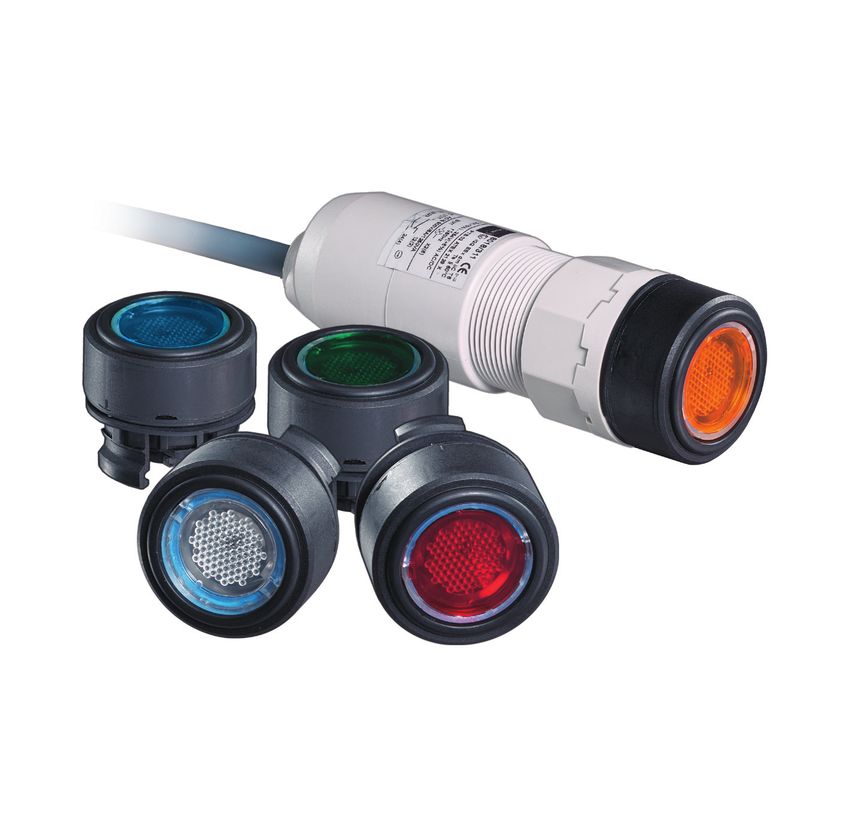
            Luminous colour       Red, yellow, green, blue, white using colour filter (included in delivery)        PL
       Mounting/installation                                                                                        CZ
         Connection               Conductor H05 6 x 0.75 mm2 / 9 x 18 AWG, 6-pole
                                                                                                                    SK
         Conductor length         6 m/236 inch (Standard)
                                                                                                                    HU
                                                                                                                    SL
       For further technical data, see r-stahl.com.                                                                 RO
                                                                                                                    BG
                                                                                                                    LV
                                                                                                                    LT
                                                                                                                    EE
                                                                                                                    CH
                                                                                                                    KR
                                                                                                                    CN

290432 / 8018607300                                                 LED illuminated pushbutton                 13
2021-06-11·IO00·III·en·00                                           for panel mounting
                                                                    Series 8018/3
Appendix B
DE
US
     13    Appendix B
FR   13.1 Dimensions/Fastening Dimensions
IT         Dimensional drawings (all dimensions in mm [inches]) – Subject to change
ES

                                       [0,04 ... 0,26]
                        Ø 38

                                         1,0 ... 6,50
                      [Ø 1,50]
RU
NL
           [0,71]
             18

DK
SE
                                                            104,50 [4,11]

                                      Ø 38,50

FI                                    [Ø 1,52]                                                   42 [1,65]

PT
GR
PL
                     Ø 36,50

CZ
                                                                                                                                   04488E00
                     [Ø 1,44]
                                                                            03315E00

SK         Series 8018/3                                                               Drilling hole pattern:
HU         LED illuminated pushbutton                                                  Aligning several panel mounting devices
                                                                                       with a dia. 38 mm/1.5 inch actuator
SL
RO
            ø 30,50 ±0,1 [ø 1,20±0, 004]
BG
                                                  +0,008]
                                      +0,2

LV
                                 34,20 0

                                             [1,35 0

LT
                   +0,1
                     0,
EE             3,50 0
                 +0,004]
                  0,
           [1,14 0,000
CH                                                                                                                                 16360E00

KR         Punch pattern
CN

     14      LED illuminated pushbutton                                                                          290432 / 8018607300
             for panel mounting                                                                               2021-06-11·IO00·III·en·00
             Series 8018/3
Mode d’emploi pour                      DE
                                                           l’Amérique du Nord                      GB
                                                         Pour d'autres langues, voir r-stahl.com
                                                                                                   CA
                                                                                                   IT
                                                                                                   ES
                                                                                                   RU
                                                                                                   NL
                                                                                                   DK
                                                                                                   SE
                                                                                                   FI
                                                                                                   PT
                                                                                                   GR
                                                                                                   PL
                                                                                                   CZ
                                                                                                   SK
                                                                                                   HU
                                                                                                   SL
                                                                                                   RO
                                                                                                   BG
Bouton-poussoir lumineux à LED                                                                     LV
pour montage encastré                                                                              LT
                                                                                                   EE
                                                                                                   CH
Série 8018/3
                                                                                                   KR
                                                                                                   CN

                                                                  ultérie         ure ! –
                                                     t  ilisation
                                        er pour une u
                            –Àc  onserv
Sommaire
DE
GB
          Sommaire
          1      Indications générales ...........................................................................................3
CA        1.1    Fabricant ..............................................................................................................3
IT        1.2    À propos du présent mode d’emploi ....................................................................3
ES        1.3    Autres documents ................................................................................................3
          1.4    Conformité aux normes et dispositions................................................................3
RU
          2      Explication des symboles.....................................................................................4
NL        2.1    Symboles figurant dans le mode d'emploi ...........................................................4
DK        2.2    Symboles sur le dispositif ....................................................................................4
SE        3      Sécurité................................................................................................................5
          3.1    Utilisation conforme aux fins prévues ..................................................................5
FI
          3.2    Qualification du personnel ...................................................................................5
PT        3.3    Risques résiduels.................................................................................................6
GR        4      Transport et stockage ..........................................................................................7
          5      Montage et installation .........................................................................................8
PL
          5.1    Installation des dispositifs 8018/3 ........................................................................8
CZ        5.2    Installation des dispositifs dans le tableau de commande ...................................8
SK        5.3    Changement des cabochons colorés...................................................................9
HU        6      Mise en service ....................................................................................................9
          7      Maintenance, entretien, réparation ......................................................................9
SL
          7.1    Maintenance ........................................................................................................9
RO        7.2    Entretien...............................................................................................................9
BG        7.3    Réparation ...........................................................................................................9
          8      Retour ................................................................................................................10
          9      Nettoyage...........................................................................................................10
LT        10     Élimination .........................................................................................................10
EE        11     Accessoires et pièces de rechange ...................................................................11
CH        12     Annexe A ...........................................................................................................11
          12.1   Caractéristiques techniques...............................................................................11
KR
          13     Annexe B ...........................................................................................................14
CN        13.1   Cotes / cotes de fixation.....................................................................................14

     2      Bouton-poussoir lumineux à LED
            pour montage encastré
            Série 8018/3
Indications générales
                                                                                                          DE
1       Indications générales                                                                             GB
1.1     Fabricant                                                                                         CA
         R. STAHL Schaltgeräte GmbH               R. STAHL, INC.                                          IT
         Am Bahnhof 30                            13259 N. Promenade Blvd.                                ES
         D-74638 Waldenburg                       Stafford, TX 77477
                                                                                                          RU
         Allemagne                                États-Unis d'Amérique
         Tél. :     +49 7942 943-0                Tél. :         +1 800 782-4357                          NL
         Fax :      +49 7942 943-4333             Fax :          +1 281 313-9302                          DK
         Internet : r-stahl.com                   Internet :     r-stahl.com                              SE
         E-mail :   info@r-stahl.com              E-mail :       sales.us@r-stahl.com
                                                                                                          FI
         R. STAHL Ltd.
         #303, 8925-51 Avenue                                                                             PT
         Edmonton, AB T6E 5J3                                                                             GR
         Canada                                                                                           PL
         Tél. :     +1 877 416 4302
                                                                                                          CZ
         Fax :      +1 780 469 5525
         Internet : r-stahl.com                                                                           SK
         E-mail :   info.ca@r-stahl.com                                                                   HU
                                                                                                          SL
1.2     À propos du présent mode d’emploi
        ▶ Lire attentivement le présent mode d’emploi avant toute utilisation, en particulier les         RO
            consignes de sécurité.                                                                        BG
        ▶ Respecter tous les documents applicables (voir également chapitre 1.3)                          LV
        ▶ Conserver le mode d’emploi pendant la durée de vie du dispositif.
        ▶ Le mode d’emploi doit être à tout moment accessible au personnel opérateur et de                LT
            maintenance.                                                                                  EE
        ▶   Transmettre le mode d’emploi à chaque propriétaire ou utilisateur ultérieur du dispositif.
                                                                                                          CH
        ▶   Mettre à jour le mode d’emploi après réception de tout complément d’information transmis
            par R. STAHL.                                                                                 KR
                                                                                                          CN
         N° d'identification :                                290432 / 8018607300
         Numéro de publication :                              2021-06-11·IO00·III·fr·00

        La notice originale est la version américaine.
        Celle-ci est juridiquement contraignante pour toutes les questions juridiques.

1.3     Autres documents
        • Fiche technique
        Documents en d'autres langues, voir r-stahl.com.

1.4     Conformité aux normes et dispositions
        Certificats États-Unis et Canada : r-stahl.com.

 290432 / 8018607300                                         Bouton-poussoir lumineux à LED         3
 2021-06-11·IO00·III·fr·00                                   pour montage encastré
                                                             Série 8018/3
Explication des symboles
DE
GB
     2     Explication des symboles
CA   2.1   Symboles figurant dans le mode d'emploi
IT         Symbole                            Signification
ES                                            Avis relatif aux travaux plus légers
RU
                                Situation de danger qui, en cas de non-respect des consignes
NL               DANGER !       de sécurité, peut entraîner la mort ou des blessures graves
DK                              avec séquelles irréversibles.
SE                              Situation de danger qui, en cas de non-respect des consignes
                AVERTISSEMENT ! de sécurité, peut entraîner des blessures graves.
FI
                                Situation de danger qui, en cas de non-respect des consignes
PT              ATTENTION !     de sécurité, peut entraîner des blessures légères.
GR
           AVIS !               Situation de danger qui, en cas de non-respect des consignes
PL                              de sécurité, peut entraîner des dégâts matériels.
CZ
     2.2   Symboles sur le dispositif
SK
           Symbole                            Signification
HU
                                              Marque UL, conformité justifiée du produit aux prescriptions en
SL                                            matière de sécurité des États-Unis et du Canada
RO
                                              Entrée
BG
                      15649E00

LV
                                              Sortie
LT
                      15648E00

EE
CH
KR
CN

     4       Bouton-poussoir lumineux à LED                                               290432 / 8018607300
             pour montage encastré                                                      2021-06-11·IO00·III·fr·00
             Série 8018/3
Sécurité
                                                                                                           DE
3       Sécurité                                                                                           GB
        Ce dispositif a été fabriqué selon l’état actuel de la technique.
        Ce faisant, des règles et normes techniques reconnues en matière de sécurité ont été               CA
        respectées.                                                                                        IT
        Néanmoins, le dispositif doit toujours être utilisé de manière adéquate et avec précaution.
                                                                                                           ES
        En effet, une utilisation inappropriée peut mettre en danger l’utilisateur et des personnes
        tierces.                                                                                           RU
        Un endommagement du dispositif, de l'environnement et des biens matériels pourrait                 NL
        également s'ensuivre.
                                                                                                           DK
        ▶ N’utiliser le dispositif que                                                                     SE
            - dans un état irréprochable                                                                   FI
            - pour les fins auxquelles il est destiné (voir chapitre « Utilisation conforme aux fins
                prévues »)                                                                                 PT
            - dans le strict respect du présent mode d’emploi.                                             GR
             Le présent mode d’emploi est fourni à titre d’information uniquement et ne couvre pas         PL
             tous les détails, variations ou combinaisons dans lesquels ces dispositifs sont utilisés,
                                                                                                           CZ
             stockés, expédiés, installés et exploités ou entretenus en toute sécurité.
             Les conditions d'utilisation du produit étant indépendantes de l'entretien, de la             SK
             surveillance et du contrôle assurés par le fabricant, il incombe à l'acheteur de vérifier     HU
             l'adéquation du produit à l'usage qu'il entend en faire et d'assumer tous les risques et la
             responsabilité qui y sont associés.                                                           SL
                                                                                                           RO
3.1     Utilisation conforme aux fins prévues                                                              BG
        Le bouton-poussoir lumineux du type 8018/3 commute des circuits de charge, de commande
        et de signalisation, et indique des états de commande par l’allumage ou l’extinction               LV
        d’un signal lumineux.                                                                              LT
        Il convient pour une installation dans les parois de boîtiers, les couvercles de dispositifs       EE
        électriques et les tableaux ou armoires de commande.
        Il est composé d’une partie principale comprenant 2 éléments de contact à blindage résistant       CH
        à la pression, d’un élément indicateur lumineux avec des diodes luminescentes comme                KR
        source d’énergie ainsi que d’une pièce frontale de commande.
                                                                                                           CN
        L'utilisation du bouton-poussoir lumineux est autorisée en zone Ex de la classe I, div. 2 et
        classe I, zone 1.

3.2     Qualification du personnel
        Tous les travaux sur le dispositif ne doivent être exécutés que par un technicien qualifié.
        Ceci s’applique en particulier aux travaux relevant des domaines suivants :
        • Sélection de produits, conception et modification
        • Montage/démontage du dispositif
        • Installation
        • Mise en service
        • Maintenance, réparation, nettoyage

        Le technicien qualifié chargé de l'exécution de ces travaux doit connaître les normes et
        dispositions nationales pertinentes en matière d'électrotechnique.

        Des connaissances supplémentaires sont requises pour les opérations exécutées en
        zone Ex ! R. STAHL recommande le niveau de connaissances décrit dans les normes
        pertinentes.

 290432 / 8018607300                                          Bouton-poussoir lumineux à LED          5
 2021-06-11·IO00·III·fr·00                                    pour montage encastré
                                                              Série 8018/3
Sécurité
DE
     3.3    Risques résiduels
GB
CA   3.3.1 Risque d’explosion
IT         Il est impossible d’exclure entièrement le risque d’explosion en zone Ex.

ES          ▶ Toujours exécuter toutes les opérations en zone Ex avec le plus grand soin !
RU
            Les dangers éventuels (« risques résiduels ») peuvent être différenciés en fonction de leur
NL
            cause :
DK
SE          Endommagement du dispositif
            Pendant le transport, le montage ou la mise en service, le dispositif peut être déformé,
FI
            cabossé ou rayé. De ce fait, il pourrait devenir non étanche. Un joint endommagé est
PT          susceptible d’annuler partiellement ou entièrement la protection antidéflagrante du dispositif.
GR          Il pourrait s’ensuivre des explosions entraînant des blessures graves ou mortelles.
            Pour éviter ces risques, respecter les mesures de sécurité suivantes :
PL          ▶ Transporter le dispositif uniquement dans son emballage d’origine ou un emballage
CZ              équivalent.
SK          ▶ Contrôler l’absence de dommages sur l’emballage et le dispositif. Signaler immédiatement
                des dommages éventuels à R. STAHL.
HU          ▶ Conserver le dispositif dans son emballage original, au sec (sans condensation),
SL              dans une position stable et à l’abri des secousses.
RO
            Surchauffe ou charge électrostatique
BG          Une transformation ultérieure ou l'application d'une peinture peut modifier l'état du dispositif,
LV          à tel point que sa protection antidéflagrante s'en trouve compromise. Un nettoyage
            inapproprié peut également entraîner une surchauffe du dispositif ou y générer des charges
LT
            électrostatiques. Des étincelles pourraient en résulter. Il pourrait s’ensuivre des explosions
EE          entraînant des blessures graves ou mortelles. Pour éviter ces risques, respecter les mesures
CH          de sécurité suivantes :
            ▶ N’utiliser le dispositif que dans les conditions de fonctionnement prévues
KR             (voir le marquage sur le dispositif et le chapitre « Caractéristiques techniques »).
CN
            Joint endommagé (détérioration de la protection IP)
            Le degré de protection IP indique une étanchéité correcte des matériels.
            Toute modification de construction, par ex. le perçage de trous, ou un montage incorrect peut
            engendrer une détérioration de l’indice de protection IP du dispositif. Il pourrait s’ensuivre des
            explosions entraînant des blessures graves ou mortelles.
            ▶ Toute modification apportée au dispositif ne doit être exécutée que conformément aux
               instructions du présent mode d'emploi. Toute modification doit être contrôlée et validée
               par R. STAHL ou un organisme de contrôle certifié (3rd party inspection).
            ▶ Effectuer la maintenance ainsi que les réparations du dispositif uniquement avec des
               pièces de rechange d'origine. Consulter R. STAHL au préalable.

     6          Bouton-poussoir lumineux à LED                                            290432 / 8018607300
                pour montage encastré                                                   2021-06-11·IO00·III·fr·00
                Série 8018/3
Transport et stockage
                                                                                                         DE
        Installation, mise en service et maintenance inappropriées
        Les tâches susmentionnées doivent exclusivement être exécutées conformément aux                  GB
        dispositions nationales en vigueur dans le pays d’utilisation. Autrement, la protection          CA
        antidéflagrante peut être annulée. Il pourrait s’ensuivre des explosions entraînant des          IT
        blessures graves ou mortelles. Pour éviter ces risques, respecter les mesures de sécurité
        suivantes :                                                                                      ES
        ▶ Le montage, l’installation, la mise en service et la remise en état ne doivent être exécutés   RU
           par du personnel qualifié et autorisé (voir chapitre 3.2).
                                                                                                         NL
        ▶ Toute modification apportée au dispositif ne doit être exécutée que conformément aux
           instructions du présent mode d'emploi. Toute modification doit être contrôlée et validée      DK
           par R. STAHL ou un organisme de contrôle certifié (3rd party inspection).                     SE
        ▶ Effectuer la maintenance ainsi que les réparations du dispositif uniquement avec des
                                                                                                         FI
           pièces de rechange d'origine. Consulter R. STAHL au préalable.
                                                                                                         PT
3.3.2 Risque de blessure
                                                                                                         GR
        Choc électrique                                                                                  PL
        Lors du fonctionnement, le dispositif est temporairement soumis à des tensions élevées.          CZ
        Le contact avec des pièces conductrices sous tension peut entraîner des chocs électriques
        graves, générant ainsi des blessures sévères.                                                    SK
        ▶ Utiliser le dispositif uniquement avec un matériel à tension interne conformément au           HU
           chapitre « Caractéristiques techniques ».                                                     SL
        ▶ Raccorder les circuits électriques uniquement aux bornes adaptées à cet effet.
        ▶ Couper l'alimentation électrique avant de procéder à l'installation ou la maintenance de       RO
           ces dispositifs.                                                                              BG
                                                                                                         LV
4       Transport et stockage                                                                            LT
        ▶ Transporter et stocker le dispositif avec précaution et dans le respect des consignes de       EE
            sécurité (voir chapitre « Sécurité »).
                                                                                                         CH
                                                                                                         KR
                                                                                                         CN

 290432 / 8018607300                                        Bouton-poussoir lumineux à LED          7
 2021-06-11·IO00·III·fr·00                                  pour montage encastré
                                                            Série 8018/3
Montage et installation
DE
GB
     5      Montage et installation
            ▶ Monter le dispositif avec précaution et uniquement dans le respect des consignes de
CA              sécurité (voir chapitre « Sécurité »).
IT          ▶   Lire attentivement et respecter avec précision les instructions de montage suivantes.
ES   5.1    Installation des dispositifs 8018/3
RU
NL          Découper les ouvertures
            ▶ Découper l'ouverture selon le dessin ci-dessous.
DK            Ces dispositifs peuvent être installés dans des murs d'une épaisseur de
SE            1,0 ... 6,5 mm / 0.04 ... 0.26 inch.
FI
            ▶ Respecter les distances.
PT          Retirer l'actionneur du bloc de contact
GR          ▶ Tourner autant que possible l'écrou à embase dans le sens antihoraire.
            ▶ Retirer l'actionneur.
PL
CZ          Toutes les dimensions en mm [pouces]
SK                                                42 [1,65]

HU
                              [0,67]
                                17

SL
RO                                     21115E00               20941E00

BG
LV   5.2    Installation des dispositifs dans le tableau de commande
LT
EE
CH
KR
CN                                                                                                              04928E00

            ▶ Placer la tête de commande du bouton-poussoir lumineux (1) dans la paroi de
                montage (3) et la bloquer. Veiller à l'ajustement correct du joint (2).
            ▶ Insérer le bouton-poussoir lumineux par l'arrière sur la tête de commande (1) de celui-ci.
                Veiller à ce que le bouton-poussoir lumineux et la tête de commande (1) soient solidement
                fixés dans la paroi de montage (3).
            ▶   Serrer à fond la tête de commande du bouton-poussoir lumineux (1) avec l’écrou fileté (4)
                contre la paroi de montage (3). (Couple de serrage de l’écrou fileté : 2,5 Nm / 0.28 lb/inch)
            ▶   Insérer la lentille de couleur correspondant à la couleur lumineuse souhaitée.

     8          Bouton-poussoir lumineux à LED                                              290432 / 8018607300
                pour montage encastré                                                     2021-06-11·IO00·III·fr·00
                Série 8018/3
Mise en service
                                                                                                                  DE
5.3     Changement des cabochons colorés
                                                                                                                  GB
                                                                                                                  CA
                                                                                                                  IT
                                                                                                                  ES
                                                                                                                  RU
                                                                                                                  NL
                                                                                                                  DK
                                                                                                       11465E00

        ▶ Positionner un tournevis plat entre la touche et la lentille de couleur et soulever la
            lentille de couleur pour la sortir de sa fixation.                                                    SE
        ▶ Retirer la lentille de couleur.                                                                         FI
        ▶ Encliqueter la nouvelle lentille de couleur.
                                                                                                                  PT
                                                                                                                  GR
6       Mise en service                                                                                           PL
        Avant la mise en service, effectuer les vérifications suivantes :
        ▶ Vérifier si le boîtier est endommagé.                                                                   CZ
        ▶ Vérifier la bonne exécution du montage et de l'installation.                                            SK
        ▶ Le cas échéant, retirer les corps étrangers.                                                            HU
        ▶ Le cas échéant, nettoyer la chambre de connexion.
        ▶ Vérifier si les couples de serrage prescrits sont respectés.                                            SL
                                                                                                                  RO

7       Maintenance, entretien, réparation                                                                        BG
        ▶ Observer les normes et réglementations en vigueur dans le pays d’utilisation.                           LV
                                                                                                                  LT
7.1     Maintenance
        En complément des réglementations nationales, vérifier en outre les points suivants :                     EE
        • le serrage correct des vis de connexion,                                                                CH
        • la formation de fissures et d’autres dommages visibles sur le boîtier du dispositif et/ou le
                                                                                                                  KR
          boîtier de protection,
        • le respect des températures admissibles,                                                                CN
        • le bon ajustement des fixations,
        • une utilisation conforme aux fins prévues.

7.2     Entretien
        ▶ L'entretien du dispositif doit être assuré dans le respect des dispositions nationales en
            vigueur et conformément aux consignes de sécurité définies dans le présent mode
            d'emploi (chapitre « Sécurité »).
        ▶   La seule mesure d'entretien consiste en un contrôle régulier de la présence de dommages
            et du bon fonctionnement.

7.3     Réparation
        ▶ Les réparations du dispositif ne doivent être réalisées que par la société R. STAHL.
        ▶ Des composants de dispositif défectueux ou un dispositif endommagé doivent être
            remplacés immédiatement pour garantir la sécurité électrique et une protection optimale
            du système contre les explosions.

 290432 / 8018607300                                             Bouton-poussoir lumineux à LED           9
 2021-06-11·IO00·III·fr·00                                       pour montage encastré
                                                                 Série 8018/3
Retour
DE
GB
     8        Retour
              ▶ Tout retour ou emballage de dispositifs ne doit être effectué qu'en accord avec R. STAHL !
CA                 À cet effet, veuillez contacter le représentant local de R. STAHL.
IT
              Le service après-vente de R. STAHL se tient à disposition en cas de retour de dispositif pour
ES
              réparation ou maintenance.
RU
NL            ▶ Contacter personnellement le service après-vente.
DK
              ou
SE
FI            ▶ Consulter le site Internet r-stahl.com.
              ▶ Sélectionner dans « Assistance » > « RMA » > « Formulaire RMA ».
PT            ▶ Remplir le formulaire et l'envoyer.
GR                 Vous recevrez automatiquement par e-mail un formulaire RMA.
PL                 Veuillez imprimer ce fichier.
              ▶    Envoyer ensemble dans l'emballage le dispositif et le formulaire RMA à la
CZ                 R. STAHL Schaltgeräte GmbH (adresse indiquée à la chapitre 1.1).
SK
HU
     9        Nettoyage
SL            ▶ Vérifier le bon état du dispositif avant et après le nettoyage. Mettre immédiatement hors
RO                 service les dispositifs endommagés.
              ▶ Nettoyer le dispositif exclusivement avec un chiffon humide.
BG
              ▶ En cas de nettoyage humide, utiliser de l’eau ou des détergents doux, non abrasifs,
LV                 non agressifs.
LT            ▶ Ne pas utiliser de détergents ou solvants agressifs.
              ▶ Ne jamais nettoyer le dispositif avec un jet d’eau puissant, par ex. un nettoyeur haute
EE                 pression !
CH
KR
     10       Élimination
CN            ▶ Respecter les prescriptions nationales et locales ainsi que les dispositions légales
                   relatives à l'élimination.
              ▶    Les matériaux doivent être recyclés séparément.
              ▶    S'assurer d’une élimination de tous les composants respectueuse de l'environnement
                   conformément aux dispositions légales.

     10           Bouton-poussoir lumineux à LED                                          290432 / 8018607300
                  pour montage encastré                                                 2021-06-11·IO00·III·fr·00
                  Série 8018/3
Accessoires et pièces de rechange
                                                                                                                        DE
11      Accessoires et pièces de rechange                                                                               GB
         AVIS ! Dysfonctionnement ou endommagement du dispositif si les pièces utilisées ne sont
                                                                                                                        CA
         pas d'origine.
         Le non-respect peut causer des dégâts matériels.                                                               IT
         ▶ Utiliser uniquement des pièces de rechange et des accessoires d’origine de                                   ES
           R. STAHL Schaltgeräte GmbH (voir fiche technique).
                                                                                                                        RU
         Position                Image                 Description                           Numéro de catalogue
                                                                                                                        NL
         Tête de commande                              pour bouton-poussoir lumineux         155163
                                                       (à rappel)                                                       DK
                                            05044E00                                                                    SE
         Pièce d'obturation                            pour obturer les orifices de couvercle 155329                    FI
                                                       non utilisés Ø 30,5 mm
                                            05647E00
                                                                                                                        PT
         Filtre de couleur                             pour bouton-poussoir lumineux blanc   155877                     GR
                                                       pour bouton-poussoir lumineux rouge   155882
                                                       pour bouton-poussoir lumineux jaune   155885                     PL
                                            17596E00
                                                       pour bouton-poussoir lumineux vert    155888                     CZ
                                                       pour bouton-poussoir lumineux bleu    155891
                                                                                                                        SK
        (Images similaires)
                                                                                                                        HU
                                                                                                                        SL
12      Annexe A
                                                                                                                        RO
12.1 Caractéristiques techniques                                                                                        BG

        Voir les caractéristiques techniques du dispositif.                                                             LV
         Protection contre les explosions                                                                               LT
         États-Unis (NEC)/Canada (CEC)                                                                                  EE
           NEC et CEC
                                                                                                                        CH
                                                                                                                        KR
                                 Fichier n° E182378                                                                     CN
                                 Ex e
                                 Classe I, zone 1, AEx d mb IIC T6
                                 Classe I, zone 1, Ex d mb IIC T6 Gb
                                 Classe I, div. 2, groupes A, B, C et D

                                 Fichier n° E81680
                                 Ex i
                                 Classe I, div.1, groupes A, B, C et D T4
                                 Classe I, zone 0, AEx ia IIB T4, Ex ia IIB T4
                                 Classe I, zone 1, AEx ia IIC T4, Ex ia IIC T4

 290432 / 8018607300                                                      Bouton-poussoir lumineux à LED           11
 2021-06-11·IO00·III·fr·00                                                pour montage encastré
                                                                          Série 8018/3
Annexe A
DE
          Caractéristiques techniques
GB
          Caractéristiques électriques
CA          Tension assignée
IT          d’emploi
ES             Élément de contact max. 500 V
               Partie voyant        Ex e : 12 (-10 %) ... 240 (+10 %) V AC / DC
RU             lumineux             Ex i : Ui = 10,8 ... 28 V DC
NL          Courant de service
DK          assigné
               Élément de contact Ex e : max. 6 A,
SE
                                    Ex i : Ii = ≤ 100 mA
FI             Partie voyant        Ex e : 15 mA à 24 V DC / 2,5 mA à 250 V
PT             lumineux             Ex i : 12 mA à 10,8 V DC / 18 mA à 28 V DC
            Fréquence               0 ... 60 Hz
GR
            Puissance assignée 0,6 W
PL          d'emploi
CZ          Schéma de câblage Exemple de conception
                                    avec câble :
SK
                                    les chiffres entre
HU                                  parenthèses sont les
                                    numéros des
SL                                  conducteurs
RO
                                    (1)   (3)   (5)              (1)   (3)   (5)              (1)   (3)   (5)
BG                                  11    23    X1               11    21    X1               13    23    X1

LV                                  12    24    X2               12    22    X2               14    24    X2
                                    (2)   (4)   (6)              (2)   (4)   (6)              (2)   (4)   (6)
LT                                                    09770E00                     09772E00                 09771E00

                                   8018/3113                  8018/3123                  8018/3133
EE
            Puissance de           Catégorie d'utilisation
CH          commutation            AC-15                      AC-12                      DC-13
KR                                 500 V                      500 V                      110 V
CN                                 max. 6 A                   max. 6 A                   max. 1 A
                                   max. 1250 VA               max. 3000 VA               max. 110 W
                                   Valeurs limites nominales en fonction des catégories d’utilisation
            Tension minimale*      12 V AC / DC
            Courant minimal*       50 mA
                                   * Valeurs indicatives en fonction des conditions d'exploitation
          Conditions ambiantes
            Température            -30 ... +60 °C T6 / -22 ... +140 °F T6
            ambiante               (La température de stockage correspond à la température ambiante)

     12     Bouton-poussoir lumineux à LED                                                       290432 / 8018607300
            pour montage encastré                                                              2021-06-11·IO00·III·fr·00
            Série 8018/3
Annexe A
                                                                                                                      DE
        Caractéristiques techniques
                                                                                                                      GB
        Caractéristiques mécaniques
          Degré de protection IP65 selon NEMA ANSI/CEI 60529 ; CSA-C22.2 n° 60529
                                                                                                                      CA
          Matériau                                                                                                    IT
            Boîtier              Polyamide                                                                            ES
            Filtre de couleur    Polyamide
                                                                                                                      RU
            Matériau de contact
                                                                                                                      NL
               Standard          Argent-nickel
               Spécial           Argent-nickel, doré                                                                  DK
          Durée de vie                                                                                                SE
            Élément de contact 106 cycles de manœuvres                                                                FI
            Partie voyant        105 heures de service
            lumineux                                                                                                  PT
          Voyant lumineux                                                                                             GR
            Lampe                LED blanche                                                                          PL
            Couleur lumineuse rouge, jaune, vert, bleu, blanc par filtre de couleur (inclus dans la livraison)
                                                                                                                      CZ
        Montage / Installation
                                                                                                                      SK
          Raccordement           Conducteur H05 6 x 0,75 mm2 / 9 x 18 AWG, 6 pôles
          Longueur de câble      6 m / 236 inch (standard)                                                            HU
                                                                                                                      SL
                                                                                                                      RO
       Pour d'autres caractéristiques techniques, voir r-stahl.com.
                                                                                                                      BG
                                                                                                                      LV
                                                                                                                      LT
                                                                                                                      EE
                                                                                                                      CH
                                                                                                                      KR
                                                                                                                      CN

290432 / 8018607300                                                Bouton-poussoir lumineux à LED                13
2021-06-11·IO00·III·fr·00                                          pour montage encastré
                                                                   Série 8018/3
Annexe B
DE
GB
     13    Annexe B
CA   13.1 Cotes / cotes de fixation
IT         Plans d'encombrement (toutes les dimensions sont en mm [pouces]) –
ES         Sous réserve de modifications
RU

                                       [0,04 ... 0,26]
                        Ø 38

                                         1,0 ... 6,50
                      [Ø 1,50]
NL
           [0,71]

DK
             18

SE
                                                            104,50 [4,11]

FI                                    Ø 38,50
                                      [Ø 1,52]                                                   42 [1,65]
PT
GR
PL
CZ                    Ø 36,50
                                                                                                                                   04488E00
                      [Ø 1,44]
SK                                                                          03315E00

HU         Série 8018/3                                                                Plan de perçage :
           Bouton-poussoir lumineux à LED                                              installation en rangée de plusieurs
SL                                                                                     boutons-poussoirs encastrables avec
RO                                                                                     Ø de la tête de commande 38 mm / 1.5 inch
BG
LV          ø 30,50 ±0,1 [ø 1,20±0, 004]
                                                  +0,008]

LT
                                      +0,2
                                 34,20 0

                                             [1,35 0

EE
CH                  +0,1
                3,50 0
                      0,

KR                +0,004]
                   0,
            [1,14 0,000
                                                                                                                                   16360E00
CN
           Image de découpe

     14       Bouton-poussoir lumineux à LED                                                                    290432 / 8018607300
              pour montage encastré                                                                           2021-06-11·IO00·III·fr·00
              Série 8018/3
You can also read