Volare Gas-fired pizza oven - MVP Group Corp
←
→
Page content transcription
If your browser does not render page correctly, please read the page content below
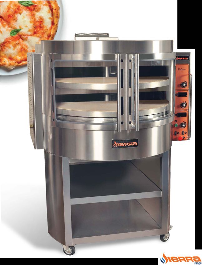
Volare Gas-fired pizza oven

                                                       Installation
                                                         operation
                                                               and
                                                      maintenance
                                                           manual

     5659 Royalmount Ave.                  3560 NW 56th St.
                                           Fort Lauderdale, FL 33309 USA
     Montreal, QC H4P2P9 CANADA            Telephone: (786) 600-4687
     Telephone: (514) 737-9701             Toll Free Telephone: 1-844-218-8477
     Toll Free Telephone: 1-888-275-4538   Fax: (786) 661-4100
     Fax: (514) 342-3854                   Email: service@mvpgroupcorp.com

     For service call 1-888-275-4538
READ THESE SAFETY PRECAUTIONS FIRST

                              WARNING:
POST IN A PROMINENT LOCATION INSTRUCTIONS TO BE FOLLOWED
IN THE EVENT YOU SMELL GAS.     THIS INFORMATION SHALL BE
OBTAINED BY CONSULTING YOUR LOCAL GAS SUPPLIER.

                              WARNING:
This appliance is only for professional use and shall be used only by
qualified people. All parts that have been protected by the manufacturer
or his agent must not be adjusted by the end user.

                          FOR YOUR SAFETY
Do not store or use gasoline or other flammable vapors or liquids in the
vicinity of this or any other appliance.

                              WARNING:
Improper installation, adjustment, alternation, service or maintenance
can cause property damage, injury or death. Refer to these instructions
thoroughly before installing or servicing this equipment.

IN THE EVENT OF A POWER FAILURE DO NOT ATTEMPT TO OPERATE
THIS DEVICE. SHUT OFF POWER

 Please read this manual carefully and retain it for future reference

The information contained in this manual is important for the proper
installation, use, and maintenance of this oven

Adherence to these procedures and instructions will result in
satisfactory baking results and long, trouble free service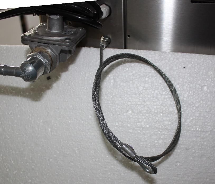
Customer Information
MODEL NUMBER: ________________________
SERIAL NUMBER: _________________________
PURCHASE DATE: _________________________
DISTRIBUTOR:
____________________________________________________
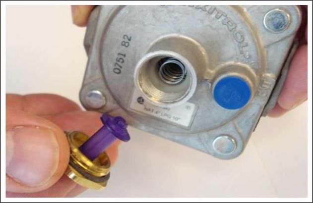
TABLE OF CONTENTS
1       Description and specifications
1.1     About this manual      …………………………………………………………                    1
1.2     General safety instructions ………………………………….....................   1
1.3     Oven description ..…………………………………………………………...                     1
1.4     Dimensions …………………………………………………………………...                          2
1.5     Gas ratings …..………………………………………………………………                          3
1.6     Technical Data ……………………………………………………………….                         3

2       Installation
2.1     Delivery and inspection ……………………………………………………..                   4
2.2     Unpacking ……………………………………………………………………                             4
2.3     Assembly ……………………………………………………………………..                            4
2.4     Location – Clearances ……………………………………………………….                     5
2.5     Gas connection ……………………………………………………………….                         6
2.6     Air supply ……………………………………………………………………...                         7
2.7     Electrical connection …………………………………………………………                     7
2.8     Adjustments …………………………………………………………………..                          8

3       Operation
3.1     Safety …………………………………………………………………………. 9
3.2     Location and description of controls ………………………………………. 10
3.3     Before first use ………………………………………………………………. 10
3.4     Starting the oven …………………………………………………………….. 11
3.5     Turning oven off ……………………………………………………………… 11
3.6     Using Volare oven ……………………………………………………………... 12
3.7     Baking ………………………………………………………………………… 12

4       Maintenance
4.1     Safety …………………………………………………………………………                              13
4.2     Daily maintenance ……………………………………………………………                        13
4.3     Weekly maintenance ………………………………………………………...                      14
4.4     Monthly maintenance ………………………………………………………..                      14
4.5     Lubrication ……………………………………………………………………..                         14

5       Service and conversions
5.1     Pressure control ……………………………………………………………...                      15
5.1.2   Inlet pressure checking ………....……………………………………………                 15
5.1.3   Outlet pressure checking …………..……………………………………….                  15
5.2     Adjustment to a different type of gas ………………………………………            16
5.2.1   Adjustment of the main burner ……………………………………………...               16
5.2.2   Adjustment of the pilot burner ………………………………………………                16
5.3     Adjustment of the pressure regulator ………………………………………             17

TABLE OF CONTENTS

6   Trouble Causes and corrective measures   18

7   Appendix 1 - Parts List                  19

8   Appendix 2 - Electrical wiring diagram   20
Description and specifications

1.1. About this manual
This manual includes all the information, advises and warnings for the correct use of Volare gas ovens with
rotating deck and is supplied with every product. The manual is a part of the machine. Before any action of
installation, use or maintenance, read the corresponding chapters carefully.
This manual must be kept in safe place where it should be easily accessible. In case you sell the oven, you
must deliver it to the new owner together with the machine.

1.2. General safety instructions
This appliance is manufactured for professional use and must be used only by specialized personnel. All
works for the installation, gas supply connections, repairs and extensive maintenance must be done by
qualified technicians.
Incorrect handling of this product could possibly result in personal injury or physical damage. The
manufacturer assumes no responsibility for any damage caused by mishandling that is beyond normal
usage defined in this manual of this gas oven.
Before using or working on the appliance is necessary to know the operation of every control mentioned in
this manual.
After any action of routine maintenance be sure that all parts of the appliance have been replaced correctly
and are in condition to operate normally.

1.3. Oven description
Gas heated oven Volare is professional machine used to bake food and especially pizza or pastries in big
quantities. It is equipped with two rotating decks made of ceramic material proper for contact with food. The
front side of the machine may be open and, in combination with the ability to rotate, allows easy access
and inspection of the baking procedure.
Each deck is heated by two high output, low emission gas burners, one under and one above it. Each
burner is controlled by independent thermostatic valve and safety device with thermocouple. The frame of
the appliance is made of stainless steel and is mounted on table with casters to allow easy moving and
positioning in the working area.

                                                      1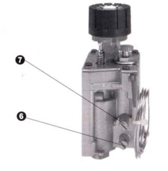
Description and specifications
1.4. Dimensions

                          2
Description and specifications
1.5. Gas ratings
Natural Gas Propane Gas LP
Input Manifold Pilot Input Manifold Pilot
Burner Burner
Rate Pressure Burner Rate Pressure Burner
Orifice Orifice
(BTU/hr) (iwc) Orifice (BTU/hr) (iwc) Orifice
Bottom 0.0925 in 0.0114 in 0.059 in 0.00945 in
30000 5 30000 10
burner (2.35 mm) (0.29 mm) (1.50 mm) (0.24 mm)
Middle 0.0925 in 0.0114 in 0.059 in 0.00945 in
30000 5 30000 10
burner (2.35 mm) (0.29 mm) (1.50 mm) (0.24 mm)
Top 0.0925 in 0.0114 in 0.059 in 0.00945 in
30000 5 30000 10
burner (2.35 mm) (0.29 mm) (1.50 mm) (0.24 mm)
1.6. Technical Data
Width 50-3/10’’ (1280 mm)
Depth 46-3/5’’ (1186 mm)
Height - with base 68-1/4’’ (1733 mm)
Weight (Lb) 550
Deck’s diameter 38-3/16"970 mm
Rotation speed 0.8 - 4 RPM.
Electric power supply 115 V ~ 60Hz
Electric power consumption 130 Watt
Total heating power (BTU/h) 90000
3Installation
2.1 Delivery and inspection
All Volare ovens are produced with quality workmanship and material. They are packed properly to prevent
damage and they are inspected before leaving the factory. Upon delivery inspect the shipping container for
external damage. Immediately after unpacking, check for external or internal damage. If any part is found to
be damaged, save the packaging material and contact the appropriate persons immediately to fill a
damaged claim.
2.2 Unpacking
All Volare ovens with rotating deck are delivered together with a wheeled base. The oven is packed in a
wooden container and the base is fixed on the top, wrapped in cardboard. When you have all the crates
unloaded, unpack and remove all packing material.
To avoid scratching the highly polished exterior surface of this equipment whilst in transit, the protective
film on the exterior surfaces has NOT been removed. It is IMPORTANT that this protective film is peeled off
before the equipment is used. Keep the telescopic sponge, supplied for oven’s cleaning, in safe and easily
accessible place near the oven.
Do not reject in environment plastic or metal parts or other dangerous objects. Move the components
inside, near the area where they will be assembled, in the order in which they will be assembled.
2.3 Assembly
Place the wheeled base near the final location.
Leave at least 3 ft (90 cm) around to have
enough space to do the preparation works.
Press the foot pedal on the two front casters to
lock the brakes and secure the base.
Lift carefully the oven and put it on the base. Be
sure that the front side of the oven is placed in
accordance with the front side of the base (open
side).
Place the supporting bar according the sketch so
that its holes correspond to the holes on the base
and the oven.
Attach the screws and tight to secure the oven on
the base.
4Installation
2.4 Location - Clearances
This appliance must be installed with a restraint cable to guard against transmission of strain to the gas
connector. The restraint should be attached without damaging the building.
DO NOT use the gas piping or electrical conduit for the attachment of the permanent end of the
restraint!
Use anchor bolts in
concrete or cement block.
On wooden walls, drive
heavy duty wood lag
screws into the studs of
the wall.
One end of the cable is
anchored to the oven just
beside the gas inlet, while
the other is anchored to
the wall.
After connecting the restraint cable, move the oven to its final location. Then, lock the two front casters.
WARNING! If the restraint must be disconnected during maintenance or cleaning, it must be
reconnected after the oven has been returned to its originally installed position.
The equipment area must be kept free and clear of combustible substances. When installed, minimum
clearances from combustible and non-combustible construction must be 4" (10 cm) at the sides and rear.
Above and around the Oven Front Area the integral clearance must be of 12 inches (30 cm). A minimum
front clearance of 30" (76 cm) is required.
The installation location must allow adequate clearances for servicing. Be sure that restrain cable allows a
clearance of 30 inches (76 cm) to the righthand and back side for this purpose.
Minimum clearances
From combustibles From non-combustibles For servicing
Control box (L) end 4" (10 cm) 4" (10 cm) 30" (76 cm)
Right-hand (R) end 4" (10 cm) 4" (10 cm) 4" (10 cm)
Rear 4" (10 cm) 4" (10 cm) 30" (76 cm)
Above 12" (30 cm) 12" (30 cm) 12" (30 cm)
5Installation
Do not obstruct the flow of combustion and ventilation air. Adequate clearance for air opening into the
combustion chamber must be provided.
Do not permit fans to blow directly at the pizza oven. Wherever possible, avoid open windows next to the
pizza oven. Avoid wall-type fans which create air cross currents within the room.
2.5 Gas connection
THE INSTALLATION INSTRUCTIONS CONTAINED HEREIN ARE FOR THE USE OF QUALIFIED
INSTALLATION AND SERVICE PERSONNEL ONLY. GAS CONNECTION OR SERVICE BY OTHER
THAN QUALIFIED PERSONNEL MAY RESULT IN DAMAGE TO THE OVEN AND/OR INJURY TO THE
OPERATOR.
To have safe and satisfactory operation of this oven installation must conform with local codes, or in the
absence of local codes, with the National Fuel Gas Code, ANSI Z223.1/NFPA 54, or the Natural Gas and
Propane Installation Code, CSA B149.1, as applicable, including:
The installation shall be made with a connector that complies with the Standard for Connectors for Movable
Gas Appliances, ANSI Z21.69 • CSA 6.16, and a quick-disconnect device that complies with the Standard
for Quick-Disconnect Devices for Use With Gas Fuel, ANSI Z21.41 • CSA 6.9
1. The oven and its individual shut off valve must be disconnected from the gas supply piping system
during any pressure testing of that system at test pressures in excess of ½ psig (3.45kPa).
2. The oven must be isolated from the gas supply piping system by closing its individual manual shut off
valve during any pressure testing of the gas supply system at test pressures equal to or less than ½ psig
(3.45kPa)
Installation shall be made with a gas connector that complies with local codes for connectors for movable
gas appliances, and a quick-disconnect device that complies with local codes for such devices in use with
gas fuel.
Locating the gas valve, quick connect hose and electrical outlet near the oven, will allow easier access for
any service visits. This improved access should make any necessary service quicker resulting in less
kitchen disruption. It will also allow easier disconnection of electricity, gas, and restraints for cleaning
around and behind the oven.
Calculations for pipe sizing must take into account the maximum usage rate of all other appliances in the
kitchen or one or more of the appliances will suffer from inadequate or dangerous performance. The 1/2"
internal piping for the oven is generously sized for use in this oven. However, unless the oven installation
is within 10 feet of the main building gas supply, the supply must be larger. For each oven, a 3/4" NPT
flexible quick connect hose and full port gas shut-off valve is recommended as a MINIMUM. The main pipe
supplying each oven branch may need to be larger depending on the number of appliances serviced, the
number of elbows in the piping, and the pressure.
6Installation
2.6 Air supply
WARNING: Failure to properly vent the oven can be hazardous to the health of the operator and
may result in operational problems, unsatisfactory baking and possible damage to the equipment.
Damage sustained as a direct result of improper ventilation will not be covered by the
Manufacturer’s warranty.
This oven must be installed in a ventilated area in accordance with local regulations. It requires make-up air
to replace combustion air and excess air taken out by flue. The oven may be vented using either a
mechanically driven, canopy type, exhaust hood, or a direct flue arrangement.
Ventilation system and HVAC installation must meet local codes to gain approval by the authority having
jurisdiction. Requirements may vary depending on the location. Obtain information from the authority
having jurisdiction to determine the requirements for your installation. Obtain information and review copies
of codes or documents that will be used to inspect and approve your installation.
The rate of air flow exhausted through the ventilation system may vary depending on the oven
configuration and hood design. Consult the hood manufacturer or ventilation engineer for these
specifications. To avoid a negative pressure condition in the kitchen area, return air must be brought back
to replenish the air that was exhausted. A negative pressure in the kitchen can cause heat-related
problems to the oven components as if there were no ventilation at all.
NOTE: Return air from the mechanically driven system must not blow at the opening of the baking
chamber. This will result poor oven baking performance.
Other ventilation concerns
• Special locations, conditions, or problems may require the services of a ventilation engineer or specialist.
• Inadequate ventilation can inhibit oven performance.
• It is recommended that the ventilation system and duct work be checked at prevailing intervals as
specified by the hood manufacturer and/or HVAC engineer or specialist.
2.7. Electrical connection
Before installation check data plate at the front of the unit to ensure appliance is suitable for electric power
supply available.
The oven, when installed, must be electrically grounded in accordance with local codes, or in the absence
of local codes, with the National Electrical Code, NFPA 70, or the Canadian Electrical Code, CSA C22.2, as
applicable.
Wiring diagram is attached in the unit on the back column behind the motor.
7Installation
2.8 Adjustments
ADJUSTMENTS ASSOCIATED WITH INITIAL INSTALLATION
Each oven, and its component parts, have been thoroughly tested and inspected prior to shipment.
However, it is often necessary to further test or adjust the oven as part of a normal and proper installation.
These adjustments are the responsibility of the installer, or dealer. Since these adjustments are not
considered defects in material or workmanship, they are not covered by the Original Equipment Warranty.
They include, but are not limited to:
• adjustment of the doors
• tightening of fasteners
• leveling
• burner adjustments
• testing of gas pressure
No installation should be considered complete without proper inspection, and if necessary, adjustment by
qualified installation or service personnel.
8Operation
3.1 Safety
The information contained in this section is provided for the use of qualified operating personnel. Qualified
operating personnel are those who have carefully read the information contained in this manual, are
familiar with the functions of the oven and/or have had previous experience with the operation of the
equipment described. Adherence to the procedures recommended herein will assure the achievement of
optimum performance and long, trouble-free service.
Please take the time to read the following safety and operating instructions. They are the key to the
successful operation of your oven.
What to do if you smell gas:
• DO NOT try to light any appliance.
• DO NOT touch any electrical switches.
• Use an exterior phone to call your gas supplier immediately.
• If you cannot reach your gas supplier, call the fire department.
What to do in the event of a power failure:
• Turn all switches to off.
• DO NOT attempt to operate the oven until the power is restored.
NOTE: In the event of a shut-down of any kind, allow a five (5) minute shut off period before attempting to
restart the oven.
General safety tips:
• DO NOT use tools to turn off the gas control. If the gas cannot be turned off manually do not try to repair
it. Call a qualified service technician.
• If the oven needs to be moved for any reason, the gas must be turned off and disconnected from the unit
before removing the restraint cable. Reconnect the restraint after the oven has been returned to its original
location.
• DO NOT remove the control panel cover unless the oven is unplugged.
9Operation
3.2 Location and description of controls
All operations for loading/unloading and controlling baking procedure are executed from the front side.
1) Thermostatic gas valve
2) Igniter
3) Motor switch
4) Lighting switch
5) Emergency stop
6) Thermometer
Control Board
3.3 Before first use
Installation should be reviewed by properly qualified personnel prior to turning on appliance for first time.
Qualified installation personnel must be experienced in such work, familiar with all precautions required, and
have complied with all requirements of state or local authorities having jurisdiction.
A new oven needs to burn-off factory oils and polish before its first use. Do not load food onto rotating decks
until this has been done.
WARNING: The burner may not light during the first try due to air in gas line. Please cycle unit 2-3 times and
try again before calling technical support.
The manufacturer disclaims any responsibility for damages caused by improper and incorrect use of the oven
or by failure to comply with the instructions provided in this manual.
This manual should be stored in an accessible location known by all users, installer and technicians
responsible for maintenance.
10Operation
3.4 Starting the oven
The bottom gas valve controls the operation of the burner underneath the bottom deck. The middle valve
controls the burner between the two decks. The top valve controls the burner above the top deck.
To light-up each burner:
• Turn the thermostatic gas valve's knob to ignition/stand-by position, press and hold.
• Press the igniter's button to light up the pilot. Igniter sparks to all burners simultaneously. During
initial startup purge all air out of the gas line. To do it hold the knob pressed and wait 10 - 15 sec
before ignition.
• When pilot is lit-up, keep gas valve's knob pressed for a few seconds until thermocouple gets hot
(about 5 seconds).
• To light up the main burner, turn the knob to the corresponding number of the temperature you
wish to select.
Off Stand-by/Ignition Normal operation
3.5 Turning oven off
You can shut the main burner off and leave the pilot on by turning the thermostatic gas valve's knob to
ignition/stand-by position.
To shutoff the burner completely, turn the knob to OFF position to extinguish the pilot flame. Do the same
to all burners to turn the oven off.
A five minute complete shutoff period is necessary before the oven can be relighted.
11Operation
3.6 Using the Volare oven
Preheating
Alter lighting the burners, allow the oven to preheat to the desired temperature. An additional 10-15
minutes is helpful, before starting to bake, to allow temperature to stabilize throughout the oven.
Selecting a value between 1 and 7 on each valve the corresponding burner can reach a temperature close
enough to the values given on the following board. Keep in mind that these temperatures are just for
reference, they have been measured in laboratory conditions.
Position 1 2 3 4 5 6 7
Temperature °F 230 285 330 390 445 500 645
3.7 Baking
Cook temperatures vary with different products. Experiment with the initial bakes until you find the ideal
combination of time and temperature. Scale dough for consistent product.
Cook times vary with the amount of product loaded and the temperature. Raising the temperature to lower
the cook time is effective to a point. Then the quality of the bake begins to suffer.
Recommended pizza baking time is 4-8 minutes at 480 °F to 625 °F (250 °C to 330 °C).
Variations of both time and temperature may be desirable to meet individual requirements.
Record the results to determine the highest temperature at which you can bake and achieve quality results
with maximum production.
If the cheese breaks down too quickly or scorches, lower the temperature and lengthen the bake time.
If faster production is desired, run additional bakes increasing the temperature by increments of 60 °F
(15 °C).
Adjust the middle burner to supply about 40% of the total heat, bottom burner 35% and top burner 25%.
Example: If you put the middle burner to 5-6 then put the bottom burner to 4-5 and the top burner to 3-4.
12Maintenance
4.1. Safety
WARNING: Electrical Grounding Instructions
This appliance is equipped with a three-prong (grounding) plug for your protection against
shock hazard and should be plugged directly into a properly grounded three-prong receptacle.
Do not cut or remove the grounding prong from this plug.
CONTACT THE FACTORY, THE FACTORY REPRESENTATIVE, OR A LOCAL SERVICE COMPANY
TO PERFORM MAINTENANCE AND REPAIRS.
WARNING: DISCONNECT POWER SUPPLY BEFORE ATTEMPTING CLEANING OR SERVICING.
CAUTION: LET THE OVEN GET COOL BEFORE START CLEANING ITS INTERNAL PARTS.
No electrical components should be subjected to moisture. It is, therefore, important that the oven is wiped
down carefully. NEVER throw buckets of water over the oven or subject it to pressure washing from a hose
or a pressure spray. If water or other liquid is spilled on the oven, make sure that none has entered the
control box area before switching on. If in doubt, call your service company.
Extensive engineering went into this oven to make it as maintenance free as possible. However, to achieve
the maximum efficiency of the oven, it is necessary to keep it clean. For cleaning instructions, see below.
The frequency listed is only the factory’s recommendations. Your use and type of products will actually
determine the frequency of cleaning.
Gas burners and parts at the top, above baking stones, don't need cleaning. Also the oven neutralizes the
odors of previously cooked food every time it reaches a cooking temperature above 500 °F.
NOTE: DO NOT USE STEEL WOOL OR WIRE BRUSHES TO CLEAN ANY PART OF THE OVEN.
4.2 Daily maintenance
Clean the rotating baking stone using a hand brush with hard NON-METALLIC fillings. Start deck's rotation,
open the doors, put a shovel at the front side and brush any baking residues on it.
Clean exterior surfaces of the oven by wiping it down with sponge mop or soft clothe. Use a mild detergent
solution of grease dissolving material and clean warm water, or a commercial cleaner.
Clean the glasses of the doors the same way as the exterior surfaces. Be sure that glasses are in room
temperature before touching them with something wet, to avoid their breaking.
13Maintenance
4.3 Weekly maintenance
After routine/every day's maintenance, clean the interior stainless-steel surfaces using the sponge mop
with telescopic handle supplied with the oven. As in the exterior surfaces use a mild household detergent
solution with clean warm water. Drain the sponge well before putting it inside the oven to avoid excessive
humidity on the side walls, the lamps or on the baking stone.
If food residuals are present on the baking stone: at the end of the day let the oven empty, close the doors
and heat it to the maximum operating temperature (above 500 °F) for 30 minutes. This way all food
residuals will be carbonized and, when the baking stone cool down, they will be easily brushed away.
4.4 Monthly maintenance
Once a month, after routine weekly maintenance, check the tension of the drive chain. Your oven's drive
chain and sprockets should be checked on a regular basis to ensure proper tension. Improper adjustment
may cause noise and/or extensive wear to the drive components. To do it, after you ensure that oven is
cooled down and power supply off, push the lower deck to rotate at any direction (CW or CCW). Then push
it to turn to the opposite direction. Do this a few times and if you find a gap more than 1/2" (1.5 cm) contact
your service agent.
4.5 Lubrication
Gearmotor's moving parts and oven's bearings are lubricated for life. Rotation speed is very low and drive
chain remains well lubricated even after years of normal use. However it is good to be inspected every two
years and, if necessary, a thin layer of multi purpose grease to applied on it.
14Service and conversions
CAUTION: All following works must be carried out by qualified installation or service
personnel ONLY.
CAUTION: Disconnect Power Supply Before Attempting Cleaning or Servicing
5.1 Pressure control
The gas control flow rates have been pre-set at the factory and no adjustment should be necessary. If you
need to check the inlet and outlet pressures do it by means of the pressure test points. Both are on the gas
valve as seem at the picture below.
6. Inlet pressure test point
7. Outlet pressure test point
5.1.2 Inlet pressure checking
Turn off the gas supply to the appliance and unplug from mains. Remove the pressure test point screw and
connect the manometer to the inlet test point [6].
Turn the gas supply back on and relight the appliance. With the main burner fully operational take the
reading. Turn the gas supply off and disconnect the manometer, replace the pressure test point screw and
tighten to 2 Nm then relight the appliance.
5.1.3 Outlet pressure checking
Turn off the gas supply to the appliance and unplug from mains. Remove the pressure test point screw and
connect the manometer to the outlet test point [7].
Turn the gas supply back on and relight the appliance. With the main burner fully operational take the
reading. Turn the gas supply off and disconnect the manometer, replace the pressure test point screw and
tighten to 2 Nm then relight the appliance.
15Service and conversions
5.2 Adjustment to a different type of gas
To adjust the appliance for different type of gas than the one it is prepared in the factory, you have to
replace orifices and adjust the pressure for the new type of gas. The necessary orifices are supplied with
the appliance.
5.2.1 Adjustment of the main burner
To replace orifice in the main burner the oven must be cold and the gas supply switch closed.
• Unplug to cut electric power supply.
• Remove control board’s and back cover to have access
to the burners.
`
• Unscrew orifice and replaced it with the one of the
correct type.
• Lose the screw (1) and move the primary air adjuster (2)
to the correct position to have a bright blue flame without
yellow flashes. For LPG and Propane gas the clearance A
is 6 mm. For Natural Gas the clearance A is 1 mm. Tight
the screw (1) to secure the primary air adjuster (2) to the
correct position.
5.2.2 Adjustment of the pilot burner
To replace the pilot burner’s orifice the oven must be cold and the gas supply switch closed.
• Unplug to cut electric power supply.
• Remove control board’s and back cover to have access
to the pilot burners.
• Using 10 mm spanner unscrew the fixing nut (6) which
holds the orifice (2). If it is necessary move the
thermocouple (5) and igniter’s electrode (4) by unscrewing
the nuts that hold them, to have space to work.
• Replace the orifice (2) and the bicone (3).
After you finish put back the parts you have moved and fix them as they were before. It is not necessary to
adjust the primary air in pilot burner. Light on the pilot and be sure that there is a well-shaped flame which
covers the thermocouple. If the flame is not stabilized check that you have put the correct type of injector.
16Service and conversions
5.3 Adjustment of the pressure regulator
To adjust the pressure regulator unplug from mains to cut electric power supply and remove the back cover
to have access to the internal gas piping.
Shut off the supply/external gas valve to unit.
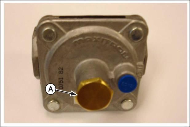
Loosen the large nut (A) in the center of the
regulator. (Figure 1).
Figure 1. Regulator and large Nut.
Read the letters on flat of the needle that is
seated in a small hole on the large nut. You
will see "NAT" (A) or "LP" (B). (Figure 2).
Figure 2. "NAT" and "LP" letters on the needle.
If Liquid Propane is required, push the "NAT"
end of the needle into the small hole on the
large nut. Install the large nut and needle
assembly into the regulator as shown. Tighten
the large nut. (Figure 3).
Figure 3. Installation for Liquid Propane use.
If Natural Gas is required, push the "LP" end
of the needle into the small hole on the large
nut. Install the large nut and needle assembly
into the regulator as shown. Tighten the large
nut. (Figure 4).
Figure 4. Installation for Natural Gas use.
17Trouble Causes and corrective measures
Trouble Causes Corrective measures
Pizza Bottom too Dark Bedplate Thermostat improper setting Decrease bottom temperature
Shorten cook time
Pizza Top too Dark Top Thermostat improper setting Decrease top temperature
Shorten cook time
Pizza Bottom Too Dark and Unbalanced temperature distribution Decrease bottom temperature
Top too Light
Increase Top temperature
Pizza Bottom Too Light and Unbalanced temperature distribution Decrease top temperature
Top Too Dark
Increase bottom temperature
Uneven bakes Improper scaling of dough Scale dough consistently
Dried Out Products Temperature too low Increase temperature
Baking time too long Decrease baking time
Smell of non-burned gas Improper Combustion Inspect that the burning is normal.
Inspect that the gas consumption is not
excessive.
Inspect that the burned gas can flow away
freely.
Inspect for the correct operation of the
aspirator and ventilation of your place.
18Appendix 1 - Parts List
ITEM QTY PART NAME
1 2 Door’s frame
2 2 Door’s glass
3 2 Door’s handle
4 2 Rolling bearing
5 1 Electric motor
6 2 Lamp
7 3 Burner
8 1 Cable gland
9 2 Door’s magnet
10 2 Door’s stop
11 2 Rotated wheel
12 3 Burner’s pilot
13 1 Telescopic sponge mop
19Appendix 2 - Electrical wiring diagram
20You can also read