Comprehensive solution for Hydro Power Stations - Ductile iron pipe for renewable energy PAM commitment for sustainable development - Ductile iron ...

Page created by Lucille Grant
 
CONTINUE READING
Comprehensive solution for Hydro Power Stations - Ductile iron pipe for renewable energy PAM commitment for sustainable development - Ductile iron ...
Comprehensive solution       Ductile iron pipe
for Hydro Power Stations     for renewable
                             energy

                             PAM commitment
                             for sustainable
                             development

Comprehensive pipe systems
Comprehensive solution for Hydro Power Stations - Ductile iron pipe for renewable energy PAM commitment for sustainable development - Ductile iron ...
SUSTAINABLE DEVELOPMENT

                                           Water, fire, iron and energy

                                                                                        QUALITY ASSURANCE AND ENVIRONMENT
                                                                                        ISO 9001
                                                                                        The quality management system introduced by
Hydraulic energy produced by the force of water flowing
                                                                                        PAM has been certified as complying with EN / ISO
downwards inside a pipe is transformed by a turbine                                     9001 by the independent third party (Bureau Veritas
connected to a generator into electricity; this can be rapidly                          Certification). This involves specific internal rules
transported and does not produce any waste or pollution.                                concerning the design, manufacture and sale of
                                                                                        ductile iron products in accordance with high quality
Today, hydroelectricity is still the cheapest form of energy
                                                                                        standards.
in terms of production costs, and ranks high among the
renewable energies.                                                                     A ductile iron pipe
                                                                                        system is a 100%
Compared with traditional fossil fuel power plants, a 1MW
                                                                                        recyclable product.
hydroelectric power station can supply around 630 homes
with electricity and prevents the emission of around 2,500 t
of CO2 into the atmosphere each year.
                                                                                        ISO 14001
Many European countries are investing in hydraulic                                      The PAM’s environmental management system
                                                                                        complies with ISO 14001 Standard
technologies to meet the 20% target set by the European
Union for 2020.

For decades, SAINT-GOBAIN PAM has been a major player
in the development of the hydroelectric sector, supplying
ductile iron mains for penstock pipelines.

Starting from an upstream reservoir, HYDROPAM passes
water to the turbine installed downstream. Depending on
the difference in height and the flow rate, the pipeline can
be subjected to high pressures at the lowest point.

The robustness of ductile iron, combined with its
exceptional resistance to pressure and abrasion, make
HYDROPAM mains the ideal solution, boasting an excellent
service record that goes back over a century.

Available in DN 60 to 2000, built to last and 100% recyclable,
HYDROPAM mains are laid directly in trenches and have a
life cycle that often exceeds a hundred years.

        - 09/09                                                               - 09/09
                                                                          2                                                                     3
Comprehensive solution for Hydro Power Stations - Ductile iron pipe for renewable energy PAM commitment for sustainable development - Ductile iron ...
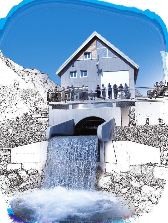
HYDROPAM CONCEPT                                                                                                                        DUCTILE IRON PIPE PERFORMANCES

                                                                                                                                        The properties of ductile iron pipes, fittings and accessories are in conformity with EN 545 Standard.
                                                              1   Inlet valve
                                                              Knife valve with hand wheel.
                                                              Located at the upstream side of the inlet cone.                                                                                Main properties of ductile iron

                                                              2   Inlet cone                                                                                                                  Yield tensile (*), Rp 0.2               300 MPa
                                                              Dynamically designed inlet device with low head loss, partly concreted.
                                                                                                                                                                                              Tensile strength, Rm                    420 MPa
                                                              3   Double flanged pipe                                                                                                                                                 10 % for DN 60 to 1000, 7 % for
                                                              Connected to the inlet cone and concreted into the dam wall.                                                                    Elongation after fracture, A
                                                                                                                                                                                                                                      DN 1100 to 2000

                                                                                                                                                                                              Modulus of elasticity                   1,7 x 10⁵ N/mm3
                                                  2                                                                                                                                           Coefficient                             1,1 x 10⁻² mm/m °C
                                                              3                        5     6                                                                                                Thermal expansion
                                                                                                                                                                                              Density                                 7,05 g/cm3
Upstream Reservoir
                                                                                                                                                                                             (*) 270 MPa when A >= 12 % for DN 40 to 1000 or A >= 10 % for DN > 1000

                                                                                                                                                          Stable mechanical properties over time:
                                              1
                                                                                                                                                      These mechanical characteristics remain constant throughout the service life of the buried pipeline. A
                                                                                                                      7                               high stiffness level makes ductile iron pipe less dependant on the quality of soil embedment.
                                                                          4                                                                           Ductile iron pipes have a high capacity to withstand poor laying conditions.

HYDROPAM concept                                                                                         8
                                                                                                                                                          Impact and point loading:
HYDROPAM is a comprehensive concept which provides a
full set of solutions dedicated to hydraulic power stations                                                                                           Although pipeline laying procedures require avoiding or limiting as much as possible impacts with the
                                                                                                                                                      pipe, zinc coated ductile iron is well known to be the most resistant and suitable for transport over long
 - pipes, fittings, joints and accessories.                                                                                                           distances and for rocky environments.
 - valves, air valves, needle valves.                                                                                                                 This would explain its extensive use in mountainous areas, limestone areas, etc.
 - advice and technical support.                                                                                                        8             Any damage can easily be repaired.

4   EUROSTOP emergency valve                                      7    Ductile iron pipes
A counterweighted butterfly valve installed to prevent            The pipes are supplied in different pressure classes with
damage caused by pipeline failure. This safety device             or without self anchoring joints, depending on the static
works without any external energy supply and shuts                pressure and the slope.
down when the maximum allowable flow rate is excee-                                                                                                                                                                                  Turbine station
ded. The flow rate can be detected by a paddle system
supplied on request.                                              8    Anchoring device
                                                                  Anchor for clamping the pipeline to stable soil.

5   Self-restrained dismantling joint
Dismantling joint for adjustment, easy installation and           9    Needle valve for draining
dismantling.                                                      Safety needle valve used for controlled draining or                                                                                      10
                                                                  synchronous discharge of pipelines under high pressure
                                                                  without cavitation.                                                                                                                                5
6   Automatic air valve (triple function VENTEX)
The air valve ensures safe filling of the pipe and ex-
hausts entrapped air to the atmosphere. The valve pre-            10   EUROSTOP butterfly valve
vents negative pressure in the pipeline when the water            Keeping the valve closed prevents any static pressure
is drained out. A gate valve upstream of the air valve is         building up on the guide blades of the turbine as well as
an option for servicing the air valve, even if a gate valve       any leakage.
is already present in the body.                                                                                                                                                               9

          - 09/09                                                                                                                               - 09/09
                                                                                                                                  4                                                                                                                                     5
Comprehensive solution for Hydro Power Stations - Ductile iron pipe for renewable energy PAM commitment for sustainable development - Ductile iron ...
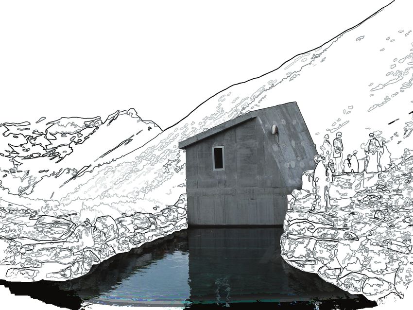
PIPE PROGRAM                                                                                                                          JOINT TECHNOLOGY

PAM offers a complete range of pipe diameters from DN 60 up to DN 2000                                                                                                                       The STANDARD joint has been used for many decades all over the world.
completed by a comprehensive range of fittings and accessories.
                                                                                                                                                                                             Assembly is easy, safe and quick. As the assembly operation needs no welding
See the Pam catalogue “Water mains”.
                                                                                                                                                                                             and coating repair, this push-fit joint is greatly appreciated by contractors
                                   e
                                                                                                                                                                                             when environmental conditions are difficult: winter time, presence of water
            P                                    Lu                                                                                                                                          in the trench bottom, no access for digger, limited time for working, etc.

                                                                                 Ø DE
     Ø DI
ØB

                                                      C30 EN 545                                                                                                                             Ductile iron pipe joints are fully tested in accordance with the requirements of
                                       Natural

                                                                                                                                                                                             EN 545 against positive internal and external pressures, negative pressure, and
                                                                                                                                                                                             cyclic pressure.

Pipes and fittings with STANDARD joint                                                                                                                                STANDARD joint                                                          A self water tighted joint
                 Lu        Angular                    PFA               PFA             PFA          PFA          PFA            PFA
     DN
                 m        deflection                  bar               bar             bar          bar          bar            bar
                                                                                                                                                                                                   1                                                            Contact pressure
      60        6,00          5         c40            64          k9   85    k10       85    k11    100   k12     *     k13       *
      80        6,00          5                        64               85              85           100           *               *
     100        6,00          5                        64               85              85           100           *               *
     125        6,00          5                        64               85              85           100           *               *
     150        6,00          5                        62               79              85           97           100            100
     200        6,00          5                        50               62              71           80           90               99
                                                                                                                                                                                                                                                                Contact pressure
     250        6,00          5                        43               54              61           70           78               86
     300        6,00          5                        40               49              56           63           70               78                                                                                                   Water pressure
     350        6,00          4         c30            35          k9   45    k10       51    *k11   58    *k12   65     *k13      71         STANDARD joint:
     400        6,00          4                        32               42              48           55           61               67         The STANDARD joint is a flexible push-in joint. The seal is provided by radial compression of the EPDM rubber gasket (1). Contact pressure
                                                                                                                                              between gasket and metal increases as the water pressure increases.
     450        6,00          4                        30               40              45           52           57               63
     500        6,00          4                        30               38              44           49           55               60
                                                                                                                                                             UNIVERSAL Ve joint                                                                      Easy anchoring
     600        6,00          4                        30               36              41           46           51               56
     700        6,96          4                         -          k9   34    k10       38    *k11   43    *k12   48     *k13      53                                                    1                2
     800        6,95          4                                         32              36           41           46               50
     900        6,95          4                                         31              35           40           44               48
 1 000          6,96         4*                                         30              34           38           43               47
 1 100          8,19          4                                         29              32           37           41                                                                                     3
 1 200          8,19          4                                         28              32           37           41
 1 400          8,17          3                                         28              31           35           39                                                   5
 1 500          8,16          1                                         27              30
                                                                                                                                                                                               4
 1 600          8,16          3                                         27              30
 1 800          8,15         2,5                                        27              30
                                                                                                                                              UNIVERSAL Ve joint:
 2 000          8,13          2                                         26              29
                                                                                                                                              Leak tightness is ensured by an EPDM rubber gasket (STANDARD joint) (1) in one chamber. The anchoring (axial force transmission) takes
PFA = A
       llowable operating pressure
      please refer to next section «design safety factor» for pressure definitions
                                                                                                                  *= please consult PAM       place through a mechanical arrangement comprising:
                                                                                                                                              - weld bead (5) on the pipe spigot (factory applied), segmented anti-slippage locking rings (3+4), (with a curved external profile )
Pipes are delivered with the following protections systems:                                                                                   - second chamber (2) in pipe socket (with spheroidal internal profile)
                                                                                                                                              - self anchoring function is obtained by confining the locking ring between the external chamber of the socket and the weld bead (5) present
Coating: a layer of metallic zinc ( ZINALIUM for NATURAL pipe range), applied by electric arc spray gun, and covered with a pore                on the spigot of the pipe
sealer layer. High resistance to impact from transport, handling, storage and backfill.
                                                                                                                                              The UNIVERSAL Ve joint combines the advantages of a flexible socket         Ductile iron pipe joints make the laying operations cheaper and easier:
Lining: a layer of cement applied by centrifugal process, (blast furnace cement for potable water or high alumina cement for                  joint and a welded joint:                                                   - simple and fast assembly on site (even when difficult trench or bad
sewage). The mortar is spun at high speed, giving good lining compaction, then cured to optimum mechanical strength.                          - self tightening design: the contact pressure between gasket and metal
                                                                                                                                                                                                                            weather conditions)
The spinning process has the advantage of producing a smooth internal surface layer consisting of very fine particles, giving:                                                                                            - use of standard field equipment on site: crowbar, mechanical winches
                                                                                                                                                increases as the water pressure increases
                                                                                                                                                                                                                            or digger bucket, according to diameter or accessibility in the trench
- Excellent abrasion resistance against raw waters with solid particle content (e.g. sand)                                                    - high resistance to traction stress                                        - flexible joint, suitable for ground movements
- Excellent resistance against mechanical and chemical cleaning operations                                                                    - fully rotational locking system: the UNIVERSAL Ve joint is designed to   - no coating repair after assembly
- Very good resistance to longitudinal bending and ovalisation .                                                                                accept angular deviation even under axial tension: the curved exterior    - no welding operation, no sophisticated equipment
Fields of application are in accordance with EN545 annex D and E.                                                                               of the locking ring (3+4) acts like a pivot on the spheroidal internal    - avoids installation of concrete anchor blocks
PAM can supply special coating for specific applications: please refer to the PAM catalogue                                                     profile of the second chamber (2). Suitable for ground movements            ( for bends, tapers, tees, blank flanges)

                - 09/09                                                                                                                           - 09/09
                                                                                                                                          6                                                                                                                                                          7
Comprehensive solution for Hydro Power Stations - Ductile iron pipe for renewable energy PAM commitment for sustainable development - Ductile iron ...
VALVES PROGRAM                                                                                                                                                                                                VALVES PROGRAM

                                                                                                                                                                                                    E       D

Safety Butterfly valve                                                                                                                                                                                  H
                                                                                                                                                                                                                                                                                       Automatic air valve triple function
                                                                                                                                                                     BUTTERFLY VALVE

                                                                                                                                                                         OLEODYNAMIC ACTUATOR
                                                                                                                                                                         WITH COUNTERWEIGHT
                                                                                                                                                                                                                                                                                                                                           Ventex type DN65-200 PN 10-16-25
DN 150-1600 PN 10-16-25                                                                                                                R

                                                                                                                   A
DN 1800-2000 PN 10-16
High-speed control system types: mechanical-magnetic-ultrasonic
Open-close system types: manual - electrical

                                                                                                                                                                                       DN

                                                                                                                                                                                            F
                                                                                                                   B
                                                                                                                                                                 G

                                                                                                                                           A                                   C
Picture showing mechanical high-speed control and manual oleo dynamic system

Range                                                                                                                                                      E             D
        PFA/PN
DN      10 16         25                                                                                        BUTTERFLY VALVE                                      H
150
200                                                                                                                OLEODYNAMIC ACTUATOR                                                                                                                                                                                                   Filling - emptyng function
                                                                                                                   WITH COUNTERWEIGHT
                                                                                R                                                                                                                                   DN        E       F      H     h1       a        s     Weight                       Air flow intake through large orifice in m3/h        Air vented through large orifice in m3/h
900
                                                                 A

                                                                                                                                                                                                                    65       390     200    258    165     20       15,3    24                          10 000                                                                             10 000
1600                                                                                                                                                                                                                                                                                                     5 000                                                                             5 000
                                                                                                                                                                                                                  80-100     467     244    300    215     20       15,3    40
2000                                                                                                                                                                                                               150       656     405    492    285     24       18,5    115                          1 000                                                                             1 000
                                                                                                                                                                                                                                                                                                           500                                                                             500

                                                                                                                                  DN
For the high-speed control sensor magnetic/induction type or ultrasonic type please contact us                                                                                                                     200       737     448    580    330     29       20,7    170

                                                                                                                                               F
For electrical open-close manipulation please contact us                                                                                                                                                                                                                                                    100                                                                            100
For other pressure types please contact us                                                                                                                                                                      To material types please contact us                                                          50                                                                            50
                                                                 B

                                                                                                                                                                                                                Other pressure or coating types please contact us
                                                                                                                                                                                                                                                                                                              10                                                                           10
    PN 10                                                                                                   G                                                                                                                                                                                                  5                                                                           5

     DN             A              B             C            D                  E A                  F                 CG                  H                   R                  Weight                                                                                                                        1                                                                         1
                                                                                                                                                                                                                                                                                                                       -0.3 -0.25 -0.2 -0.15 -0.1 -0.05 -0.0 0.05 0.1
     150           653            411           446          352               152                  285                210                 111                 667                  190
     200           653            411           446          382               181                  340                230                 141                 667                  203
     250
     300
                   653
                   653
                                  411
                                  411
                                                446
                                                446
                                                             441
                                                             465
                                                                               216
                                                                               240
                                                                                                    400
                                                                                                    455
                                                                                                                       250
                                                                                                                       270
                                                                                                                                           200
                                                                                                                                           224
                                                                                                                                                               667
                                                                                                                                                               667
                                                                                                                                                                                    226
                                                                                                                                                                                    246                                                                                                      Self-restrained dismantling joint
     350           757            467           533          544               259                  505                290                 208                 777                  382
     400           757            467           533          595               330                  565                310                 259                 777                  416                                                                                                                                                                     DN40-2000 PN 10-25
     450           991            604           548          657               354                  615                330                 316                 1020                 604
     500           991            604           548          682               379                  670                350                 341                 1020                 632
     600          1272            788           772          722               433                  780                390                 446                 1304                 899
     700          1272            788           772          813               504                  895                430                 537                 1304                 1054                          PN 10                                         Tie Bars
     800          1520            939           809          926               596                  1015               470                 585                 1560                 1672
                                                                                                                                                                                                                   DN         A      ØD    Ø D1    ØK      N         M      L       Weight    +e   -e
     900          1520            939           809          975               642                  1115               510                 634                 1560                 1868
                                                                                                                                                                                                                    40       200     150    49     110     4        M16    330        11      30   30
    1000          1768           1090           979          1151              712                  1230               550                 710                 1815                 2987
                                                                                                                                                                                                                    50       200     165    61     125     4        M16    330        13      30   30
    1200          1768           1090           979          1162              850                  1455               630                 721                 1815                 3428
                                                                                                                                                                                                                    60       200     175    76     135     4        M16    330        14      30   30
    1400          1982           1208          1163          1359              962                  1675               710                 768                 2040                 5042
                                                                                                                                                                                                                    65       200     185    77     145     4        M16    330        15      30   30
    1500          1982           1208          1163          1410              1013                 1785               750                 819                 2040                 5403
                                                                                                                                                                                                                    80       200     200    90     160     8        M16    330        21      30   30
    1600          1982           1208          1163          1462              1065                 1915               790                 871                 2040                 6000
                                                                                                                                                                                                                   100       200     220   116     180     8        M16    330        22      30   30
    1800          2196           1326          1459          1796              1250                 2115               870                 915                 2265                 9318                                                                                                                                               For other material types please contact us
                                                                                                                                                                                                                   125       200     250   142     210     8        M16    330        28      30   30
    2000          2196           1326          1459          1891              1345                 2325               950                 1110                2265                10723                                                                                                                                         For other pressures or coating types please contact us
                                                                                                                                                                                                                   150       200     285   171     240     8        M20    330        37      30   30
                                                                                                                                                                                                                                                                                                                                         For DN 700 to 2000, please contact us
                                                                                                                                                                                                                   200       280     340   222     295     8        M20    430        53      40   40
Needle valve for synchronous discharge                                                                                                                                                                             250       280     395   276     350     12       M20    430        72      40   40                                                   L
                                                                                                                                                                         420        706.5                          300       280     445   328     400     12       M20    430        81      40   40                                                   A
DN 100-900 PN 10-16-25                                                                                                                                                                                             350       280     505   360     460     16       M20    430       109      40   40
DN 1000 PN 10-16                                                                                                                                 OPENING                                                           400       280     565   411     515     16       M24    450       150      40   40
                                                                                                                                                                                                                   450       330     615   462     565     20       M24    530       180      50   50
                                                                                                   1050

                                                                                                                                                                                                                                                                                                             N tie bars on ø k
                                                                                                                                                                                                                   500       330     670   514     620     20       M24    530       206      50   50
                                                                                                                                       R1304                                                                       600       330     780   617     725     20       M27    550       264      50   50
                                                                                                                                                           432
                                                                                    DN600

                                                                                            FLOW
                                                                                                                                                                                                                Dimensions in mm                                                 Wheight in Kg
                                                                                                                                                           432

                                                                                                                                                                             ø840

                                                                                                     327             1200                  474
                                                                                                           N°20 HOLES ø36 - DIAMETER OF BOLTS CIRCLE 770
            - 09/09                                                                                                                                                                                                        - 09/09
For dimensions and weight, please consult us                                                                           ex : DN 600 PN 16
                                                                                                                                                                                                8                                                                                                                                                                                                       9
Comprehensive solution for Hydro Power Stations - Ductile iron pipe for renewable energy PAM commitment for sustainable development - Ductile iron ...
PAM SERVICES                                                                                                                  PAM SERVICES

PAM’s technical teams are ready to assist the client at any stage of the project, from information on our ductile               Steep inclines
iron products and their use through to technical assistance at the beginning of pipe laying.
                                                                                                                              Beyond a certain angle, the friction between a pipeline and the ground is insufficient to hold the pipeline in
PAM experts can support customers, consultants and contractors for:                                                           position: a buried main needs to be anchored when the incline exceeds an angle dependent on pipe dimension,
                                                                                                                              soil characteristics and laying conditions. The longitudinal gravitational movement then has to be counteracted
  - Soil survey analysis and corrosion protection                                                                             by the use of concrete anchor blocks for each pipe, or better, by the use of anchored joints or by a combination
  - Hydraulic design and buried pipe engineering                                                                              of both techniques.
  - Pipe system designing
  - Laying operations
  - Logistic arrangements (transportation by ship, truck, storage, etc.)

PAM is also represented by local distributors that can propose equipment and immediate services during pipeline
installation (pipe cutting, on-site logistics arrangements, after sales services, etc.)

   Design Safety Factor                                                                                                                                                                                                             2
Long term safety of buried pipelines will be achieved if, at the design
stage, it is possible to know with a fair degree of confidence:

  - the properties of the pipe material and of the pipe itself, as laid
    down in the standards and guaranteed by the manufacturer;
                                                                                                                              In addition, a section of self-        The maximal axial force is             The main should be laid downhill
  - the loads which the pipeline will be subjected to, as determined                                                         anchored pipes should be anchored      supported by the first self-anchored   starting from the highest point, so
    by adequate design methods.                                                                                               either by an anchor block situated     joint below the block. This force is   that the self-anchoring system is
                                                                                                                              behind the socket of the leading       a function of the gradient and the     fully engaged and tensioned.
• Resistance against pressure:                                                                                                pipe 1 or by an additional self-       length of the anchored section. The
  Ductile iron Pipes are designed to withstand pressure according EN545 STANDARD annex A:                                     anchored length (L) installed in the   maximum permissible length is
                                                                                                                              flat section behind the uppermost      therefore defined by the strength
  PFA = calculated with the minimum tensile strength divised by 3 (safety factor 3)                                           bend 2 .                               limit of the self-anchored joint.
  PMA = 1,2 PFA
  PEA = PMA+ 5 bar

Where:
                                                                                                                              Please contact the technical department of PAM or refer to PAM tools.
  - PFA = (Allowable operating pressure) internal pressure, excluding water hammer, that a component can safely
    and continuously withstand under permanent hydraulic service
  - PMA = (Allowable maximum operating pressure) maximum internal pressure, including water hammer, that a
    component can safely withstand during service
  - PEA = (Allowable test pressure) maximum hydrostatic pressure that can be applied onsite to a newly laid component.

• Resistance against earth loads:                                          Minimun Stiffness for ductile iron pipe
                                                                                        EN545 K9
S = Typical stiffness for ductile iron pipes are set out in EN545
standard, Annex C, Table C.1. They clearly explain why the                   DN                 S
laying conditions are not so critical for ductile iron pipes com-            400                72 000 N/m2
pared to other materials.                                                    800                30 000 N/m2
                                                                             1200               20 000 N/m2
                                                                             2000               16 000 N/m2

      - 09/09                                                                                                                       - 09/09
                                                                                                                         10                                                                                                                       11
Comprehensive solution for Hydro Power Stations - Ductile iron pipe for renewable energy PAM commitment for sustainable development - Ductile iron ...
PAM SERVICES                                                                                                                        PAM LIBRARY AND SOFTWARE TOOLS

   Hydraulic flow capacity                                                                                                          PAM proposes a selection of documentation and software for the attention of consultants
                                                                                                                                    and contractors:
The equivalent surface roughness, k, of a pipeline depends not only on pipe wall smoothness, but also and more
importantly on the number of bends, tees and branches, pipeline profile irregularities, and the development of                       Library
internal bio film.

                                                                                                                                                   A 450-page ”User’s Guide” or CD ROM providing clear information
Experience has shown that k=0.1 mm is a reasonable value (whatever the internal lining) for distribution mains,                                    and detailed application procedures for PAM products.
and slightly less (0.06 to 0.08 mm) for large mains with a small number of fittings per kilometre.

Any comparison of flow capacity of pipe material based on a different roughness coefficient would be a very
theoretical speculation.                                                                                                                                            A series of teaching and operational instruction sheets
                                                                                                                                                                                                          to be used on site

       The reason is the following; head loss is the sum of 3 effects:

       a) Water friction to itself (linked to the water viscosity = 2.51/Re l 1/2)
       b) Water friction on the pipe wall (linked to the roughness = k / 3.71 D)
                                                                                                                                                   “Self-anchoring solutions for ductile iron pipes”: a comprehensive guide
       c) Local changes to flow (bend, joints, etc)                                                                                                to explain the concept of anchor joints and the different existing technologies.

Internal water friction (term a) is the main part of the head loss. Water friction on the pipe wall (term b), depending only
on material roughness, is much less (evaluated at 7% max of term a for a cement-lined ductile iron pipe).

                                                                                                                                                                                       A full experienced, coherent and recognised
                                                                                                                                                                                                 European Standard System, EN545
The actual internal diameter of the pipe is the most important parameter: for a given flow rate, each 1% less in
diameter is 5 % more head loss, and for a given head loss (gravity main) each 1% less in diameter is 2.5 % less in
the resultant flow rate                                                                                                              Software

Therefore, special attention has to be paid to the influence of the hydraulic internal diameter of the pipe.                                              PAMCAD: design and dimensioning software to make the work of desi-
                                                                                                                                                          gners and consultants easier, providing the range of PAM product
                                                                                                                                                          software for dimensioning of:
PAM uses software to evaluate the different cases. Please contact PAM.                                                                                    - butterfly safety valves
                                                                                                                                                          - needle valves
                                                                                                                                                          - air valves

                                                                                                                                      PAMKIT: design software to design standardized solution for air release, drainage
                                                                                                                                      and shutoff, and to provide logistic benefits. Reference shall also be made to the
                                                                                                                                      relevant national regulations and standards when applicable.

                                                                                                                                                                       PAMTC: assistance using in-house calculations tools dedicated to :
                                                                                                                                                                       - Pipe laying in steep incline
                                                                                                                                                                       - Dimensionning concrete blocks
                                                                                                                                                                       - Dimensionning self-anchored length
                                                                                                                                                                       - simulating Head losses

                                                                                                                                     Reference shall also be made to the relevant national regulations and standards when available.

      - 09/09                                                                                                                            - 09/09
                                                                                                                               12                                                                                                           13
Comprehensive solution for Hydro Power Stations - Ductile iron pipe for renewable energy PAM commitment for sustainable development - Ductile iron ...
PAM SERVICES                                         REFERENCES

                                                             Every year, over 100 projects are manufactured
                                                    by SAINT-GOBAIN PAM for hydraulic power stations and delivered
Comprehensive solution     Ductile iron pipe                            in Europe and worldwide.
for Hydro Power Stations   for renewable
                           energy

                           PAM commitment
                           for sustainable
                           development

    - 09/09                                             - 09/09
                                               14                                                                    15
Comprehensive solution for Hydro Power Stations - Ductile iron pipe for renewable energy PAM commitment for sustainable development - Ductile iron ...
SAINT-GOBAIN PAM worldwide
 ALGERIA                                          COLOMBIA                                              INDIA                                                 PORTUGAL
 SAINT-GOBAIN PAM ALGERIE                         SAINT-GOBAIN PAM COLOMBIA                             SAINT-GOBAIN PAM                                      SAINT-GOBAIN PAM PORTUGAL
 Z.I. Sidi Abdelkader-Ben Boulaid - BP 538        Terminal terrestre de carga de Bogota                 Grindwell Norton Ltd                                  Est. Nac. 10 - Lugar de D. Pedro -Apartado 1708
 09000 - BLIDA - Algeria                          Etapa 1, Bodega 9, Modulo 3                           5th Level, Leela Business Park - Andheri-Kurla Road   P-2690-901 - SANTA IRIA DE AZOIA - Portugal
 Phone: + 213 (0) 25 36 00 60                     Km 3,5 costado sur autopista - Medellin               MUMBAI - 400059 - India                               Phone: + 351 218 925 000
                                                  COTA CUNDINAMARCA - Colombia                          Phone: + 91 22 402 12 121
 ARGENTINA                                        Phone: + 57 (1) 841 5832                                                                                    ROMANIA
 SAINT-GOBAIN PAM ARGENTINA                                                                             ITALY                                                 SAINT-GOBAIN CONSTRUCTION PRODUCTS
 Bouchard y Enz                                   CZECH REPUBLIC                                        SAINT-GOBAIN PAM ITALIA SPA                           ROMANIA S.R.L. - PAM Business Unit
 1836 - LLAVALLOL - BUENOS AIRES - Argentina      SAINT-GOBAIN PAM CZ s.r.o.                            Via Romagnoli n°6                                     Str. Tipografilor nr. 11-15
 Phone: + 54 11 42 98 9600                        Po ernická 272/96                                     I-20146 - MILAN - Italy                               S-Park/Corp - B3 B4 - Sector 1 - Cod 013714
                                                  108 03 Praha 10 - Czech Republic                      Phone: + 39 02 42 431                                 BUCHAREST - Romania
 AUSTRALIA                                        Phone: + 296 411 746                                                                                        Phone: + 40 21 207 57 37
 SAINT-GOBAIN PAM                                                                                       JORDAN
 15 Edgars Road                                   FINLAND                                               SAINT-GOBAIN PAM REGIONAL OFFICE                      SLOVAKIA
 THOMASTOWN VIC 3074 - Australia                  SAINT-GOBAIN PIPE SYSTEMS OY                          Abu Zaid Center - Office # 8                          SAINT-GOBAIN CONSTRUCTION PRODUCTS
 Phone: + 61 (0) 3 9358 6122                      Nuijamiestentie 3A                                    35 Saad Bin Abi Waqqas St, - PO BOX 831000            PAM Business Unit
                                                  FIN-00400 - HELSINKI - Finland                        11183 AMMAN - Jordan                                  Stara Vajnorska 139
 AUSTRIA                                          Phone: + 358 207 424 600                              Phone: + 962 6 551 4438                               83102 - BRATISLAVA- Slovakia
 SAINT-GOBAIN GUSSROHRVERTRIEB                                                                                                                                Phone: + 421 265 45 69 61
 ÖSTERREICH GmbH                                  FRANCE & DOM-TOM                                      MOROCCO
 Archenweg, 52                                    SAINT-GOBAIN PAM (HEAD OFFICE)                        SAINT-GOBAIN MAROC DEVELOPMENT                        SOUTH AFRICA
 A-6020 - INNSBRUCK - Austria                     91 Avenue de la Libération                            2 allée des Figuiers - Aïn Sebaâ                      SAINT-GOBAIN CONSTRUCTION PRODUCTS
 Phone: + 43 512 341 717-0                        54076 NANCY CEDEX - France                            CASABLANCA - Morocco                                  PAM Business Unit
                                                  Phone: +33 3 83 95 20 00                              Phone: + 212 522 66 57 31                             N1 Business Park
 BELGIUM                                                                                                                                                      Corner Olievenhoutbosch Road & Old Johannesburg Road
 SAINT-GOBAIN PIPE SYSTEMS                        SAINT-GOBAIN PAM                                      MEXICO                                                Samrand - PO BOX 700
 Raatshovenstraat, n°2                            (France Commercial Department)                        SAINT-GOBAIN PAM MEXICO                               GERMISTON - South Africa 1400
 B-3400 - LANDEN - Belgium                        CRD – Chemin de Blénod – B.P. 109                     HORACIO 1855-502 - Colonia Los Morales - Polanco      Phone: +27 12 657 2800
 Phone: + 32 11 88 01 20                          54704 PONT A MOUSSON CEDEX - France                   11510 - MEXICO D.F. - Mexico
                                                  Phone: +33 3 83 80 73 00                              Phone: + 52 55 5279 1657                              SPAIN
 BRAZIL                                                                                                                                                       SAINT-GOBAIN PAM ESPANA SA
 SAINT-GOBAIN CANALIZACAO LTDA                    SAINT-GOBAIN PAM
                                                                                                        NETHERLANDS                                           Paseo de la Castellana n°77 - Edificio Ederra - Planta 10
 Praia de Botafogo 440 7° andar                   (Europe and International Commercial Departments)                                                           E-28046 - MADRID - Spain
                                                                                                        SAINT-GOBAIN PIPE SYSTEMS
 22250-040 - RIO DE JANEIRO - RJ - Brazil         21 avenue Camille Cavallier                                                                                 Phone: + 34 91 397 20 00
                                                                                                        Markerkant 10-17
 Phone: + 55 21 2128 1677                         54705 - PONT A MOUSSON CEDEX - France
                                                                                                        1316 - AB ALMERE - Nederland
                                                  Phone: + 33 3 83 80 67 89                                                                                   UNITED ARAB EMIRATES
                                                                                                        Phone: + 31 36 53 333 44
 CHILE                                                                                                                                                        SAINT-GOBAIN PAM
                                                  SAINT-GOBAIN PAM
 SAINT-GOBAIN PAM CHILE                                                                                 NORWAY                                                PO BOX 47102 - Building N° 1092 - Villa N° 7
                                                  (Local Agency of The Antilles)
 Antillanca Norte 600                                                                                   SAINT-GOBAIN PAM NORWAY                               Muroor Road - ABU DHABI - United Arab Emirates
                                                  Rue Alfred Lumière - ZI de Jarry - BP 2104
 Parque Industrial Vespucio, Comuna de Pudahuel                                                         Brobekkveien 84                                       Phone: + 971 2 448 20 10
                                                  97122 - BAIE MAHAULT - Guadeloupe
 SANTIAGO DE CHILE - Chile                                                                              N-0614 OSLO - Norway
                                                  Phone: + 33 590 26 71 46
 Phone: + 562 444 13 00                                                                                 Phone: + 47 23 17 58 60                               UNITED KINGDOM
                                                                                                                                                              SAINT-GOBAIN PAM UK
 CHINA                                            GERMANY                                               PERU                                                  Lows Lane - Stanton-by-Dale
 SAINT-GOBAIN PAM CHINA (SHANGAI)                 SAINT-GOBAIN PAM DEUTSCHLAND                          SAINT-GOBAIN PAM PERU                                 ILLKESTON - DERBYSHIRE - DE7 4QU
 1812 Ocean Tower                                 Saarbrucker Strasse 51                                Avenida de los Faisanes N° 157 - Chorillos            United Kingdom
 550 Yan'An East Road - SHANGAI 200001 - China    66130 - SAARBRUCKEN - Germany                         LIMA 09 - Peru                                        Phone: + 44 115 930 5000
 Phone: + 86 21 6361 2165                         Phone: + 49 681 87 010                                Phone: + 511 252 40 34/35
                                                                                                                                                              VIETNAM
 SAINT-GOBAIN PAM CHINA (XUZHOU)                  GREECE                                                POLAND                                                SAINT-GOBAIN PAM
 Dong Jiao Yangzhuang                             SAINT-GOBAIN SOLINOURGEIA                             SAINT-GOBAIN CONSTRUCTION PRODUCTS POLSKA             201-203 Cach Mang Thang 8, Ward 4 - District 3
 PC 221004 - XUZHOU - Jiangsu Province - China    5 Klissouras Str.                                     SP Z.O.O - PAM Business Unit                          HO CHI MINH CITY - Vietnam
 Phone: + 86 516 8787 8107                        GR 14482 - METAMORFOSI - ATHENS - Greece              UI. Cybernetyki 21                                    Phone: +84 8 39 30 72 74
                                                  Phone: + 30 210 28 31 804                             PL-02-677 WARSZAWA - Poland
 SAINT-GOBAIN PAM CHINA (MAANSHAN)
                                                                                                        Phone: + 48 22 751 41 72
 Hua Gong Road Cihu
 PC 243052 - MAANSHAN Anhui Province - China      HONG KONG
 Phone: + 86 555 350 8040                         SAINT-GOBAIN PIPELINES
                                                  H15/F Hermes Commercial Centre - 4-4A Hillwood Road
                                                  TSIM SHA TSUI - KOWLOON - Hong Kong
                                                  Phone: + 852 27 35 78 26

www.pamline.com
SAINT-GOBAIN PAM
Head office
91, avenue de la Libération
54076 NANCY CEDEX
FRANCE

Marketing Department –
Water & Sewage
21, avenue Camille Cavallier
54705 PONT-A-MOUSSON CEDEX
FRANCE
Phone: +33 (0)3 83 80 73 50
Comprehensive solution for Hydro Power Stations - Ductile iron pipe for renewable energy PAM commitment for sustainable development - Ductile iron ...
You can also read