Agility Telemetry Radio (ATR) User Manual - Oct 2012 Revision D.2
←
→
Page content transcription
If your browser does not render page correctly, please read the page content below
Agility Telemetry Radio (ATR)
        User Manual

            Oct 2012

           Revision D.2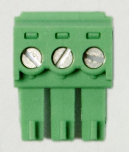
Quick Start Procedure

Note: Prior to starting the installation process, go to the KTS Wireless website
(ktswireless.com) and download a copy of the ATR Element Management System (EMS)
software. Store this software on your PCs Desktop.

Follow the steps below to install and configure Agility Telemetry Radio (ATR):

   1. Select the location for the ATR. Must be an area free of water intrusion with a
      temperature range of -30 to +60 deg C (-22 to 140 deg F). It is always best to use the
      mounting option shown in Figure 1 below to provide good ‘heat sinking’ of the ATR case
      to a large metal surface or DIN rail. This will reduce the operating temperature of the
      ATR and surrounding equipment within the same enclosure.

                           Figure 1: ATR Optional Mounting Bracket

       See the KTS website for ordering information. Correct mounting is critical to maximizing
       ATR performance and reliability.

   2. Locate the coaxial cable to the antenna. This should be a good quality, low-loss cable
      that is as short as possible. This cable should include an in-line surge arrestor to prevent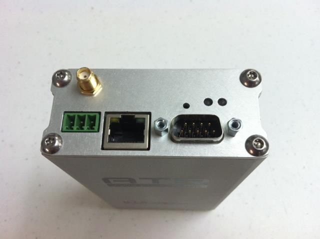
lightning strike damage to the radio. The cable should have a BNC (F) connector or an
       adapter will be needed. See the KTS Wireless website for ordering information, if one is
       needed.

   3. Locate the power source. The ATR requires a 9-24 VDC input and draws about 2.5 A (at
      12 VDC) when transmitting. Power is supplied via the Green Terminal Block at the end
      of the unit (See Figure 2). The mating terminal block connector is supplied with the ATR
      and can be used to connect to an existing power supply. Alternately, a separate power
      supply (12 or 24 VDC) can be purchased directly from a OEM supplier provided it meets
      the FCC or other regulatory requirements when powering the ATR.

                                                      Power/Fan (TB)

                                                   Antenna (SMA)
                                                   Ethernet (RJ45)

                                                      Serial Data (DB9)

                                  Figure 2: ATR Connections

The proper wiring for the Terminal Block (TB) is shown in Figure 3 below: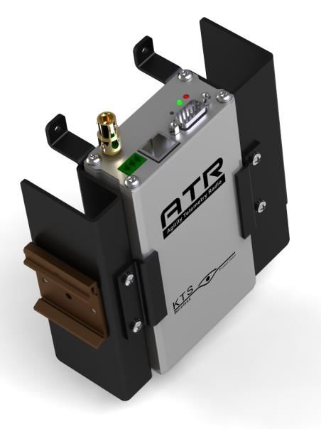
Ground
                                           +12 or 24 VDC In (External Fan)

                                            +12 to 24 VDC In (Radio)

                    1    2     3

                               Figure 3: ATR Power Connections

Note that the radio is powered using pins 1 and 3 and accepts any voltage from 12 to 24 VDC.
Pins 2 and 3 can be used to connect to an external fan near the radio if additional cooling is
required. A thermostat inside the ATR will turn the fan on and off based on its internal
temperature. The maximum current supported (internal fuse) for the fan is 0.75 A at 12 VDC.

   4. Once the power is supplied to the ATR, observe that the green power LED is illuminated.
      It takes about 7-10 seconds for the ATR to boot-up. After this, only the green power LED
      should be on. Figure 4 summarizes the LEDs and their meaning.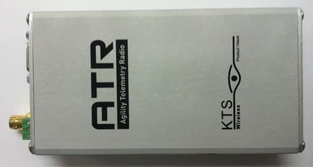
Reset Button (Recessed)
                                                               (Depress for 12 secs for
                                                               Factory Defaults)
                  LAN Speed
                                                               Power on (GRN) or
             (GRN = 10 Mb/s
                                                               Summary Fault (RED)
             Off = 100 Mb/s)
                                                                Wireless Link Activity
            Ethernet Activity                                   (Amber = TX; Grn = RX)
             (Flashes Yellow)

                                Figure 4: ATR LEDs and definitions

5. Connect a laptop to the ATR as shown in the Figure 5. Double-click on the icon below to
   start the EMS software.

                                       EMS_2.3.23.6.jar

              Element Management
              System (EMS) Software                       Agility Telemetry
                                                            Radio (ATR)

                                        Ethernet cable
                      Laptop

                            Figure 5: EMS to ATR Connection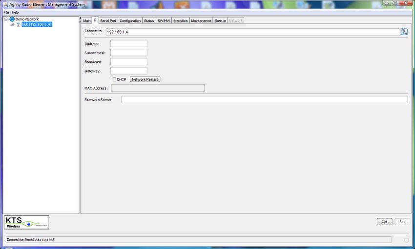
6. The Main screen will appear (See Figure 6). Enter a valid password and click on Login.
   The IP Tab will open if a valid password is entered. Contact KTS Wireless to obtain your
   password. Section 4.0 of this manual contains the details of using the ATR Element
   Management System (EMS). Jump to Section 4.0 for details on setting up the EMS and
   resetting the ATR IP addresses (i.e., changing from the default value).

7. The default IP address of the ATR is 192.168.1.4. This address is automatically loaded
   in the Connect to field at the top. Click on the GET button at the bottom if this default
   address is still loaded in the ATR and not been changed. Note: Pressing and holding
   the recessed Reset button (See Figure 4) for at least 12 seconds will force the radio
   back to its default settings. The default radio IP address is 192.168.1.4.

   If the ATR’s IP address is unknown, clicking on the ‘magnifying glass’ icon to the right of
   the ‘connect to’ will initiate a search. If it is discovered in the search, a pop-up window
   will appear with the unit’s serial number and IP address.

8. Open the Configuration Tab. Select the Link Configuration (channel bandwidth) from
   the pull-down menu. Enter the desired Frequency in Hz (with or without commas
   separators). Make sure the desired frequency is supported by the RF Card installed in
   the ATR. The following ranges are supported:

                  RF Card Band             Frequency Range (MHz)

                       VHF                 145.0 to 225.0 (Band 15 or 26)

                       UHF                 450.0 to 470.0 (Band 28)

   The ATR configuration printed label (on the bottom side) indicates the RF Band
   supported (VHF or UHF). Verification of the Radio band can be found on the SW/HW
   tab (RF Band is displayed in the upper right of the tab).

9. Set the Transmit Power level. Valid entries are 10 to 37 (dBm).

10. Enter the Radio Type (Remote or Hub). All networks require a single hub. This Hub
   radio controls the Media Access Control (MAC) software and implements a round-robin
   polling of all remote sites that have ‘joined’ the network. All remote sites automatically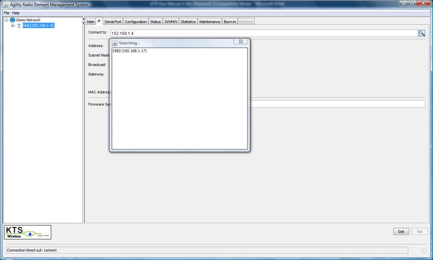
join the Hub/network if they are configured with the same frequency and link
configuration as the hub and have sufficient signal strength to communicate with it.
11. Enter the Site Name (optional). This is a convenient name for the location or site and
can be used by operation staff for identification. Its value does not affect radio
operation. Up to 15 characters can be entered. This name is used by the optional
Network Performance Software (NPM) to display the status of sites and send alerts. It is
recommended that a unique name be given to each site.
12. Click on SET to make the desired Configuration changes within the ATR. The ATR will
automatically reset and begin using the new configuration information. Allow about 7-
10 seconds for this process to complete. And then press the Get button to verify the
new information is stored within the ATR. This information will be saved permanently
within the ATR until changed in the future and will not be lost if the ATR looses power.
13. If the serial port is used, open the Serial Port tab. Select the desired baud rate from the
pull down menu (1200 to 38400 bits per second). This value should normally be less
than the over-the-air data rate indicated in the Link Configuration field. Select the
desired character length, parity and number of Stop bits from the pull-down menus.
The receive (from user device) and transmit (from the ATR) data can also be inverted by
the ATR by checking the associated Data Invert boxes.
14. The serial port uses a transparent mode of operation and operates as follows:
When user data is detected on the serial port, the ATR collects all bits
received into a packet of up to M bytes (configurable max packet size).
Multiple packets may be required to capture the entire message, if longer
than the configured max size.
When the port goes idle for N (configurable) character times, the packet
is transmitted over the wireless link
This feature allows the ATR to be transparent to the serial port protocol and uses data
port activity to determine when to transmit. This mode will support most serial port
SCADA protocols
15. Click on SET to make the desired Serial Port changes within the Radio.
16. The ATR should now be configured and ready for installation and operation.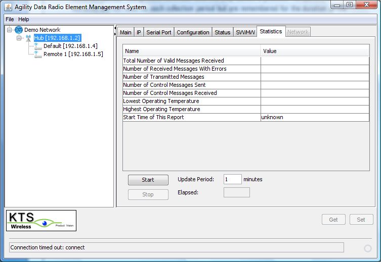
Figure 6: ATR EMS Login Screen
Contents

1.0 Product Description ........................................................ 11

2.0 Applications.................................................................... 14

3.0 Specifications ................................................................. 17

4.0 ATR Element Management System ................................. 19

5.0 Upgrading Software ........................................................ 33
Copyright Notice

Copyright 2012, KTS Wireless, Inc, All rights reserved

Operational and Safety Notices

RF Exposure
The radio described in this manual transmits RF energy. The concentrated energy from the
antenna may pose a health hazard. All antennas used with this radio must be installed to
provide a minimum separation from all persons of 100 cm (40 inches). The above separation
distance must be maintained at all times. More information can be obtained from the FCC at
the following website:

http://www.fcc.gov/Bureaus/Engineering_Technology/Documents/bulletins/oet65/oet65.pdf

FCC Part 15 Notice
The transceiver complies with Part 15 of the FCC Rules. Operation is subject to the following
two conditions: (1) this device may not cause harmful interference, and (2) this device must
accept any interference received, including interference that may cause undesired operation.
This device is specifically designed to be used under Section 15.247 of the FCC Rules and
Regulations.

Any unauthorized modification or changes to this device without the express approval of
KTS Wireless may void the user’s authority to operate this device. Furthermore, this device is
intended to be used only when installed in accordance with the instructions outlined in this
manual. Failure to comply with these instructions may also void the user’s authority to
operate this device.
1.0 Product Description

The Agility Telemetry Radio (ATR) shown in Figure 1.1 below is designed to provide a reliable
wireless connection for digital communication in the following frequency bands:

                             145 to 225 MHz (VHF – Band 15 or 26)

                             450 to 470 MHz (UHF – Band 28)

                           Figure 1.1: Agility Telemetry Radio (ATR)

The ATR is configured to operate in these bands only and limit its maximum transmit power to
levels outlined in Part 90 of the FCC rules and regulations. The modem functionality is
comprised of software which is loaded at the time of manufacturing. It can be upgraded in the
future to add additional features.
The unit is housed in an aluminum enclosure which is not weather-tight. Two printed circuit
boards are included: RF and Digital. The RF board is provided in one of three configurations as
outlined in Table 1 below:
RF Band Frequency Range Max Transmit Power
VHF 150.0 to 174.0 MHz 4.6 W
VHF 217.0 to 220.0 MHz 2W
UHF 450.0 to 470.0 MHz 3.3 W
Table 1: Frequencies and Transmit Power Levels
Note: While the ATR can transmit up to 5 W, it is currently only approved for the power
levels above when used in the USA under FCC regulations (Part 90).
These RF cards all provide a common differential baseband I/Q interface to the Digital board.
The RF board includes transmit, receive, synthesizer and control sections. The transmit section
includes an Intermediate Power Amplifier (IPA), Power Amplifier (PA), Variable Attenuator and
Forward and Reverse Power Detectors. The PA provides up to 5 Watts (37 dBm) of RF output
power at the ATR antenna connector. The Variable Attenuator is used by the Control system
processor to set and maintain the transmitted RF power level. A closed-loop process is used
with the Forward Power Detector to maintain the desired output level under all conditions.
The Reverse Power Detector is used to detect impedance mismatches which may occur with an
antenna or cable failure and will automatically shut the PA down if high reflected power is
detected.
The receive section of the RF board includes a Tunable Bandpass Filter (TBPF), Low Noise
Amplifier (LNA) and Variable Attenuator. The TBPF is centered by the control processor about
the radio’s operating frequency and has a 20 MHz passband. The LNA provides gain and a noise
figure of about 4 dB.
The synthesizer section includes a 20 MHz Frequency Reference which is a Temperature-
Compensated Crystal Oscillator (TCXO) with Stratum 3 frequency stability. This reference is
multiplied up to the desired operating frequency within the Synthesizer. The output is appliedto the Digital Up and Downconverters. This provides direct modulation and demodulation of
the baseband, modulated signal.
The control section includes a processor with on-board memory, analog to digital converters
and general purpose I/O. It also includes a serial port which is used to communicate with the
processor on the Digital board. The processor manages the transmit power and programs the
synthesizer to tune to the desired operating frequency. The memory contains the processor
software along with critical calibration tables which are generated during manufacturing. These
tables provide accurate transmit power setting across the band, receive power estimation (+ 3
dB) and tunable filter control.
The Digital board provides the user ports, message routing and radio management functions.
The radio provides an RS-232 serial and an Ethernet port for connection to user devices. The
pin-out for the serial port is shown in Table 2 below.
Pin Function
2 Transmit Data (from user)
3 Receive Data (to user)
5,6 Ground
7 Clear to Send (CTS)
8 Request to Send (RTS)
1,4,9 Not Used
Table 2: DB9 Signals for RS232 Serial Port2.0 Applications
The most common application for the ATR is a ‘star’ network where a single hub site
communicates to a collection or remote sites as shown in Figure 2.1.
Remote Remote
Radios Radios
Hub
Radio
Server Router
Figure 2.1: Star Network Configuration
The Hub ATR is typically connected to an omnidirectional antenna via a length of coaxial cable.
The signal transmitted by the Hub ATR is then transmitted in a 360-degree pattern to all remote
sites within a range supported by the configured transmitted power. Each remote site ATR is
typically connected to a directional antenna via a length of coaxial cable. These antennas are
‘pointed’ toward the Hub to achieve maximum gain.
User devices are connected to the serial port or Ethernet connectors of the ATR. The point-to-
multipoint network shown in Figure 2.1 interconnects the Hub ATR with all remote ATRs over
the air. Media Access Control (MAC) software within the ATR allows all the radios to share the
wireless spectrum on a non-interfering basis.The Hub ATR automatically performs the polling of all remote ATRs. This happens
automatically and transparently to the user devices. This MAC is referred to as Poll/Select.
When a remote ATR receives an IP message over the Ethernet port it is routed through a
Learning Bridge in the ATR. If this bridge determines it should be transmitted over the air, the
ATR buffers the message until the next poll is received from the Hub ATR and transmits the
message. Serial messages received are collected into a packet of up to the maximum message
size (configured by user) and transmitted after the next Hub poll. Messages smaller than this
configured maximum may be sent if activity on the serial port data line is idle for up to the
configured maximum idle character time (in characters). The most efficient serial port
configuration occurs when the maximum message forwarding size is slightly higher than the
max message size on the serial port and when the maximum idle character time configured is
slightly longer than any, normal inter-character delay on the serial port. This configuration
ensures that serial port packets are sent in a single transmission over the air.
User data transmitted from the Hub can be routed from the Ethernet port to all serial ports at
the remotes. This feature allows both user ports (serial and Ethernet) to be used
simultaneously at remotes. A UDP connection to the hub radio over the Ethernet port can be
established using port 3123 (i.e., 192.168.1.4:3123). The payload portion of these UDP packets
will be sent over the air to all remote sites in the network and forwarded to the serial port for
delivery to the attached serial devices. These devices must determine which of these broadcast
messages are for the individual device based on internal addressing. Other Ethernet traffic (not
sent to port 3123) is routed normally through the learning bridge and, if required, sent over the
air to all remotes. Each remote routes these messages to locally attached devices based on
their learning bridge forwarding tables.
Link Configurations (LCs)
Currently the ATR supports 6.25, 12.5, 25 and 50 kHz channel bandwidths using shaped, 2-FSK
modulation. The over-the-air data rates for these channel sizes are shown below:
Data Rate (kb/s) Channel Bandwidth (kHz)
4.8 6.25
9.6 12.5
19.0 25.0
38.0 50.0Since the throughput on these wireless links is limited by the relatively narrow channel bandwidths, it is strongly recommended that IP routers are used between the ATR and local LANs.
3.0 Specifications

Electrical

Typical Licensed Frequency bands

         VHF (Band 26)             150 to 174 MHz

         VHF (Band 15)             217 to 220 MHz

         UHF (Band 28)             450 to 470 MHz

RF Transmit Power                  10 to 37 dBm (depending on band)

Noise Figure                       4 dB

Spurious & Harmonic Emissions      FCC Part 15 & 90 compliant

Blocking/Selectivity               80 dB, typical

Over the Air Data Rates (kb/s)     Ch BW        Data Rate (kb/s)

                                    6.25             4.8

                                   12.5              9.6

                                   25.0              19

                                   50.0              38

Channel Bandwidths                 6.25, 12.5, 25 or, 50 kHz

Modulation                         Shaped, 2-FSK

Frequency Selection                2.5 (Band 26) or 6.25 (Bands 15 and 28) kHz steps

Operating mode                     Burst, Time-division duplexing

Mechanical
Dimensions                         6.75” x 3.25” x 1.6”

Enclosure material                 AL with Nickel coating

Weight (ATR only)                  510 g
Mounting (ordered separately) Optional L-bracket for DIN or wall-mount (with integral
heat sink)
Environmental
Operating Temperature Range -30 to 600 C
Operating Humidity Up to 95%, non-condensing
Power
Input Voltage +12 to 24 VDC
Current draw (at 12 VDC)
Transmit 2.0 A
Receive 0.5 A
Specifications are subject to change without notice.4.0 ATR Element Management System
The ATR Element Management System (EMS) is provided with the radios to support
configuration via a laptop connection. The software runs on a laptop (Mac or PC) with Sun
Microsystems Java. Java is available free and can be downloaded from the following website:
http://www.java.com/en/download/
EMS Software Installation
The EMS software is available free to customers on the KTS Wireless website
(www.ktswireless.com). It does require a user password to open and one will be issued to each
customer.
Copy the EMS program to the PC Desktop. The following icon will appear:
EMS_2.3.23.6.jar
EMS Operation
Figure 4-1 below illustrates how the laptop and radio are connected. A direct Ethernet
connection is sufficient or both can be connected via a LAN. If directly connected, the laptop
must be configured on the same subnet as the Radio. All radios are shipped with a default IP
address of 192.168.1.4. The laptop’s IP address should be temporarily set to an address on the
same subnet (i.e., 192.168.1.198 for example).
Once this is complete, the configuration process can start by following the steps below.Element Management
System (EMS) Software Agility Telemetry
Radio (ATR)
Ethernet cable
Laptop
Figure 4-1: EMS Laptop to ATR connection
1. Double-click on the EMS icon (EMS.jar) to open the program. The following will appear:
A valid password is assigned for each new customer. This will be emailed upon request. Enter
the password and click on Login.2. The following screen will appear after Login (IP Tab): When the EMS is first opened a Demo Network will appear in the column on the left. This network consists of a Hub and two remote sites. This is simply a ‘placeholder’ for the ‘real’ network to be managed and serves as a template to get started. Position the curser over the ‘Demo Network’ title and right click. Select Properties from the drop down menu. Edit the name of the network to fit the application and click Save. Next, position the curser over Hub and right click. Select Properties from the drop down menu. Enter the desired name for the Hub site and the IP Address for the Hub ATR then click on Save. Follow this same procedure to rename and set the IP address for the first two Remote sites. Holding the curser over any Remote and right-clicking will display a drop down menu that will support adding, editing or removing sites. Add all of the desired remote sites to the network using this procedure. This process does not change the IP Address stored within the ATR. This must be done manually for each radio so that they match what was entered in the radio table in the EMS. Once all sites are entered along with their desired IP address, highlight the site to be managed by the EMS. The IP address of the highlighted site will appear in the Connect to field on the
right and the EMS will attempt to connect to that ATR. IF the connection is successful, the
configuration information will be retrieved and displayed for all tabs. Before this can be done,
the IP address of each ATR must be changed from the default value (192.168.1.4) to the desired
value entered in to the node table in the left column. Use the process below to change the IP
address of the ATR:

       1. Connect the ATR as shown in Figure 4-1

       2. Open the EMS program to the IP tab

       3. Highlight the Default site in the left column

       4. Observe that EMS successfully connected to the ATR and the fields on the IP screen
       were updated

       5. Enter the desired IP Address in the Address field (not the Connect to field).

       6. Make any other desired changes in the other fields displayed.

       7. Click on the SET button (lower right)

       8. Click on the Network Restart button (center)

       9. Highlight the desired name of the site in the right column (includes the new IP
       address)

       10. Verify that all of the desired changes are displayed correctly which indicates the
       changed values are now stored in the radio’s non-volatile memory

The ATR can automatically get an IP address assigned by a DHCP server on the network by
clicking the DHCP box.

The Firmware Server is the IP address to a TFPT Server which has the latest version of software
to be used by the Radio. This default address is 192.168.1.198. The SW/HW tab includes CPU
and FPGA Update buttons which can be used to update the ATRs software. This can be done
using the standard TFTP protocol and Server or via Modbus/TCP (discussed in step 7). The
FPGA code is used for the Physical Layer and the CPU code supports the MAC Layer, Network
Management and User Interfaces. KTS Wireless will periodically update this software and
distribute it to its customers. A link to free TFTP Server software for a PC or MAC is also
available from this website. This will allow Network Technicians to load the latest software
locally during installation. The Firmware Server IP Address can point to a Server anywhere on the Internet or intranet as long as it is reachable by the ATR. Normally this address is for the local PC connected to the ATR and is running both the EMS and TFTP Server software. Each of these code sets are about 600 KB. Downloading them over the air through a narrowband channel operating at 17 to 50 kb/s will likely take a significant amount of time (>15 min) and may impact normal traffic. Note: Over-the-air downloading is only supported with Link Configurations 4-5 (See Step 4). Other Link Configurations require local updating using the TFTP Server within the laptop directly connected to the ATR. The Firmware Server IP addresses is required if TFTP is used for software downloading. This is the IP address used by the ATR to request a software update. If it is entered or changed, click on the Set button at the bottom of the tab to have them sent to and stored by the ATR. ‘Done Writing’ or ‘Done Reading’ will appear at the bottom of the tab after each Set and Get respectively when the action is completed successfully. If the ATR’s IP address is unknown, a search feature can be used to find it. Clicking on the ‘magnifying glass’ icon to the right of the ‘Connect to’ field will initiate a search for all ATRs on the network connection. Normally this is done with the EMS laptop connected directly to the ATR’s Ethernet port so only a single unit will be found. The IP address and the serial number are displayed in the pop-up window.
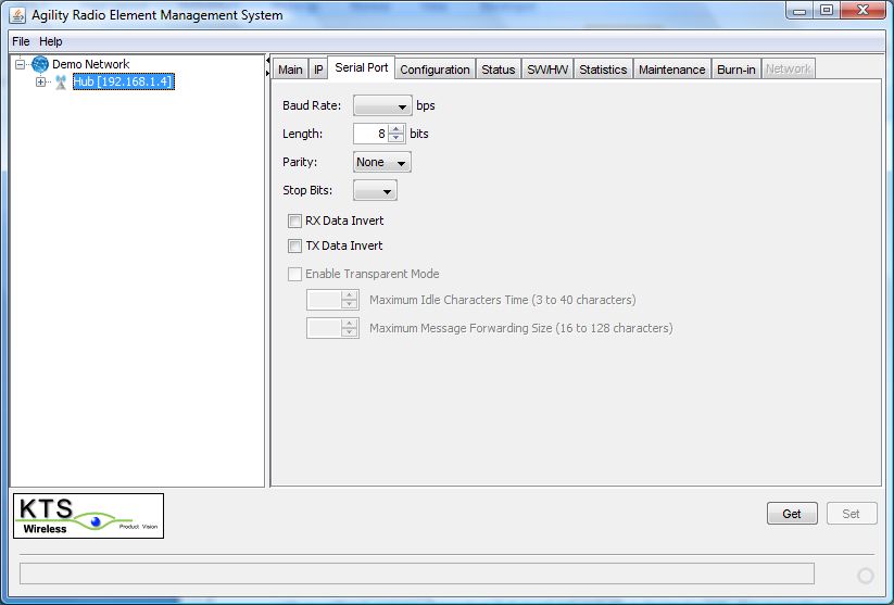
3. The Serial Port tab is shown. If a site is configured as a Remote, both the Ethernet and Serial
ports are active. For Hub sites, either the Serial or Ethernet ports can be used but not both. If
serial data destined for remotes is exchanged at the Hub using port 3123 over the Ethernet
connection, then both ports at the remote sites can be used. This unique port is reserved for
data that is routed to the serial ports at all remotes. All other Ethernet traffic at the Hub is
routed to the appropriate remote site and sent to its Ethernet port. If the serial port is to be
used at the Hub, then the Enable Transparent Mode check box must be set on the Serial Port
tab. Otherwise, the Hub ATRs serial port remains inactive and it is assumed traffic on port 3123
will be routed to the Remote sites serial ports. IF the Hub’s serial port is enabled then traffic on
the Ethernet port is ignored.

 If the Serial port is used, select the desired baud rate from the pull-down menu. Next, select
the character length, Parity and Number of Stop Bits from the associated pull-down menus.

The received data from the ATR to the user device can be inverted by checking the RX Data
Invert box. Likewise, the transmit data to the ATR from the user device can also be inverted by
checking the TX Data Invert box.

The serial port protocol used is always Transparent Mode. This mode supports most
asynchronous protocols like Allen-Bradley, Modbus and others. User data bytes received by the
ATR over the serial port are ‘collected’ into a packet until the line goes idle (no activity for N
configurable character times). After this wait time, the packet is immediately transmitted over
the wireless link. All packets received over the wireless link are immediately transmitted out
over the serial port.

After all of the fields on the tab have been entered, click on SET at the bottom. The EMS will
then store all the values in the ATR’s non-volatile memory. They will remain there permanently
until changed.
4. Open the Configuration Tab (See below). Open the Link Configuration pull-down menu by
clicking on the down arrow at the right. A list of available link configurations will appear. Select
the desired configuration from the numbered list. Those valid for the ATR are channel
bandwidths 50 kHz and smaller. The desired choice will appear in the Link Configuration field.
The Link Configuration parameter automatically sets the modulation format, MAC type, over-
the-air-data rate and channel size. All ATRs in the same network must use the same Link
Configuration.

Enter the desired Center frequency of the channel to be used. Care must be taken to obtain
proper approval for the use of this channel. This is a value in Hertz (Hz) and may be entered
with or without comma separators but must not include a decimal point. For example, an
authorized channel frequency of 162.2625 MHz must be entered as 162262500 or 162,262,500.
All frequencies must be divisible by 6,250. Note, only authorized frequencies consistent with
the installed RF Board type (VHF or UHF) will be accepted by the EMS (See Table 1).

Enter the desired RF Transmit Power. This is entered as an integer between 10 and 37 and in
units of dBm. The resolution is 0.1 dB. Ensure that this power level does not exceed the
applicable regulations.
Select Radio Type as Hub or Remote. The Hub is the single, master radio network that
communicates with all other radios. It must be able to communicate over the air to all
remotes. Devices connected to remote ATRs can be accessed by other remotes through the
Hub. This normally occurs automatically within the bridging software in the ATRs.

A Site Name can be assigned to the ATR that corresponds to site or location to help identify
which radio is it in the network (e.g., Pump Site 1). This allows the Network Operator to keep
track of the radio’s current location. Up to 15 characters can be entered.

After all of the fields on the tab have been entered, click on SET at the bottom. The EMS will
then store all the values in the ATR’s non-volatile memory. They will remain there permanently
until changed.

5. Open the Status tab (See below). This tab contains information about the current status of
the ATR. The definitions for the 5 indications are:
RSSI: Receive Signal Strength Indication. It is an estimate of the received signal power of the
most recently receive valid message following the Get. The units are dBm and range from
about -120 to -30.

Temperature: This is an estimate of the temperature inside the ATR (will be higher than
outside temperature). A sensor inside the radio records this internal temperature. The current
value is compared to high and low preset temperature thresholds (factory defaults) to
determine if a temperature fault is present. If so, this field on the tab will be highlighted in red.
The ATR Summary Fault LED will also be illuminated. The specified operating temperature
range of the ATR is -30 to +60 degrees C (outside air temperature). The internal temperature
reported by this sensor should be below 75 deg C.

Synth: This refers to the ATR’s internal Frequency Synthesizer. A fault can be caused by
entering an invalid frequency or a hardware failure within the ATR. Valid frequencies must be
divisible by 2,500 or 6,250 Hz (depending on frequency band selected) and must be within the
authorized range of the RF Card installed in the ATR (See Section 1). A Synth fault will prevent
the Radio from transmitting. If a fault occurs, make sure the Center Frequency is entered
properly. If it has been, a hardware failure has likely occurred.
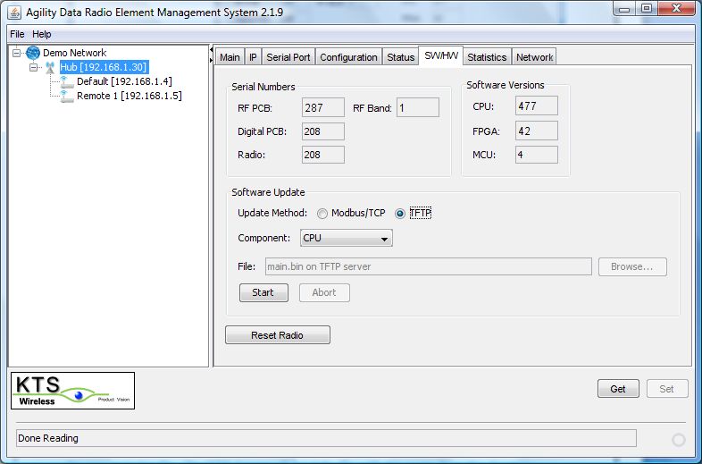
6. Open the SW/HW tab (see below). This tab show the serial numbers for the RF and Digital
circuit boards installed in the ATR and the top-level, ATR serial number. This top-level assembly
number should match the printed label on the back of the Radio. These values are stored in the
ATR’s memory and cannot be changed by the user. The RF Band supported is also indicated.

The software version numbers for the CPU, FPGA and MCU. The CPU and FPGA are processors
on the Digital Board. The MCU is a processor on the RF Board and cannot be updated in the
field. The CPU and FPGA software elements are updated from time to time by KTS Wireless and
made available to customers. Updated versions can be loaded on to a TFTP Server with the IP
address that is recorded on the IP tab (Firmware Server). Once loaded on a server accessible by
the ATR, it can be downloaded to the ATR by performing the following:

       1. Select TFTP as the Update Method. See Section 5 for additional details.

       2. Select CPU or FPGA as the software Component to be updated

        3. Verify that the TFTP Server is running and the main.bin and fpga.bin files are loaded
in the appropriate directory. Note the file names cannot be changed.

       4. Verify that the TFTP Server interface and current directly are properly configured.

                                                                   Directory where main.bin (CPU SW)
                                                                   and fpga.bin (FPGA SW) are stored.

                                                                   Must be the same as the
                                                                   Firmware Server address on the
                                                                   IP Tab.

      5. Click on the Start button. Verify that data is being transferred by the TFTP Server
(message displayed).

        6. The ATR will reset after the download is complete. This will be indicated by all LEDs
flashing briefly. After about 7 seconds, the rebooting will complete.
7. Click on the GET button (lower right) and verify the appropriate SW Version number
(CPU or FPGA) has changed to the proper number. If no change in this version number occurs,
the download was not accomplished successfully.
The MCU software cannot currently be updated in the field.
Modbus/TCP can also be used as the method of software updating. This method does not
require a TFTP Server or any other supporting software. The following outlines the steps
required for this method:
1. Select Modbus/TCP as the Update Method. See Section 5 for additional details.
2. Select CPU or FPGA as the software Component to be updated3. Press Browse and select the path to the appropriate download file (main.bin for the
CPU or fpga.bin for the FPGA). Note, these names cannot be changed.
4. Click on the Start button.
5. The ATR will reset after the download is complete (10-20 secs). This will be indicated
by all LEDs flashing briefly. After about 7 additional seconds, the rebooting will complete.
6. Click on the GET button (lower right) and verify the appropriate SW Version number
(CPU or FPGA) has changed to the proper number. If no change in this version number occurs,
the download was not accomplished successfully.
7. Open the Statistics tab (See below). This tab includes traffic statistics kept by the Radio
along with operating temperature ranges (recent high and low limits). Collection of these
statistics starts when the Start button is pressed. All values are first cleared and counts
continue until each Update Period ends. When this period ends the accumulated counts are
displayed in the appropriate fields. Another collection period begins immediately after the
previous one ends. The statistics fields are updated with new counts for the last completed
collection period. This process continues until the Stop button is pressed. Temperature
extremes are not reset for each collection period but are remembered for the duration of the
monitoring session (i.e., until the Stop button is pressed).8. Open the Network tab (See below). This tab contains a list of all the remote ATR’s that are currently connected over the wireless link to the hub. Click on the Start button at the bottom of the tab. The hub radio will report all of the remote ATRs that have joined the wireless network with the Hub and display the RSSI (power level of last message received from that ATR). This list is automatically updated by the EMS once per few seconds until the Stop button is pressed. The Node Count is the total number of ATRs joined.
The Node name is the serial number of the ATR.
                                                 Serial Number of Remote that joined

                                                 RSSI of last packet from the Remote
5.0 Upgrading Software
The software in the ATR can be upgraded in the field to support new features or correct any
problems. This can be done locally through the Ethernet port and remotely over the air if one
of the IP-based link configurations is used (See Section 2.0). The radio has two types of
software which can be field-upgraded (CPU and FPGA). The CPU code controls the higher-level
functionality within the radio including the MAC, networking layers, network management and
user interfaces. The FPGA code supports the Physical layer.
Software upgrades for both the CPU and FPGA code are provided periodically by KTS wireless.
Users are notified when these become available. Some upgrades may be mandatory to resolve
problems while others may be optional if they include new features. Release notes will be
available for each new version outlining the changes. Some new releases may require
additional fees and/or licensing agreements.
The following procedure outlines the steps involved in a field software upgrade:
1. The user will be emailed a compressed (zip) file containing the new version of the software.
This may include one or two files. The CPU and FPGA code can be upgraded separately or in
certain cases must be upgraded simultaneously. If two files are included, both must be
upgraded at the same time to ensure compatibility.
2. The email attachments will include one or both of the following files:
main.zip
fpga.zip
The files will be zipped with a password that will be provided in the email with the files or a
separate one sent to the same email address.
3. Using WinZip or compatible file compression program, extract the file(s) and store on your
PC. It may be convenient to create a folder containing these software upgrade files. Do not
rename these files. They must use the same names as sent or the automatic download
process outlined below will not work. Verify the file size of each is 500 to 700 KB. Do notattempt to load a file that is smaller, as the file has likely been corrupted in the
zipping/emailing/unzipping process.
The EMS supports two methods of Downloading. One uses the TFTP protocol and Server and
the other uses the Modbus/TCP protocol which is supported directly by the EMS. The following
sections describe the procedure for both methods.
TFTP Downloading Method
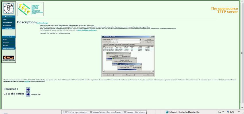
1. If not done previously, download the open source TFTP Server to your PC. This is available
free at the following website:
http://tftpd32.jounin.net/
Click here to download
Download the TFTP Server software (latest version), unzip and store on the PC Desktop.
Double-click on the icon to start the server to launch the tftpd32 server on the PC.The following screen will appear. Select the directory from the Browse list and the file where
the actual software download is stored from the Show Dir list. The Server Address should
contain the IP address of the PC.
Use the cmd command and enter ipconfig to verify the current IP address of your PC. These
will normally match when the tftpd32 software is started.
2. Start the EMS software by clicking on the following Desktop icon (see Section 4.0).
EMS_2.3.23.6.jarLogin using your assigned password and click on the SW/HW tab as shown below: Click on the GET button (bottom right) to display the current versions of the CPU and FPGA software. 3. On the IP tab verify that the Firmware Server address is set to your PCs IP address and matches the address indicated in the Server Interface field of the tftpd32 Server. If not, change the Firmware Server address on the IP tab and press the SET button (lower right) and the Network Restart button. Click on the Get button to verify the new Firmware Server address is correct. Return to the SW/HW tab. 4. Select TFTP as the Update Method (center of the screen). If the software file to be upgraded is main.bin, select CPU as the Component. Click the Start button. The ATR will automatically establish a connection with the TFTP Server on your PC to request the new main.bin file. The TFTP Server will send the file with this name from the directory specified in the Current Directory field on the tftpd32 screen (Desktop or other specified folder). The download will take about 10-15 seconds. Upon completion the ATR will be automatically reset. A brief flashing of the three LEDs will occur when the reset is done. The radio will complete rebooting
after the reset in about 7-10 seconds. After this reboot, click on the GET button on the SW/HW
tab. If the download was successful, a new (higher) version number will appear in the CPU
version field.

5. If the software file to be upgraded is fpga.bin, Select FPGA as the Component. Click on the
Start button. The ATR will establish a connection with the TFTP Server on your PC to request
the new fpga.bin file. The TFTP Server will send the file with this name from the directory
specified in the Current Directory field on the tftpd32 screen (Desktop or other specified
folder). This download will take about 60 seconds. Upon completion the radio will be
automatically reset. A brief flashing of the LEDs will occur when the reset is done. The radio
will complete rebooting after the reset in about 7-10 seconds. After this reboot, click on the
GET button on the SW/HW tab. If the download was successful, a new (higher) version number
will appear in the FPGA version field.

The radio should now be using the updated software. Steps 4 and 5 above can be done
separately if only one of the two software types is to be upgraded.

Modbus/TCP Downloading Method

2. Start the EMS software by clicking on the following Desktop icon (see Section 4.0).

                                          EMS_2.3.23.6.jar

Login using your assigned password and click on the SW/HW tab as shown below:
Click on the GET button (bottom right) to display the current versions of the CPU and FPGA software. 3. Select Modbus/TCP as the Update Method (center of the screen). If the software file to be upgraded is main.bin, select CPU as the Component. Click on the Browse button and navigate to the main.bin file on the PC running the EMS. After the path to the file has been selected, click the Start button. The EMS will send the file with this name from the directory specified. The download will take about 10-15 seconds. Upon completion the ATR will be automatically reset. A brief flashing of the three LEDs will occur when the reset is done. The radio will complete rebooting after the reset in about 7-10 seconds. After this reboot, click on the GET button on the SW/HW tab. If the download was successful, a new (higher) version number will appear in the CPU version field. 4. If the software file to be upgraded is fpga.bin, Select FPGA as the Component. Click on the Browse button and navigate to the fpga.bin file on the PC running the EMS. After the path to the file has been selected, click the Start button. The EMS will send the file with this name from the directory. This download will take about 60 seconds. Upon completion the radio will be automatically reset. A brief flashing of the LEDs will occur when the reset is done. The radio
will complete rebooting after the reset in about 7-10 seconds. After this reboot, click on the
GET button on the SW/HW tab. If the download was successful, a new (higher) version number
will appear in the FPGA version field.

The radio should now be using the updated software. Steps 3 and 4 above can be done
separately if only one of the two software types is to be upgraded.
You can also read