ALTITUDE ALLOY - BikeAction
←
→
Page content transcription
If your browser does not render page correctly, please read the page content below

PL ATFORM MANUAL   Rider:      Jesse Melamed
                   Photo:      Margus Riga
                   Location:   North Vancouver, BC

ALTITUDE ALLOY
Altitude Alloy Platform Manual             Table of Contents   2

TABLE OF CONTENTS

Introduction                           3

Shrediquette                           3

Getting to know your bike              4

Basic setup                            5

Shock eyelet bearing                   6

Shock setup                            7

RIDE-9                                11

RM two-position axle                  12

Cable routing how to                  13

Critical dimensions                   17

Pro tips & tricks                     18

Exploded view                         18

Full list of parts                    19

Small parts kit                       22

Warranty information                  25

Rider:          Jesse Melamed
Photo:          Margus Riga
Location:       North Vancouver, BC
Altitude Alloy Platform Manual                                                                     Introduction & Shrediquette          3

INTRODUCTION

The Altitude will be our key platform for enduro racing and aggressive trail riding. Ridden        Rider:         ALN
                                                                                                   Photo:         Margus Riga
by the Rocky Mountain Race Face Enduro Team, this bike is fast. Already race proven with
                                                                                                   Location:      North Vancouver, BC
Jesse's win at the EWS in Zermatt, Switzerland, the redesigned Altitude is now more capable
than ever.

The goal with the redesign was to create a bike that would be competitive on today's
racetracks while still being a ton of fun for those getting out on weekends. We might not all
smash racetracks and stand on podiums like Jesse Melamed, but we can all relate to the
feeling of committing to ride a little faster or hitting that feature you usually skip over. The
Altitude has everything that you need to take your riding to the next level.

This manual contains important safety, maintenance and user information. Read and
understand it thoroughly before your first ride on your new Rocky Mountain bicycle. This
material applies only to the specific platform you have chosen and should be used in
conjunction with your Rocky Mountain Owner’s Manual, which is included with your bike.
Please read the Owner’s Manual before your first ride. If you do not have a copy of the
Owner’s Manual, you can get it from your nearest authorized Rocky Mountain dealer.

SHREDIQUETTE

Riders
Always be courteous to other trail users. Use extra caution around domestic animals, such as
dogs and horses. Give other trail users right-of-way in all situations, during both climbing and
descending.

Trail
Only ride your bicycle on trails and paths sanctioned for bicycle use. Follow all local laws
and regulations. As for all trail users, care should be taken to avoid impacts on the trail or
environment. Do not skid on or modify trails.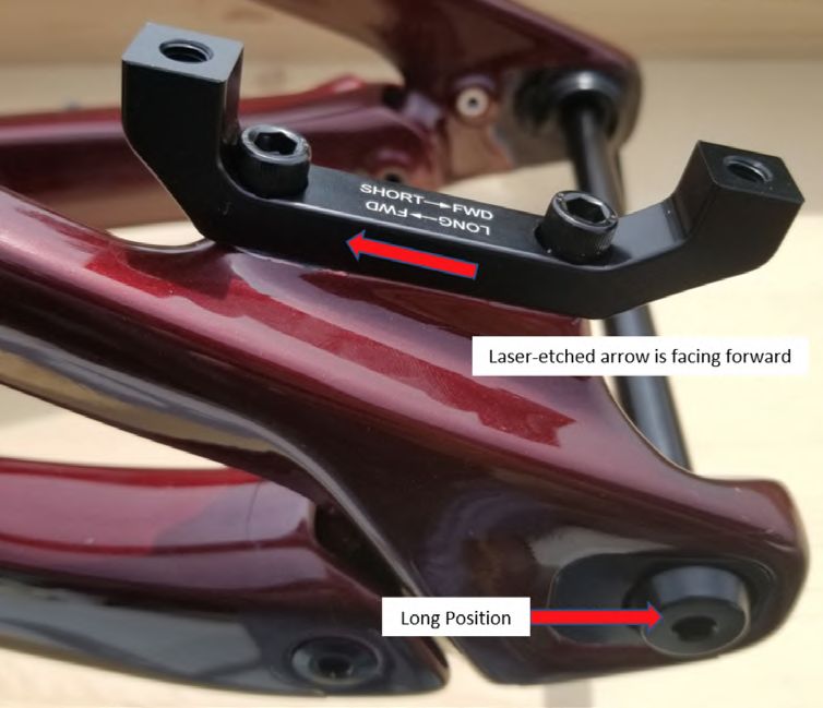
Altitude Alloy Platform Manual                                                                        Getting to know your bike       4

GETTING TO KNOW YOUR BIKE

Technical details
•	Designed to win enduro races, the Altitude’s refined carbon    •	The result is a sensitive yet supportive feeling platform
   frame means it is tough enough to withstand aggressive            that’s dialed in for bottom out resistance with both coil and
   descents and light enough to make easy work of the                modern air shocks.
   liaisons between stages.
                                                                  •	Bearing shields throughout help prevent contamination
•	The RIDE-9™ adjustment system allows riders to quickly            from gnarly trail conditions or post-ride wash stations.
   fine tune their geometry and suspension with a pair of Allen
                                                                  •	Dual row bearings at the dropouts for a stiffer rear triangle.
   keys.

                                                                  •	The fully enclosed internal routing on our carbon models
•	We’ve increased the reach, made the seat tube angle
                                                                     and large open ports on alloy allow for easy cable and hose
   steeper, lengthened the chainstays, and designed for a 44
                                                                     installations.
   mm offset fork. The Altitude was designed for speed, while
   maintaining its trail manners.                                 •	Integrated OneUp chain guide, with 2-bolt ISCG05 for
                                                                     mounting a bashguard, keeping your chain on and your ring
•	Improved small bump compliance and reduced pedal kick,
                                                                     intact.
   while providing increased mid-stroke sensitivity and end-
   stroke progression.                                            •	Integrated downtube protector and shuttle guard.

•	New, smaller sealed bearings at the shock eyelet               •	All frame sizes are water bottle compatible.
   dramatically improve shock sensitivity (aftermarket shock
   compatible).
Altitude Alloy Platform Manual                                                                                                       Basic setup     5

BASIC SETUP

There are several variables that can be manipulated to fine tune the setup of your suspension. These are some basic guidelines to get you in the
ballpark, and you should experiment to see what best suits you from there. The first step is to set your sag. Sag refers to how much the suspension
moves under just the weight of the rider (including all riding accessories). Air pressure or coil spring rate and preload is adjusted until the desired
amount of sag is measured.

Please observe the minimum and maximum amount of preload recommended by the manufacturer for a given coil spring. If you need to change the
spring rate, please note you must remove the eyelet bearings to remove the coil spring.

Shock sag                                                                             Fork sag
We recommend approximately 30–35% sag for this platform.                              We recommend approximately 15–20% sag for this platform.

Regular Kinematic (Size MD - LG - XL)

                                     Sag
                                  30%: 18 mm
                                  35%: 21 mm

                                                                                                                       Fork travel
                                                                                                                        170 mm

                                        Shock stroke                                                                   Sag
                                        230 x 60 mm                                                                 15%: 26 mm
                                                                                                                    20%: 34 mm

Light Kinematic (Size SM)

                                       Sag
                                   30%: 16.5 mm
                                   35%: 19.5 mm

                                        Shock stroke
                                        210 x 55 mm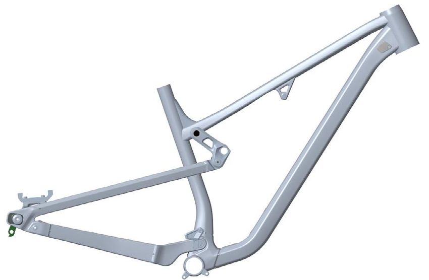
Altitude Alloy Platform Manual                                                                                                  Basic setup          6

SHOCK EYELET BEARING

Service
Your frame is equipped with cartridge bearings in the rear eyelet, allowing for better small-bump compliance. These bearings are carried by cups
that have a very firm press fit into the shock shaft.

If you have your shock serviced, we highly recommend                               If you do not have the Rocky Mountain Bearing Eyelet Tool
removing these components, as suspension service centres                           Kit, use a blind bearing puller:
cannot guarantee they will be returned.
                                                                                   • Use a blind bearing puller (8 mm extension) to remove both
To remove the system, follow these steps:                                            bearings.

• Use the Rocky Mountain Bearing Eyelet Tool Kit                                   • Remove the centre sleeve.
  (Part# 1810031)
                                                                                   • Use the blind bearing puller (10 mm extension) to remove
• Install the top hat piece on one side of the bearing eyelet                        the empty cups.

• Next, install one of the cup removal tools over the bearing                      NOTE: the inner diameter of the cups is 11 mm, which means
  cup with the top hat piece installed.                                            the 12 mm extension won’t fit (So don't force it); Use the 10
                                                                                   mm extension.
• Thread the M8 screw snuggly against the top hat piece
                                                                                   To install new cups, use a bearing press or vice with soft jaws
• Install the other cup removal tool over the other bearing cup
                                                                                   installed, making sure to press on the outer edge of the cups,
• Thread the M8 screw all the way in until it starts pushing on                    and don’t forget the centre spacer sleeve between the cups.
  the other side. It is contacting the inside of the top hat
  piece.

• Keep threading until one of the cups is full pushed out.

• Next insert the drift tool through the shock eyelet and rest it
  firmly against the bearing cup that is still pressed in the
  shock eyelet.

• Gently, but firmly, hammer the drift tool until the bearing cup
  is fully removed from the shock eyelet.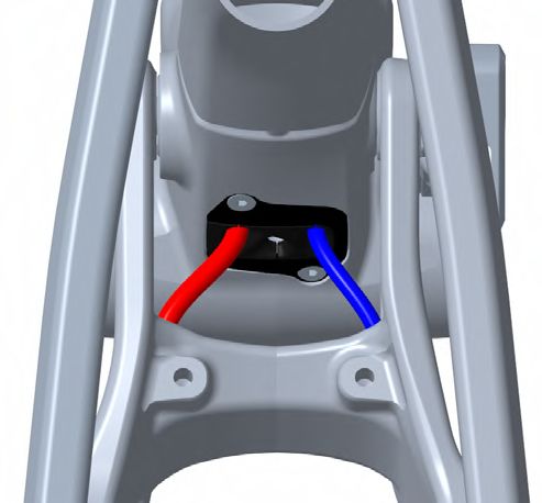
Altitude Alloy Platform Manual                                                                                                 Shock setup        7

ALTITUDE SPRING CHART

Rebound                                                                           Compression
Rebound adjustment controls how quickly your suspension                           Low speed compression (LSC) controls rider weight shifts,
returns to full extension after it hits a bump. Too much rebound                  pumping through terrain, G-outs, and other slow inputs. Too
control, and the fork or shock will move too slowly, sinking                      much LSC will result in a harsher ride feel; too little LSC will
deeper and deeper into its travel under repeated hits, which                      result in a ride feel that’s too soft and unresponsive.
will feel harsh. Too little, and the suspension can spring back
too quickly, causing a loss of traction and control. Follow the
manufacturer’s recommendations for base settings, and
experiment to find your happy place.

                             2021 ALTITUDE 230x60 FOX DHX2 COIL SHOCK *Count clicks from Closed: 0 Clicks = Closed*

   RIDER WEIGHT           STEEL SPRING    FOX SLS SPRING                 RECOMMENDED       RECOMMENDED        RECOMMENDED        RECOMMENDED
                                                           SHOCK SAG
      LBS / KG              WEIGHT           WEIGHT                       LSR SETTING       HSR SETTING        LSC SETTING        HSC SETTING

      100 / 45                   300           300          19-21 mm         10-11               6-7               14-15               6-7

      110 / 50                   300           325          19-21 mm         9--11               6-7               14-15               6-7

      120 / 55                   350           350          19-21 mm          8-9                6-7               14-15               6-7

      130 / 59                   350           375          19-21 mm          8-10               6-7               13-14               6-7

      140 / 64                   400           400          19-21 mm          6-7                5-6               12-13               5-6

      150 / 68                   400           425          19-21 mm          6-7                5-7               11-13               5-6

      160 / 73                   450           450          19-21 mm          5-6                4-5               9-10                5-6

      170 / 77                   450           475          19-21 mm          5-6                4-5               9-11                4-6

      180 / 82                   500           500          19-21 mm          4-5                4-5               9-10                4-5

      190 / 86                   500           525          19-21 mm          4-5                3-5                7-9                3-4

      200 / 91                   550           550          19-21 mm          3-4                3-4                6-7                3-4

      210 / 95                   600                        19-21 mm          2-3                2-3                5-6                2-3

      220 / 100                  600                        19-21 mm          2-3                2-3                5-6                2-3

      230 / 105                  650       Not Available    19-21 mm          1-2                1-2                4-5                1-2

      240 / 109                  700                        19-21 mm          1-2                0-1                3-4                0-1

      250 / 114           Not Available                     19-21 mm      Not Available      Not Available     Not Available      Not Available

                             2021 ALTITUDE 210x55 FOX DHX2 COIL SHOCK *Count clicks from Closed: 0 Clicks = Closed*

   RIDER WEIGHT           STEEL SPRING    FOX SLS SPRING                 RECOMMENDED       RECOMMENDED        RECOMMENDED        RECOMMENDED
                                                           SHOCK SAG
      LBS / KG              WEIGHT           WEIGHT                       LSR SETTING       HSR SETTING        LSC SETTING        HSC SETTING

      100 / 45                   300           325          17-19 mm          9-11               6-7               14-15               6-7

      110 / 50                   350           350          17-19 mm          8-9                6-7               14-15               6-7

      120 / 55                   350           375          17-19 mm          8-10               6-7               13-14               6-7

      130 / 59                   400           400          17-19 mm          6-7                5-6               12-13               5-6

      140 / 64                   400           400          17-19 mm          6-7                5-6               12-13               5-6

      150 / 68                   400           425          17-19 mm          6-7                5-7               11-13               5-6

      160 / 73                   450           450          17-19 mm          5-6                4-5               9-10                5-6

      170 / 77                   450           475          17-19 mm          5-6                4-5               9-11                4-6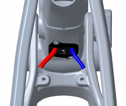
Altitude Alloy Platform Manual                                                                                         Shock setup      8

ALTITUDE SPRING CHART

                           2021 ALTITUDE 230x60 FOX FLOAT X2 AIR SHOCK *Count clicks from Closed: 0 Clicks = Closed*

   RIDER WEIGHT                                                          RECOMMENDED    RECOMMENDED     RECOMMENDED      RECOMMENDED
                                 FOX FLOAT X2 PSI         SHOCK SAG
      LBS / KG                                                            LSR SETTING    HSR SETTING     LSC SETTING      HSC SETTING

      100 / 45                         130                 19-21 mm          12-14           5-6            14-16              6-7

      110 / 50                         140                 19-21 mm          11-13           5-6            14-16              6-7

      120 / 55                         150                 19-21 mm          10-12           5-6            13-15              6-7

      130 / 59                         160                 19-21 mm          9-11            4-5            13-15              6-7

      140 / 64                         170                 19-21 mm          8-10            4-5            12-14              5-6

      150 / 68                         180                 19-21 mm           7-9            4-5            11-13              5-6

      160 / 73                         190                 19-21 mm           7-9            3-4            10-12              5-6

      170 / 77                         200                 19-21 mm          6-8             3-4             9-11              4-5

      180 / 82                         210                 19-21 mm          6-8             3-4             8-10              4-5

      190 / 86                         220                 19-21 mm           5-7            2-3             7-9               4-5

      200 / 91                         230                 19-21 mm          4-6             2-3             6-8               4-5

      210 / 95                         240                 19-21 mm          3-5             2-3             5-7               3-4

      220 / 100                        250                 19-21 mm          2-4             2-3             4-6               3-4

      230 / 105                        260                 19-21 mm          2-4             1-2             2-4               3-4

      240 / 109                        270                 19-21 mm           1-3            1-2             2-4               3-4

      250 / 114                        280                 19-21 mm           1-3            1-2             2-4               2-3

                           2021 ALTITUDE 210x55 FOX FLOAT X2 AIR SHOCK *Count clicks from Closed: 0 Clicks = Closed*

   RIDER WEIGHT                                                          RECOMMENDED    RECOMMENDED     RECOMMENDED      RECOMMENDED
                                 FOX FLOAT X2 PSI         SHOCK SAG
      LBS / KG                                                            LSR SETTING    HSR SETTING     LSC SETTING      HSC SETTING

      100 / 45                         140                 17-19 mm          11-13           5-6            14-16              6-7

      110 / 50                         150                 17-19 mm          10-12           5-6            13-15              6-7

      120 / 55                         160                 17-19 mm          9-11            4-5            13-15              6-7

      130 / 59                         170                 17-19 mm          8-10            4-5            12-14              5-6

      140 / 64                         180                 17-19 mm           7-9            4-5            11-13              5-6

      150 / 68                         190                 17-19 mm           7-9            3-4            10-12              5-6

      160 / 73                         200                 17-19 mm          6-8             3-4             9-11              4-5

      170 / 77                         210                 17-19 mm          6-8             3-4             8-10              4-5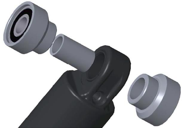
Altitude Alloy Platform Manual                                                                                                 Shock setup      9

ALTITUDE SPRING CHART

                                 2021 ALTITUDE 230x60 FOX DPX2 AIR SHOCK *Count clicks from Closed: 0 Clicks = Closed*

   RIDER WEIGHT                                                                      RECOMMENDED                      RECOMMENDED
                                     FOX DPX2 PSI             SHOCK SAG
      LBS / KG                                                                        LSR SETTING                LSC SETTING *IF AVAILABLE

      100 / 45                           150                   19-21 mm                   12                      Start open / Adjust to suit

      110 / 50                           160                   19-21 mm                  11-12                    Start open / Adjust to suit

      120 / 55                           170                   19-21 mm                   11                      Start open / Adjust to suit

      130 / 59                           180                   19-21 mm                  10-11                    Start open / Adjust to suit

      140 / 64                           190                   19-21 mm                   10                      Start open / Adjust to suit

      150 / 68                           200                   19-21 mm                  8-10                     Start open / Adjust to suit

      160 / 73                           210                   19-21 mm                   8                       Start open / Adjust to suit

      170 / 77                           220                   19-21 mm                   7-8                     Start open / Adjust to suit

      180 / 82                           230                   19-21 mm                   7                       Start open / Adjust to suit

      190 / 86                           240                   19-21 mm                   7                       Start open / Adjust to suit

      200 / 91                           250                   19-21 mm                   7                       Start open / Adjust to suit

      210 / 95                           260                   19-21 mm                  5-6                      Start open / Adjust to suit

      220 / 100                          270                   19-21 mm                   5                       Start open / Adjust to suit

      230 / 105                          280                   19-21 mm                   2-3                     Start open / Adjust to suit

      240 / 109                          290                   19-21 mm                   2                       Start open / Adjust to suit

      250 / 114                          300                   19-21 mm                   2                       Start open / Adjust to suit

                                 2021 ALTITUDE 210x55 FOX DPX2 AIR SHOCK *Count clicks from Closed: 0 Clicks = Closed*

   RIDER WEIGHT                                                                      RECOMMENDED                      RECOMMENDED
                                     FOX DPX2 PSI             SHOCK SAG
      LBS / KG                                                                        LSR SETTING                LSC SETTING *IF AVAILABLE

      100 / 45                           160                   17-19 mm                  11-12                    Start open / Adjust to suit

      110 / 50                           170                   17-19 mm                   11                      Start open / Adjust to suit

      120 / 55                           180                   17-19 mm                  10-11                    Start open / Adjust to suit

      130 / 59                           190                   17-19 mm                   10                      Start open / Adjust to suit

      140 / 64                           200                   17-19 mm                  8-10                     Start open / Adjust to suit

      150 / 68                           210                   17-19 mm                   8                       Start open / Adjust to suit

      160 / 73                           220                   17-19 mm                   7-8                     Start open / Adjust to suit

      170 / 77                           230                   17-19 mm                   7                       Start open / Adjust to suit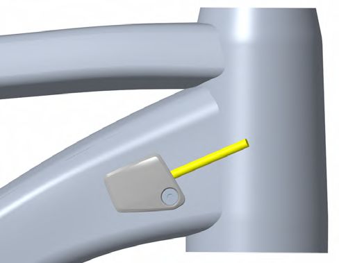
Altitude Alloy Platform Manual                                                                                          Shock setup      10

ALTITUDE SPRING CHART

                       2021 ALTITUDE 230x60 ROCK SHOX DELUXE AIR SHOCK *Count clicks from Closed: 0 Clicks = Closed*

   RIDER WEIGHT                                                               RECOMMENDED                      RECOMMENDED
                                 ROCK SHOX SDLX PSI      SHOCK SAG
      LBS / KG                                                                 LSR SETTING                LSC SETTING *IF AVAILABLE

      100 / 45                          120              19-21 mm                   7                      Start open / Adjust to suit

      110 / 50                          130              19-21 mm                   7                      Start open / Adjust to suit

      120 / 55                          140              19-21 mm                  6-7                     Start open / Adjust to suit

      130 / 59                          150              19-21 mm                  6-7                     Start open / Adjust to suit

      140 / 64                          160              19-21 mm                   6                      Start open / Adjust to suit

      150 / 68                          170              19-21 mm                  5-6                     Start open / Adjust to suit

      160 / 73                          180              19-21 mm                  5-6                     Start open / Adjust to suit

      170 / 77                          190              19-21 mm                   5                      Start open / Adjust to suit

      180 / 82                          200              19-21 mm                  4-5                     Start open / Adjust to suit

      190 / 86                          210              19-21 mm                  4-5                     Start open / Adjust to suit

      200 / 91                          220              19-21 mm                   4                      Start open / Adjust to suit

      210 / 95                          230              19-21 mm                  4-3                     Start open / Adjust to suit

      220 / 100                         240              19-21 mm                  4-3                     Start open / Adjust to suit

      230 / 105                         250              19-21 mm                   3                      Start open / Adjust to suit

      240 / 109                         260              19-21 mm                  3-2                     Start open / Adjust to suit

      250 / 114                         270              19-21 mm                  3-2                     Start open / Adjust to suit

                       2021 ALTITUDE 210x55 ROCK SHOX DELUXE AIR SHOCK *Count clicks from Closed: 0 Clicks = Closed*

   RIDER WEIGHT                                                               RECOMMENDED                      RECOMMENDED
                                 ROCK SHOX SDLX PSI      SHOCK SAG
      LBS / KG                                                                 LSR SETTING                LSC SETTING *IF AVAILABLE

      100 / 45                          130              17-19 mm                   7                      Start open / Adjust to suit

      110 / 50                          140              17-19 mm                  6-7                     Start open / Adjust to suit

      120 / 55                          150              17-19 mm                  6-7                     Start open / Adjust to suit

      130 / 59                          160              17-19 mm                   6                      Start open / Adjust to suit

      140 / 64                          170              17-19 mm                  5-6                     Start open / Adjust to suit

      150 / 68                          180              17-19 mm                  5-6                     Start open / Adjust to suit

      160 / 73                          190              17-19 mm                   5                      Start open / Adjust to suit

      170 / 77                          200              17-19 mm                  4-5                     Start open / Adjust to suit
Altitude Alloy Platform Manual RIDE-9 11
RIDE-9
The RIDE-9™ adjustment system allows riders to quickly fine tune their geometry with a pair of Allen keys. Nine configurations are possible
thanks to a pair of rotating chips. Geometry setup is a complex artform with huge variables in rider style, preference, terrain, and ability. We do
recommend the use of professional services, but we also believe that learning to dial in your own bike is the best way to fully understand its
performance. When adjusting your RIDE-9 position, make gradual, incremental changes, take notes, and be methodical. Don’t adjust in a hurry
before a big ride. Take your time and enjoy the process.
Go HERE to download the full guide
READY FOR ANY TRAIL
The RIDE-9™ adjustment system allows
you to quickly fine-tune your geometry and
suspension with a pair of Allen keys.
S T E E PE R
H E A D -T U B E A N G L E
L ES S
PRO G R ES S I V E
S U S PE N S I O N
9
6
8
5
2
7
4
1
S L AC K ER
H E A D -T U B E A N G L E
MORE
5 9
PRO G R ES S I V E
1
S U S PEN S I O N
Position 1
S L AC K
tability at high speeds.
S
Recommended for
more aggressive trail
1 riding.
9 5
5 9
1
Position 5
N EU T R A L
Balanced handling
and stability.
1
9 5
5 9
1
Position 9
STEEP
Quicker handling.
Recommended for
better climbing traction.
1
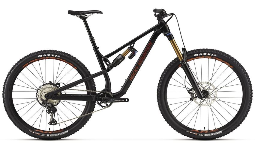
9 5Altitude Alloy Platform Manual RM two-position axle 12 RM TWO-POSITION AXLE USER MANUAL The 2021 Altitude frame, in both alloy and carbon, is equipped with a 2-position axle dropout. This allows the user to choose a short or long rear- center length that suits their personal preferences. To match the position of the rear axle to the brake caliper, the frame is also equipped with a unique Rocky Mountain brake adapter. It is designed to fit both axle positions and ensure that the brake caliper is properly positioned in relation to the rotor with maximum clamping surface area. This adapter comes with laser etched instruction regarding its required mounting orientation in relation to the chosen axle position. Short ----> FWD means the arrow should be pointing forward when the axle is in the short position. Long ----> FWD means the arrow should be pointing forward when the axle is in the long position.
Altitude Alloy Platform Manual                                                                                            Cable routing how to      13

CABLE ROUTING HOW TO

Removing the rear wheel and rear shock will allow you to cycle the rear triangle and give better access to direct the housing in the area between
the chain stay and main pivot. Cycling the rear triangle as you push the housing forward also reduces friction as the housing moves through the
bottom bracket port.
Altitude Alloy Platform Manual                                                                           Cable routing how to       14

REPLACING/INSTALLING REAR DERAILLEUR CABLE HOUSING

1. Remove non-drive side head tube port cover.                    4. Guide the housing into the housing port above the bottom
                                                                  bracket. Make sure you insert the derailleur housing into the
                                                                  port labeled “Shift.”
                                                                  a. Re-use pic from #1.

2. If replacing the old housing, cut a new piece to the same
length. If you don’t have the old piece, approximate the length
required and cut a slightly longer portion.

                                                                  5. Push the cable from the rear until it appears at the head tube
                                                                  port. Fish it out with a pick or a bent spoke.
3. Beginning from the rear of the bike, begin feeding the
housing into the cable opening on the drive side chain stay.
Push the cable forward and simultaneously twist the housing.

                                                                  6. Install the foam sleeve over the housing. You will need to
                                                                  push the foam down the housing until the foam is fully inserted
                                                                  inside the frame.
                                                                  a. Pic required of the foam sleeve on the derailleur housing

                                                                  7. Once the housing is installed, re-install the headtube port.
Altitude Alloy Platform Manual Cable routing how to 15
REPLACING/INSTALLING REAR HYDRAULIC BRAKE HOSE
Note: The instructions listed below are for a hydraulic brake with the hose attached to the caliper but not lever. Lever will have to reconnected and
bleed according to manufacturing specifications once hose has been installed.
1. Remove non-drive side head tube port cover for standard 4. Guide the brake hose into the housing port above the
rear brake lever position (Right-hand side) or drive side head bottom bracket. Make sure you insert the derailleur housing
tube port cover for moto / reverse rear brake lever position into the port labeled “Brake”. Any brake port will do.
(left-hand side). a. Pic required of the port with the hose inserted into the
standard port
2. Place the rubber grommet onto the hydraulic hose and slide
it back towards the brake caliper. Ensure the grommet is in the 5. Push the brake hose from the rear until it comes out at the
correct orientation. head tube port. Fish it out with a pick or a bent spoke.
a. Pic required of the housing exiting the open alloy head tube
port
3. Push the hose forward and simultaneously twist the hose 6. Before you re-attach the hose to the brake lever, install the
until it comes out at the forward end of the chain stay foam sleeve over the hose. You will need to push the foam
housing down the hose until it is fully inserted inside the frame.
a. Pic required of the foam housing installed on the brake hose.
7. Once the hose is re-attached to the brake lever, re-install
the headtube port.
a. Pic required of the headtube port installed with the housing
coming throughAltitude Alloy Platform Manual Cable routing how to 16
REPLACING/INSTALLING DROPPER POST HOUSING
The alloy frame has a natural guiding surface built above the bottom bracket which helps the housing transition from the seat tube to the down
tube and up towards the head tube port.
1. Remove drive side head tube port cover. 5. Before you re-attach the seatpost housing to the dropper
a. Pic required of the port cover on the frame post lever, install the foam sleeve over the housing. You will
need to push the foam housing down the hose until it is fully
inserted inside the frame.
a. Pic required of the housing entering seat tube and exiting
the headtube port.
6. Complete the dropper post installation as per the dropper
post manufacturer’s instructions.
2. If replacing the old housing, cut a new piece to the same
length. If you don’t have the old piece, approximate the length
required and cut a slightly longer portion
7. Once the seat post is correctly installed, re-install the
headtube port.
a. Pic required of the headtube port installed with the housing
coming through
3. Gently bend a 2-inch portion of the end of the seat post
housing. This will allow the housing to glide up the downtube
without catching on edges inside the frame
4. Beginning from the seat tube, begin feeding the housing
down. Push the housing down, gently twisting back and forth
until it makes it way up the down tube. Fish it out with a pick or
a bent spoke.
a. Pic required of the housing entering seat tube and exiting
the headtube port.Altitude Alloy Platform Manual Critical dimensions 17
CRITICAL DIMENSIONS
Ream depth (CARBON):
S: 210 mm Headset standard:
M: 235 mm (Both 27.5 and 29) ZS44 top
L: 250 mm ZS56 bottom
XL: 280 mm
Seatpost outer diameter: 30.9 mm
Seat QR inner diameter: 34.9 mm
Fork:
Altitude 27.5
Hardware: Max Travel = 170mm
25 mm x M8 Max Axle to Crown
Minimum insertion: Length = 567
100 mm
Altitude 29
Max Travel =170mm
Max Axle to Crown
Length = 586
Brake standard: Max tire size:
180 mm post mount 27.5 x 2.6 /
Max rotor: 29 x 2.6
203 mm Hardware:
Rocky Mountain Shock dimensions:
bearing eyelets Size SM
Rear hub spacing: 210 x 55 mm
Boost 148 mm Size MD – LG – XL
Chain guide standard:
Rocky Mountain Canadarm with 230x60mm
OneUp Components V2 TopGuide
Bashguard standard:
Two-bolt ISCG05
Bottom bracket standard: Max chainring size:
UDH Compatible
Press Fit BB92 36t
IN LONG POSITION ONLY:
Requires use of Sram
00.4318.005.033 rear axle
Shock fitment
We check clearances for many shocks but cannot guarantee compatibility with all makes and models.
Please contact your local dealer if you have a specific question regarding shock fitment.
Please note that you cannot run a 230mm eye-to-eye shock with a stroke longer than 60mm. The 62.5mm and 65mm stroke versions will
result in the link colliding with the frame due to the increased stroke
Approved Shocks (For 210x55 (Size SM) and 230x60 (Size MD-LG-XL)
Fox Marzocchi RockShox Cane Creek
• FLOAT DPS • Bomber RC • Deluxe • DB Coil
• FLOAT DPX2 • Super Deluxe Air • DBIL Coil
• FLOAT X2 • Super Deluxe Coil • DB Air
• DHX2 • DBIL AirAltitude Alloy Platform Manual Pro tips & tricks & Exploded view 18
PRO TIPS & TRICKS
• When tuning your suspension, write down your settings
so you can refer back to them. Better yet, use an online
• When assembling pivot bolts, use grease to “stick” any
spreadsheet on your phone!
spacers into place while you assemble.
• Use a 4 mm plastic housing ferrule to plug any unused
• Insert pivots through bearings/spacers so they sit flush
cable ports at the head tube.
with the inside of the inner race, holding washers in
place while you assemble.
• When removing your rear wheel, you can rest the chain on
the driveside seatstay protector to prevent it from dangling • Zip-tie a spare derailleur hanger to your saddle rails so you
awkwardly. always have one with you when you’re deep in the woods.
• When replacing shift or post housing, you can use
a RockShox reverb tool to simply pull a new piece of
housing right into place, without disturbing the inner
foam tubes. ROCKSHOX REVERB TOOL
EXPLODED VIEW
Please refer to the table for torque values and assembly details.
These views are provided to explain how your frame is assembled.
43
30
31
43
27
38
40
58
7
58 54 52
7 51 50
7 18 52
55 58
18
7 58 38 53
48 51
11 13
63
60 7
37
45
42 41
42 45
1 49
44 34
44
5 57 63
28 7 60 9
17 25
6
6 20 16 47 26
12 59 26
59 59 35 8 16 25 15
6 6 24
56 23 6
14 17
56 19 22
6
4 46 59
65 12 63
2 62 10
36
21
29 32
3
64
61 33
39Altitude Alloy Platform Manual Full list of parts 19
FULL LIST OF PARTS
Please refer to the small-parts kits available for purchase.
There are several kits that can help you maintain your bike for maximum trail performance: https://shop.bikes.com/collections/parts
These are available from your local dealer and on www.bikes.com.
# QTY ITEM PARTS NO. DESCRIPTION TORQUE (NM) INSTALLATION NOTES
1 1 ADAPTER 1801022 BRAKE ADAPTER
2 1 AXLE CHIP 3221001 AXLE FLIP CHIP, LEFT
3 1 AXLE CHIP 3221002 AXLE FLIP CHIP, RIGHT
APPLY GREASE TO AXLE SHAFT
AND THREADS. USE STAINLESS
4 1 AXLE, REAR 3227009 REAR AXLE 12X 173MM, HARD BLACK ANO 10
STEEL WASHER (3227006) ON
NON-DRIVE-SIDE.
5 1 BB PORT COVER 3227010 SLAYER BB PLASTIC PORT COVER
6 6 BEARING 3227011 ENDURO 688 LLU MAX 16X8X5
ENDURO BEARING 6900 2RS MAX TYPE,
7 6 BEARING 3227012
22X10X6 SIZE
8 1 BEARING SLEEVE 3227013 BEARING EYELET CENTRE SLEEVE
APPLY GREASE TO PIVOT BOLTS,
LINK BOLT, UPPER, M10X1.0,
9 1 BOLT 3227014 8 AND LOCTITE 243 (BLUE) TO
L:58.5, 6MM HEX
SCREW THREADS.
APPLY GREASE TO PIVOT BOLTS,
LINK BOLT, LOWER, M10X1.0,
10 1 BOLT 3227015 8 AND LOCTITE 243 (BLUE) TO
L:70.5, 6MM HEX
SCREW THREADS.
APPLY GREASE TO INNER
BEARING RACES AND LOCTITE
11 1 BOLT 3227016 MP BOLT, M10X1.25, L:75, 6MM HEX 15
243 TO FEMALE CHAIN STAY
THREADS.
APPLY LOCTITE 243 TO FEMALE
12 2 BOLT 3227017 DROPOUT BOLT, M8X1.0, L:30, 6MM HEX 8
SEAT STAY THREADS.
TORQUE ONLY WITH CORRECT
SHOCK AND HARDWARE
13 1 BOLT 3227018 SHOCK BOLT, M8X1.0, L:34.5, 5MM HEX 8 INSTALLED. APPLY GREASE TO
SHOCK BOLTS, AND LOCTITE 243
(BLUE) TO SCREW THREADS.
SOCKET HEAD CAP SCREW; M5X8, APPLY LOCTITE 243 (BLUE) TO
14 1 BOLT 3227019Altitude Alloy Platform Manual Full list of parts 20
FULL LIST OF PARTS
# QTY ITEM PARTS NO. DESCRIPTION TORQUE (NM) INSTALLATION NOTES
23 1 CHAINGUIDE BASE 3391001 BASE PART OF CHAINGUIDE
CHAINGUIDE
24 1 3391002 SLIDING PART OF CHAINGUIDE
SLIDE
FLIP CHIP, OUTSIDE, AL7075, BLACK
25 2 FLIP CHIP 1807003
ANODIZE.
26 2 FLIP CHIP 1807004 FLIP CHIP, INSIDE, AL7075, BLACK ANODIZE.
1060130ALU-
27 1 FRONT TRIANGLE FRONT TRIANGLE, ALTITUDE
1061136ALU
28 1 GROMMET 1800002 SLAYER BB PORT GROMMET, 85A
REAR DER. HANGER, EXT THREAD, STD
29 1 HANGER 1091004
MOUNT
HT PORT COVER,
30 1 1800004 HT PLASTIC PORT COVER, M4, LEFT
LEFT
HT PORT COVER,
31 1 1800003 HT PLASTIC PORT COVER, M4, RIGHT
RIGHT
33 1 LINK 1091006 2021 ALTITUDE LINK 27.5" M, S
34 1 LINK 1091001 2021 ALTITUDE LINK 29" (M, L, XL)
35 1 MP CHIP 1801001 MAIN PIVOTCHIP
36 1 O-RING 1805081 O-RING, ID 24.5MM, W:1.50. NITRILE.
37 1 PROTECTOR 370001 DOWNTUBE PROTECTOR
38 2 PROTECTOR 370002 TAILGATE PROTECTOR
39 1 PROTECTOR 3701003 CHAINSTAY PROTECTOR
40 1 PROTECTOR 3701005 DOWNTUBE PROTECTOR XS, S, M (27.5")
41 1 PRTOECTOR 3701001 SEATSTAY PROTECTOR
APPLY LOCTITE 243 (BLUE) TO
42 2 SCREW 1801023 M6-1.0, 22MM LONG, SOCKET HEAD 8
SCREW THREADS.
APPLY GREASE TO BOLT
CSUNK SOCKET SCREW, M4x10mm,
43 2 SCREW, M4X10 1800024-BKAltitude Alloy Platform Manual Full list of parts 21
FULL LIST OF PARTS
# QTY ITEM PARTS NO. DESCRIPTION TORQUE (NM) INSTALLATION NOTES
SHOCK BUSHING, ID:12.7mm, OD:15mm,
50 1 SHOCK BUSHING N/A
L:12.7mm, STEEL
51 2 SHOCK REDUCER N/A FOX STD REDUCER FOR 25MM PIN
52 2 SHOCK REDUCER N/A SRAM STD REDUCER FOR 25MM PIN
53 1 SHOCK, PIN N/A SHOCK PIN: ID:8 x 25 mm LONG; ALUMINUM
54 1 SLEEVE 1800008 TT BEARING SLEEVE, ID:10, OD:14, L:29
SS BEARING SLEEVE, ID:10, OD:14, L:41,
55 1 SLEEVE 1800010
NECKED
DROPOUT BEARING SLEEVE, OD:14, ID:8,
56 2 SLEEVE 1800040
T:1.8, 6061 ALU
MAIN PIVOT BEARING SLEEVE, OD:15, ID:10,
57 1 SLEEVE 1801006
T:39, 6061 ALU
58 4 SPACER 1800009 LINK BEARING SPACER, OD:22, ID:10, T:2.5
DO BEARING SPACER, OD:16, ID:8, T:1.5,
59 4 SPACER 1800039
6061 ALU
60 2 SPACER 1800047 MP BEARING SPACER, OD:22, ID:10, T:2.65
HANGER/AXLE NUT FOR UDH COMPATIBLE APPLY LOCTITE 243 (BLUE) TO
61 1 HANGER NUT 1801008 20
HANGER THREADS.
62 1 UDH STOP 1801003 UDH STOPPER
63 3 WASHER 1800019 WASHER ID: 10.2, OD: 15.5, T: 1
64 1 WASHER 1801009 WASHER, 20X24X0.5MM, 304 SS
65 1 WASHER 3227006 WASHER, 12x19x0.5MM, 304 SSAltitude Alloy Platform Manual Small parts kit 22
SMALL PARTS KITS
Please refer to the small-parts kits available for purchase.
There are several kits that can help you maintain your bike for maximum trail performance: https://shop.bikes.com/collections/parts
These are available from your local dealer and on www.bikes.com.
# QTY ITEM PARTS NO. DESCRIPTION
1811024 2021 ALTITUDE LINK 27.5" (S,M)
33 1 LINK 1091006 2021 ALTITUDE LINK 27.5" (S, M)
1811025 2021 ALTITUDE LINK 29" (M, L, XL)
34 1 LINK 1091001 2021 ALTITUDE LINK 29" (M, L, XL)
1811003 2021 HANGER KIT
29 1 HANGER 1091004 REAR DER. HANGER, EXT THREAD, UDH COMPATIBLE
6 1 HANGER NUT 1801008 HANGER/AXLE NUT FOR UDH COMPATIBLE HANGER
64 1 WASHER 1801009 WASHER 20X24X0.5MM, 304 SS
1811004 PIVOT BOLT KIT ALT 2021
9 1 BOLT 1800011 LINK BOLT, UPPER, M10X1.0, L:58.5, 6MM HEX
10 1 BOLT 1801004 LINK BOLT, LOWER, M10X1.0, L:70.5, 6MM HEX
63 3 WASHER 1800019 WASHER ID: 10.2, OD: 15.5, T: 1
57 1 SLEEVE 1801006 MAIN PIVOT BEARING SLEEVE, OD:15, ID:10, T:39, 6061 ALU
60 2 SPACER 1800047 MP BEARING SPACER, OD:22, ID:10, T:2.65
11 1 BOLT 1801005 MP BOLT, M10X1.25, L:75, 6MM HEX
35 1 MP CHIP 1801001 MAIN PIVOTCHIP
54 1 SLEEVE 1800008 TT BEARING SLEEVE, ID:10, OD:14, L:29
58 4 SPACER 1800009 LINK BEARING SPACER, OD:22, ID:10, T:2.5
55 1 SLEEVE 1800010 SS BEARING SLEEVE, ID:10, OD:14, L:41, NECKED
12 2 BOLT 1801007 DROPOUT BOLT, M8X1.0, L:30, 6MM HEX
59 4 SPACER 1800039 DO BEARING SPACER, OD:16, ID:8, T:1.5, 6061 ALU
56 2 SLEEVE 1800040 DROPOUT BEARING SLEEVE, OD:14, ID:8, T:1.8, 6061 ALU
1811005 PIVOT BEARING KIT ALT 2021
7 6 BEARING 1807042 ENDURO BEARING 6900 2RS MAX TYPE, 22X10X6 SIZE
6 4 BEARING 1801010 ENDURO 688 LLU MAX 16X8X5
1811006 SHOCK BOLT KIT ALT 2021
13 1 BOLT 1801018 SHOCK BOLT, M8X1.0, L:34.5, 5MMHEX
15 1 BOLT 1807049 CSUNK BOLT, 8MM X 57MM X M6 INT
47 1 SCREW, M6X12 180566-012 FLAT HEAD CSUNK SOCKET SCREW, M6-1.0 X 12MM, STAINLESS BLACKAltitude Alloy Platform Manual Small parts kit 23
SMALL PARTS KITS
# QTY ITEM PARTS NO. DESCRIPTION
1811007 SHOCK BEARING EYELET KIT ALT 2021
17 2 BRG SPACER 1800032 EYELET BEARING SPACER, T:6.3, FOR 40 MM LINK WIDTH
6 2 BEARING 1801010 ENDURO 688 LLU MAX 16X8X5
8 1 BEARING SLEEVE 1807028 BEARING EYELET CENTRE SLEEVE
16 2 BRG CUP 1800031 BEARING EYELET FOR 16X8X5 BRG
1811008 CHAIN GUIDE KIT ALT 2021
14 1 BOLT 1801019 SOCKET HEAD CAP SCREW M5X8, BLUE LOCTITE
22 1 CHAINGUIDE 3391004 ONEUP CHAINGUIDE ASSEMBLY (1C0686)
23 1 CHAINGUIDE BASE 3391001 BASE PART OF CHAINGUIDE
24 1 CHAINGUIDE SLIDE 3391002 SLIDING PART OF CHAINGUIDE
1811009 BIKE PROTECTION ALT 2021 FOR 29" & LG/XL 27.5"
39 1 PROTECTOR 3701003 CHAINSTAY PROTECTOR
41 1 PROTECTOR 3701001 SEATSTAY PROTECTOR
37 1 PROTECTOR 370001 DOWNTUBE PROTECTOR
38 2 PROTECTOR 370002 TAILGATE PROTECTOR
1811010 BIKE PROTECTION ALT 2021 FOR XS/S/M 27.5"
39 1 PROTECTOR 3701003 CHAINSTAY PROTECTOR
41 1 PROTECTOR 3701001 SEATSTAY PROTECTOR
38 2 PROTECTOR 370002 TAILGATE PROTECTOR
40 1 PROTECTOR 3701005 DOWNTUBE PROTECTOR XS, S, M (27.5")
1817011 AXLE KIT BOOST
4 1 AXLE, REAR 3227009 REAR AXLE 12X 173MM, HARD BLACK ANO
68 1 WASHER 3227006 WASHER, 12X19X0.5MM, 304 SS
1811011 AXLE FLIP CHIP KIT
2 1 AXLE CHIP 3221001 AXLE FLIP CHIP, LEFT
3 1 AXLE CHIP 3221002 AXLE FLIP CHIP, RIGHT
38 1 O-RING 1805081 O-RING, ID 24.5MM, W:1.50 NITRILE
1811012 UDH STOPPER KIT
62 1 UDH STOP 1801003 UDH STOPPER
46 1 SCREW, M5X10 1808152OVT CSUNK SOCKET SCREW, M5-0.8X10MM. BLACK STAINLESS STEEL
1811013 BRAKE ADAPTER KIT FOR 2 POSITION AXLE
1 1 ADAPTER 1801022 BRAKE ADAPTER
42 2 SCREW 1801023 M6-1.0, 22MM LONG, SOCKET HEADAltitude Alloy Platform Manual Small parts kit 24
SMALL PARTS KIT
# QTY ITEM PARTS NO. DESCRIPTION
1810022 HEAD TUBE PANEL KIT 2020
HT PORT COVER,
30 1 1800004 HT PLASTIC PORT COVER, M4, LEFT
LEFT
HT PORT COVER,
31 1 1800003 HT PLASTIC PORT COVER, M4, RIGHT
RIGHT
43 2 SCREW, M4X10 1800024-BK CSUNK SOCKET SCREW, M4X10MM, STAINLESS BLACK
1811016 BB CABLE PORT KIT ALT 2021
5 1 BB PORT COVER 1800001 SLAYER BB PLASTIC PORT COVER
28 1 GROMMET 1800002 SLAYER BB PORT GROMMET, 85A
45 2 SCREW, M4X8 1807068-BK CSUNK SOCKET SCREW, M4X8MM, STAINLESS BLACK
1810009 RIDE9 FLIP CHIP KIT
25 2 FLIP CHIP 1807003 FLIP CHIP, OUTSIDE, AL7075, BLACK ANODIZE
26 2 FLIP CHIP 1807004 FLIP CHIP, INSIDE, AL7075, BLACK ANODIZE
1811017 CANADIAN SHIELD 29 KIT ALT 2021
CANADIAN
19 1 1091005 29" CHAINSTAY YOKE COVER
SHIELD 29
SCREW, M4X10,
44 2 1801013 SOCKET HEAD CAP SCREW; M4X10
BLACK
1811018 CANADIAN SHIELD 27.5 KIT ALT 2021
CANADIAN SHIELD
20 1 1991006 27.5" CHAINSTAY YOKE COVER
275
SCREW, M4X10,
44 2 1801013 SOCKET HEAD CAP SCREW; M4X10
BLACKAltitude Alloy Platform Manual Warranty information 25
WARRANTY INFORMATION
Your bicycle is warrantied against defects in materials and manufacturing as per the following table:
CATEGORY TERM NOTES
Frame members 5 years Front triangle + rear triangle, links
Hardware 1 year Pivots, axles, etc.
Drive wear items 1 year Pulleys, pinions, transfer chain
If stored for 3+ months, charge battery every 3 months.
Battery 2 years
Failure to do so may cause damage.
Components As per original manufacturer warranty
All warranty and after-sale service must be handled by the authorized dealer who sold the complete bicycle or frame. We cover your Rocky
Mountain frame for defects in material and workmanship from the original date of purchase of your new Rocky Mountain bicycle according to the
frame material and the type of use.
Frame material / type of use
• Carbon fibre: 5 years – Limited* • The purchase of a Rocky Mountain bicycle or frame from
third-party internet sites (such as eBay), no matter what the
• Aluminum – front and fully suspended: 5 years – Limited* listing says
• Downhill and freeride: 3 years – Limited* • This limited warranty covers bicycles previously used for
commercial activity such as rental (bike park), courier, police,
* Please refer to the limitations stated below.
security, etc. against defects in material and workmanship.
Hardware, bearings, pivots and bushings are excluded from
NOTE – Warranty is not valid for:
our warranty policy.
• The installation of components, parts or accessories that
are not originally intended for or compatible with the bicycle Warranty coverage against other defects in
(or frame) as sold workmanship and materials
• Coating – paint and decals: 1 year
• The purchase of a Rocky Mountain bicycle from an
unauthorized dealer • Full suspension frame hardware, bearings, pivots
and bushings*: 1 year.
*Links are part of the frame.
• Downhill and freeride frame hardware, suspension:
6 monthsAltitude Alloy Platform Manual Warranty information 26
What is not covered?
• Normal wear and tear • If you ride in extreme terrain, as depicted in mountain biking
videos (e.g., by taking “trial”-style riding courses, riding
• Damage or failure caused by accident, misuse, abuse or ramps, performing stunts, riding on BMX tracks, riding in the
neglect city down stairs and embankments or riding in other similar
terrain), you put yourself at great personal risk and forfeit the
• Extreme or improper use of your Rocky Mountain bicycle
warranty as outlined in the Warranty Table. It is important to
outside of its intended purpose
note that bent components, frames, forks, handlebars, seat
• Improper assembly and/or lack of proper maintenance posts, pedals, cranks and wheel rims are signs of accidents
and/or abuse.
• Paint fading caused by the effects of ultraviolet light (UV) or
outdoor exposure is not covered by this limited warranty. • Labour for part replacement or changeover is not included.
• Scratches and/or chips in the paint caused by dirt, rocks, • Rocky Mountain Bicycles reserves the right to repair or
road debris, roof rack transport, etc. are not covered by this replace at its discretion any part that is deemed to be
limited warranty. covered by a valid warranty.
• Components, parts or accessories not compatible with the • Please note that Rocky Mountain Bicycles cannot guarantee
bicycle (or frame) a colour match to the original part.
• Damage on pressfit bottom bracket caused by improper • This warranty extends from the date of purchase, applies
service or materials/parts is not covered by the Rocky only to the original owner, and is not transferable.
Mountain Limited Warranty.
EXCLUSION AND LIMITATION OF DAMAGES
Details of what is not covered under warranty THE WARRANTY OF ROCKY MOUNTAIN BICYCLES IS LIMITED
• Normal wear and tear on tires, tubes, brakes, gear cables, TO THE REPAIR OR REPLACEMENT OF THE PRODUCTS AND
brake pads, etc. is not covered. Your authorized Rocky DOES NOT GRANT ANY WARRANTY, EITHER EXPRESSED
Mountain dealer will tell you what these normal maintenance OR IMPLIED, LEGAL OR CONVENTIONAL, AND DISCLAIMS
items are. ANY AND ALL IMPLIED WARRANTIES OF MERCHANTABILITY
AND FITNESS FOR PARTICULAR PURPOSES, AND ROCKY
• Consequential damage or any damage caused by accident, MOUNTAIN SHALL UNDER NO CIRCUMSTANCES BE
misuse or abuse. LIABLE FOR DIRECT OR INDIRECT, SPECIAL, INCIDENTAL
OR CONSEQUENTIAL DAMAGES, EVEN WHERE ROCKY
• Improper assembly and/or lack of proper maintenance,
MOUNTAIN HAS BEEN ADVISED OF SUCH DAMAGES, AND
sandblasting, sanding, grinding, wire brushing, filing, welding,
ROCKY MOUNTAIN’S LIABILITY SHALL BE LIMITED TO $50.00.
brazing, drilled holes, anodizing, repainting and chrome
plating are not covered under your warranty and may void
the warranty of the component manufacturers.Development Centre Head Office
1225 East Keith Road, Unit #10 9095 25th Avenue
North Vancouver, BC V7J 1J3 Canada Saint-Georges, QC G6A 1A1 Canada
T. 604-980-9938 F. 604-980-9975 T. 1-800-663-2512 F. 1-800-570-8356
Rocky Mountain, its logo and other trade names are used by Rocky Mountain.
Some technologies on Rocky Mountain products are patented or patent pending
© 2020 Rocky Mountain®You can also read