Aplus Messenger (AM900) Aplus Messenger II (AM910) - User's Manual - Important!
←
→
Page content transcription
If your browser does not render page correctly, please read the page content below
Linkwise Technology                                                     Aplus Messenger User Manual

                       Aplus Messenger (AM900)
                      Aplus Messenger II (AM910)

                                        User’s Manual
                                             Version 1.08

        Important!
        Please read this user manual carefully before using this equipment.

                                                   1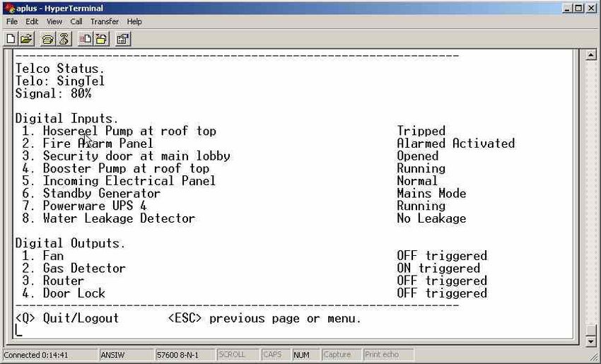
Linkwise Technology                                                                  Aplus Messenger User Manual

Contents

Chapter 1        Package Contents ........................................................................................2
Chapter 2        Safe Use of equipment.................................................................................3
Chapter 3        Interfacing to Equipment ...........................................................................8
Chapter 4        Software Configuration ............................................................................10
Chapter 5        System Operation ......................................................................................17
Chapter 6        Remote Command.....................................................................................19
Chapter 7        Specifications .............................................................................................22

Chapter 1 Package Contents

Please make sure you have the items, shown in figure 1-1, for the installation of Aplus Messenger.
Contact your distributor if any items are missing. The actual items in your package may vary in
appearance from the ones illustrated.

         1

                                                         9
                                                                                                  10

                                                                                         8
 3

                      4
                                                                                                                        2
                               12
                  11

     6                                7
                                                                   5

Figure 1.1

                                                             2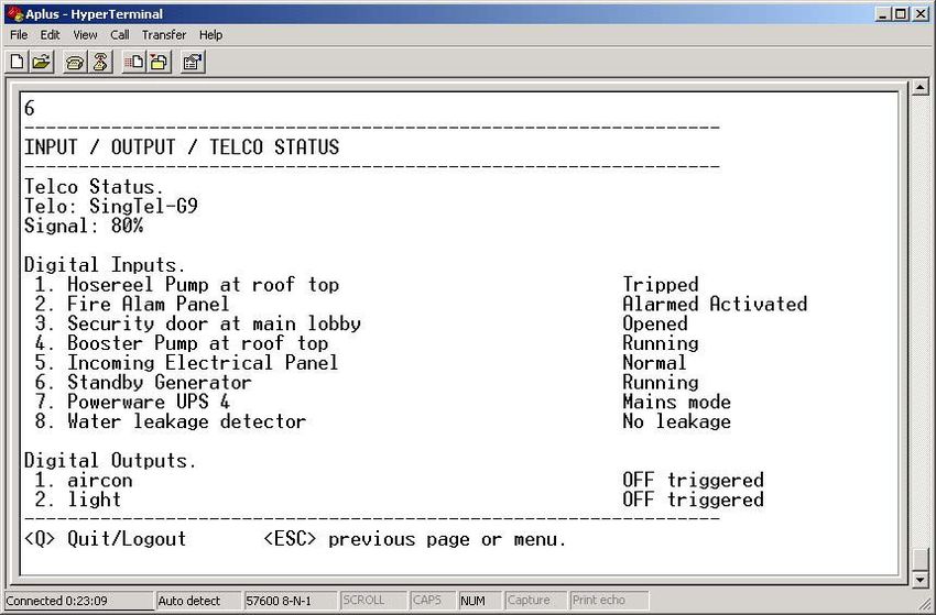
Linkwise Technology                                                      Aplus Messenger User Manual

Contents included in this purchase.
  Item                Descriptions                             Model / Part No           Quantity
      1      Aplus Messenger                                     AM900/AM910                  1
      2      Aplus Mounting Plate                                    S600-900                 1
      3      10way screw terminal block                              A120-10                  1
      4      6way screw terminal block                                A120-6                  1
      5      3mm Screw                                               S600-003                 2
      6      Power Adaptor                                           1PA1215                  1
      7      Adhesive Rubber Feet                                   R400-493                  4
      8      Screw Driver                                            S600-200                 1
      9      Serial Cable                                            100-2209                 1
      10     SMA Mount right angle unity gain antenna                AntR/A                   1
      11     User Manual in CD-ROM                                   A400-02                  1
      12     Warranty Card                                           A400-01                  1

 !         Chapter 2 Safe Use of equipment
           The following section contains important operating and maintenance (servicing) instructions.
           Please read it carefully.

       2.1 WARNINGS
2.1.1 TO REDUCE THE RISK OF ELECTRIC SHOCK:

     • DO NOT REMOVE THE COVER (OR BACK) OF THIS EQUIPMENT. THERE
       ARE NO USER-SERVICEABLE PARTS INSIDE. REFER SERVICING TO
       QUALIFIED SERVICE PERSONNEL.
     • DO NOT EXPOSE THIS EQUIPMENT TO RAIN OR MOISTURE

2.1.2 TO REDUCE THE RISK OF ELECTRIC SHOCK AND ELECTROMAGNETIC
      INTERFERENCE, USE ONLY RECOMMENDED ACCESSORIES.

                                                    3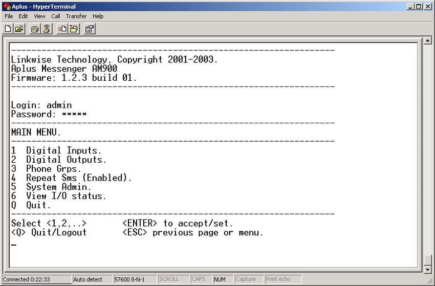
Linkwise Technology                                                      Aplus Messenger User Manual

       2.2 NOTE
The serial number of this equipment is shown on the back of the product. You should record the number
and other vital information here and retain this book as a permanent record of your purchase.

Model No.:

Serial No.:

Date of Purchase:

Dealer Purchased from:

Dealer Address:

Dealer Telephone No.:

       2.3     IMPORTANT SAFETY INSTRUCTIONS

In these safety instructions, the word ”equipment” refers to the Aplus Messenger and all its accessories.

Read Instructions – Read all the safety and operating instructions before operating the equipment.

   2.3.1 Retain Instructions – Save the safety and operating instructions for future reference.

   2.3.2 Heed Warnings – Heed all warnings on the equipment and in the operating instructions.

   2.3.3 Follow Instructions – Follow all operating and maintenance instructions.

   2.3.4 Cleaning – Unplug this equipment from the wall outlet before cleaning. Wipe the equipment
         with a clean soft cloth. If necessary, put a cloth in diluted neutral detergent and wring it well
         before wiping the equipment with it. Finally, clean the equipment with a clean dry cloth. Do
         not use benzene, thinner or other volatile liquids or pesticides as they may damage the
         product’s finish. When using chemically treated cleaning cloths, observe their precautions
         accordingly.

   2.3.5 Accessories – Use only accessories recommended in this manual. Always use specified
         connection cables. Be careful to connect devices correctly.

   2.3.6 Water and Moisture (Hazard of electric shock) – Do not use the equipment near water or in
         rainy or moist situations.

   2.3.7 Ambient Temperature – Do not put this equipment near a heater.

   2.3.8 Placing or Moving – Do not place this equipment on an unstable cart, stand, tripod, bracket or
         table. The equipment may fall and cause serious damage to itself and serious injury to others.
         An equipment and cart combination should be moved with care. Quick stops, excessive force
         and uneven surfaces may cause the equipment and cart combination to overturn.

                                                     4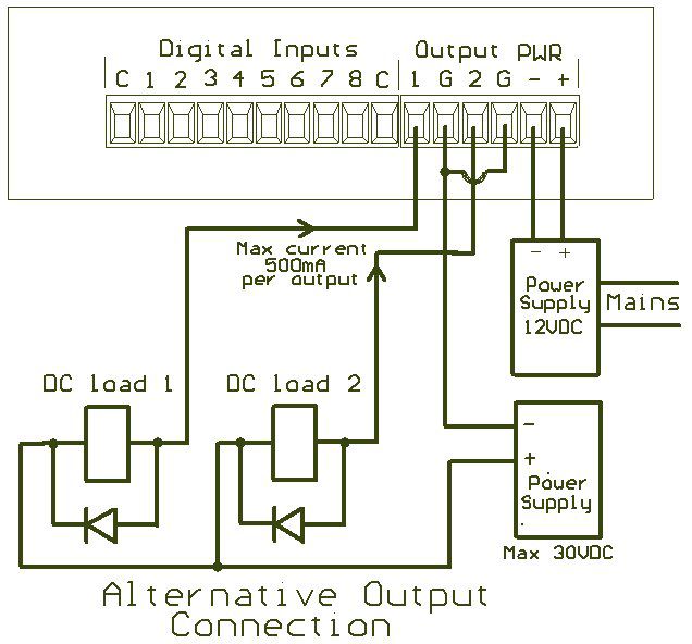
Linkwise Technology                                                       Aplus Messenger User Manual

   2.3.9 Power Sources – The AC adapter should be operated only from the type of power source
         indicated on the marking label. If you are not sure of the type of power supply to your
         premises, consult your equipment dealer or local power company.

   2.3.10 Power Cord Protection – Power cords should be routed so that they are not likely to be walked
          on, or pinched by items placed upon or against them. Pay particular attention to plugs and the
          point from which the cords exit the equipment.

   2.3.11 Outdoor Antenna Grounding – If an outside antenna is connected to the equipment, be sure
          the antenna is grounded so as to provide some protection against voltage surges and built-up
          static charges.

   2.3.12 Lightning – For added protection of this equipment during a lightning storm, or when it is left
          unattended and unused for long periods of time, disconnect it from the wall outlet and
          disconnect the antenna. This will prevent damage to the equipment due to lightning and
          power-line surges.

   2.3.13 Power Lines – An outside antenna system should not be located in the vicinity of overhead
          power lines or other electric light or power circuits, or where it can fall into such power lines
          or circuits. When installing an outside antenna system, extreme care should be taken to keep
          from touching such power lines or circuits, as contact with them might be fatal.

   2.3.14 Overloading – Do not overload wall outlets and extension cords as this can result in a risk of
          fire or electric shock.

   2.3.15 Object and Liquid Entry – Never push objects of any kind into this equipment through
          openings as they may touch dangerous voltage points or short out parts that could result in a
          fire or electric shock. Be careful not to spill liquid of any kind onto the equipment.

   2.3.16 Servicing – Do not attempt to service this equipment yourself as opening or removing covers
          may expose you to dangerous voltage or other hazards. Refer all servicing to qualified
          personnel. Opening the cover may void your warranty.

   2.3.17 Do not install the equipment in the following locations as this can cause a fire or electric
          shock:
          • Hot locations
          • Close to a fire
          • Very humid or dusty locations
          • Locations exposed to direct sunlight
          • Locations exposed to salt spray
          • Close to flammable solvents (alcohol, thinners, etc.)

   2.3.18 If any of the following occurs, immediately switch the equipment OFF, unplug it from the
           mains power supply and contact your distributor or agent:
           • The equipment emits any smoke, heat, abnormal noise, or unusual odour
           • A metal object falls into the equipment
           • The equipment is damaged in some way
           Do not continue to use the equipment as this can cause a fire or electric shock.

                                                     5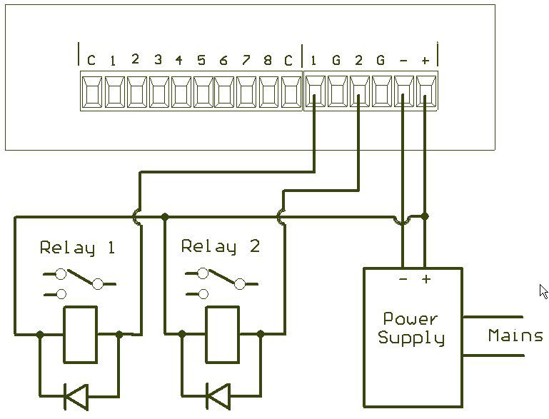
Linkwise Technology                                                       Aplus Messenger User Manual

   2.3.19 Please observe the following when using the equipment. Failure to do so can result in a fire or
          electric shock.
          • Do not use flammable sprays near the equipment.
          • Do not subject the equipment to strong impact.

Chapter 3 Hardware Installation

Congratulations on your purchase of Aplus Messenger, a feature-packed GSM wireless messaging
controller that serves wide-ranging monitoring and control application. Please read the instructions in
this User Manual carefully before installing this equipment.

This section will guide you through the installation of your Aplus Messenger. Just follow the instructions
here and you will have product installed very quickly.

Before starting installation, ensure that the unit is powered OFF and the power adapter plug disconnected
from the rear of the unit.

       3.1     Aplus Messenger Unit

             Front View                                              Back View

Step 1. Determine a suitable location for the installing of Aplus Messenger unit. In selecting a location,
        remember that you will need to connect the power adapter, connections to the equipments to be
        monitored and antenna. Follow carefully the instructions provided earlier in this manual on the
        safe use of this equipment.

Step 2. Insert a valid GSM mobile telephone SIM card into the SIM card socket slot on the rear panel of
        the Aplus Messenger.

       •   To insert the card, first eject the SIM card tray by pushing the yellow eject button. Do this
           using a small blunt tool. Example, paper clip or a Philips head screwdriver.

                                                     6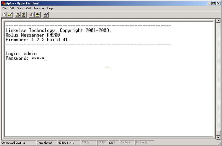
Linkwise Technology                                                        Aplus Messenger User Manual

       •   Place the SIM card on the tray. Check that the SIM card is seated fully on the tray. Insert the
           tray into the holder. Ensure correct orientation. The SIM card in the SIM tray should be facing
           downwards.
       •   Position it horizontally and slide it in with a gentle force. If you experience tightness or
           friction when attempting to insert the tray, do not force it in. Check that the SIM card is sitting
           firmly on the tray.
       •   Slide it in all the way until you feel it touching the end. About 1mm of the SIM card tray will
           remain exposed to allow for its removal.

                                                                       IMPORTANT NOTICE:
                                                           To ensure proper operation, the SIM card inbox
                                                           must be empty during the initial setup. If there
                                                           are SMS’s in the SIM card, use the mobile
                                                           phone to delete all messages in the inbox before
                                                           inserting the SIM card into Aplus Messenger.

                                                           Insert tray with SIM
                                                          card facing downwards

Step 3. Attach the antenna provided in the package onto the antenna socket on the rear panel. If an
        external antenna is required, contact your distributor for more information on external high gain
        antennae. (Warning: Do not operate Aplus Messenger without an antenna installed. It may
        damage the unit.)

Step 4. Wire the input/output connection between the equipment and Aplus Messenger using the supplied
        3.8mm pluggable screw terminals provided. See Figure 1.1 (Package Contents)

3.2    Antenna
The antenna provided is a unity gain SMA connector type. This antenna will suffice for most locations.
However, if Aplus Messenger is installed in location where signal strength is low (30% or lower) an
external high gain antenna is recommended. Contact your distributor for more information on external
high gain antennae.

3.3    Power Adapter

The power supply adapter is included in this product package. Screw the 2 wires to 6-ways pluggable
screw terminals labelled +/-. Ensure the wires are in the correct positions and polarity then plug the
adapter onto your AC wall outlet. Incorrect polarity may damage the equipment. Please ensure that the
adaptor provided is have the correct AC input voltage and frequency for your country. If the adapter is
not the correct type, contact your distributor for a replacement.

If you wish to use your own DC power supply for Aplus Messenger, its voltage/current rating should be:

               DC voltage: 12 – 30V regulated
               Current: 1.5Amps

                                                      7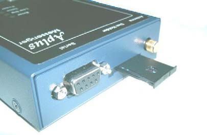
Linkwise Technology                                                    Aplus Messenger User Manual

Chapter 4 Interfacing to Equipment

                                             Figure 2 below shows how alarm inputs are wired to
                                             Aplus. Up to 8 dry contacts can be monitored
                                             simultaneously. The contacts shown are either relay
                                             contact or switches from within the equipment. Cabling
                                             distance of up to 50 meters between the equipment and
                                             Aplus is possible without causing false triggering. In noisy
                                             environment, shielded cables are recommended. Unused
                                             inputs can be left unconnected.

Figure 1 Input Interface

Interfacing to output loads

                                                                Figure 2 shows the power supply
                                                                connection to Aplus and output
                                                                connected to 2 relays. Observe the
                                                                polarity of the power supply
                                                                connection. Wrong polarity can
                                                                damage the Aplus unit. Aplus can
                                                                accept DC input from 12-30 Volts. The
                                                                relay to be driven by the output driver
                                                                of Aplus must match the supply
                                                                voltage. That is, if the DC supply
                                                                voltage is 12 volts, then the relay used
                                                                must have a coil rating of 12 volts also.
                                                                Always have a diode soldered across
                                                                the relay coil to prevent back EMF
                                                                from damaging the output drivers of
                                                                Aplus.

Figure 2 Output and power supply interface

                                                  8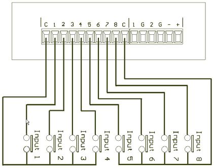
Linkwise Technology                                                  Aplus Messenger User Manual

Alternative load interfacing

                                                               Aplus is also capable of driving low
                                                               power loads directly without using
                                                               relay interface. The output driver is an
                                                               open-collector transistor; each can sink
                                                               up to 500mA of load current.
                                                               Maximum handling voltage is 30
                                                               VDC. Always connect a diode across
                                                               the load to protect the transistor from
                                                               damage due to back EMF, especially
                                                               inductive loads. Recommended diode
                                                               part number: 1N4004 or equivalent.

Figure 3 Alternative Output Connections

Aplus Messenger II (4 outputs with pusle function)

Figure 4 (Aplus Messenger II. 4 outputs with pulse function)

                                                9
Linkwise Technology Aplus Messenger User Manual
Chapter 5 Software Configuration
Configuration of messages, phone groups etc are done via the serial console port. See hardware
configuration section for detail. The connecting computer must have a RS232 serial port and have an
installed terminal emulator program running. Example: Microsoft HyperTerminal, Teraterm, etc.
Click on Start, program, accessories, communication then HyperTerminal. Click on Hyper Terminal and
the above icon will be show. Wait for it to load.
Input a name for Aplus Messenger and select an Icon. Click OK
Select the correct COM port that connects to Aplus.
10Linkwise Technology Aplus Messenger User Manual
Set the communication settings to 57600,8,N,1 (57600 bps, 8 data bits, No parity, 1 stop bit) and no flow
control.
Click OK and the login menu will appear on the PC terminal window.
Figure 3 Login Screen
Enter Login name and password. Default login/password is admin/Admin.
Login and password can be changed using the System Admin sub-menu.
If you are unable to login in or the screen show something else then the above login page. Click on the
icon to disconnect then click on to set the following:
11Linkwise Technology Aplus Messenger User Manual
Click on ASCII Setup the pop up
menu “ASCII Setup” will be as
shown. Check for the correct setting.
Click on Input Translation the pop up
menu “Host System Encoding
Method will be as shown. Check for
the correct setting.
Click on Terminal Setting the pop up
menu “Terminal Settings” will be as
shown. Check the correct setting.
After checking the above setting. Click on to connect the Aplus Messenger.
Enter Login name and password. Default login/password is admin/Admin.
Login and password can be changed using the System Admin sub-menu.
12Linkwise Technology Aplus Messenger User Manual
If the login is successful, the Main Menu page will appear.
Figure 4 Main Menu
5.1 Menu Structure
The Main Menu provides access to various settings and functions. The Menus is designed for easy
navigation with help texts along the different levels of menus and sub-menus. [ESC], [ENTER],
[Numbers] and [Q] keys provide the primary navigation between various menus and configuration
screens. The software also traps illegal entries. Alerts prompts user of an entry error.
The detailed description are as follows:-
5.2 Digital Inputs.
This menu contains a sub-menu with 2 functions choices.
1. Input description
2. Input state definition.
Input description allows the user to create meaningful description to the inputs (up to 8) to be monitored.
Each input can have up to 40 alphanumeric characters.
Input state definition is for defining the state of each input. A digital input can assume 2 states. Contact
open and contact close. Depending on the equipment to be monitored, an open or close contact will have
different meaning.
For example,
♦ Open / close ♦ Alarm / Normal ♦ On/Off ♦ Activated /Deactivated
♦ High / Low ♦ etc.
You can define whether you would like to receive the SMS alert, by leaving the input state definition
blank for either contact close or contact open. Please note that at least one contact (open or close) must
have an input state definition to receive SMS alert. If both are empty no SMS alert will be sent.
13Linkwise Technology Aplus Messenger User Manual
For example, referring to figure above, Alarm 2 has Contact opens without input state definition and
contact closes had an input state definition as Stop. When the contact for Alarm 2 closes, SMS alert will
be sent. When the contact for Alarm 2 opens, no SMS alert will be sent.
5.3 Digital Outputs
Aplus has 2** numbers of open-drain outputs for turning on and off any low voltage devices such as
relays, lights, fans, etc. Each output can sink up to 500mA, 24V loads. See hardware section. Up to 15
alphanumeric characters, (white spaces included) can be assigned to each output. (**Aplus Messenger II
has 4 digital outputs)
Operation and forward mobile phone numbers can send SMS to Aplus to On/Off the digital outputs.
5.4 Phone Groups
There are 3 classes of phone groups, each with a specific purpose to each
• Operation
• Forward
• Authorizer
Operation numbers are those that will receive alarm SMS when one or more digital inputs are activated
(open Æ close, close Æ open). Up to 6 mobile phone numbers can be assigned to the operation group.
Phone numbers of up to 20 numbers and (+) are valid formats. Example +6598989898, 90012345
Forward – This number (if assigned) will receive alarm SMS like the operation numbers. Any incoming
SMS to Aplus will also be forwarded to this number as well. This is a very useful feature where an
organization wishes to have a central logging of all activities (alarms, in-out SMS) of Aplus Messenger.
When many Aplus are deployed in the field, the usefulness becomes more evident.
14Linkwise Technology Aplus Messenger User Manual
WARNING:
Never set the forward mobile phone number to be the same as the SIM card
number in Aplus Messenger.
This will cause the device to send no-ending SMS to itself
Authorizer. Up to 2 mobile phone numbers can be assigned to this group. These numbers are authorized
to remotely query, add, edit and delete any phone group numbers in the 3 groups using SMS commands.
See remote command table for detail. The authorizer can also delete or change its number. Caution has to
be exercised. Once the authorizer removed his number, he can no longer perform any of the authorizer
functions.
5.5 Repeat SMS
This feature, when enabled will send the alarm SMS repeatedly to the operation and forward mobile
phones. The repeat interval can be set between 2-30 minutes. To cancel repeat SMS, anyone from the
operation or forward number must send a command #ACK to Aplus. Aplus, upon receiving the #ACK
command will cancel the repeat SMS alarm. If any new alarms is triggered after receipt of #ACK
command, the new alarms will be send repeatedly until a new #ACK is received.
5.6 System Admin
The admin sub-menu allows the user to Change/Edit the Device ID, Date/time, Mobile Pin, Login ID and
login Password.
Device ID – This ID gives the Aplus unit an identity in the form of a description. This information will
be sent along with the alarm SMS. It helps the recipients to more easily identify the name or location of
the installation where the alarm is triggered.
Date/Time – The internal battery backed realtime clock keeps track of the alarm time as it happens. The
date time information is also sent along with the SMS message.
Mobile pin – The user can opt to lock the SIM card to prevent unauthorized use of the SIM card. To
enable to pin lock feature, place the SIM card on any mobile phone and use the phone function to lock
the card. (Refer to the phone manufacturer user manual for instruction) On the Aplus System Admin sub
menu, supply the same lock code as you have set using the mobile phone. Place the SIM card back to
Aplus. Refer to the section on SIM card insertion for detail)
Login ID – Allow the user or system administrator the change the default ID (admin) to a different name
(up to 8 alphanumeric characters)
Login Password - Allow the user or system administrator the change the default password (Admin) to a
different name (up to 8 alphanumeric characters)
CAUTION: Record the new Login ID and password and safe keep the information for future
reference. DO NOT FORGET THIS INFORMATION. If the login ID and/or password are
forgotten, there is no way to access Aplus Menus. You have to refer to your distributor for
assistance to reset your Login ID and password to factory default.
5.7 View IO Status.
This screen allows the user to view the Input and output description and its corresponding current status.
The Telco information and signal strength is also shown on this screen. To refresh the View IO screen,
press the [ENTER] key.
15Linkwise Technology Aplus Messenger User Manual
Figure 5 IO Status from Aplus Messenger
Figure 5a IO Status from Aplus Messenger II
5.8 Quit
This option quits and logs out the Menu function. Once the user logs out, the usual login ID and
password is required to access the Menus. Always remember to logout at the end of each session to
prevent any unauthorized user to access the pages.
After completion of all the required settings, logout and disconnect power from Aplus Messenger.
Unplug the serial cable, re-apply power to re-initialize the device.
16Linkwise Technology Aplus Messenger User Manual
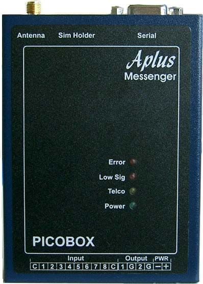
Chapter 6 System Operation
Once the hardware installation and software configuration are done, Aplus is ready for operation.
The picture below shows the top view of Aplus Messenger. Four LED indicators provide visual display
of the status during operation.
Power The green LED will lit when power is applied
to the unit
Telco Amber LED indicate the Telco network status
When blinking 0.5s on 0.5s off, Aplus is
searching for available Telco network.
When flashing 0.2s on, 08s off, Aplus is
registered to a Telco network
Low Sig If the received RF signal strength is below
30%, this red LED will light up. If SIM card
is not inserted, this LED will also lit.
Error If SIM card is not present or card is locked,
this red LED will turn on. If SIM card is
present and is locked, configure the SIM
unlock code via the serial console port (Refer
to software configuration section)
After applying power to Aplus messenger, the green Power LED and the Low Sig LED will light up.
After a few seconds the amber Telco LED will start to blink (0.5s on, 0.5s off). This rate of blinking
indicates that Aplus is searching for a valid Telco network. When it succeeds logging onto a network, the
Telco LED will flash (0.2s on, 0.8s off). If the received Telco signal strength is high enough (>30%), the
Low Sig LED will turn off.
Under normal condition, the Error LED should be off. If lighted, it indicates either:
• SIM card is not present, or
• The card is locked and the mobile pin code is not supplied or wrongly entered. Refer to software
configuration section on entering mobile pin code.
Low Sig LED with lighted, suggests that the signal strength is too low for reliable SMS operation. If this
happens, either relocate Aplus to a nearby location where the RF reception is better, or if relocating is not
possible or practical, use an external high gain antenna. Contact your distributor for a suitable
recommendation to your situation.
6.1 Alarm Triggering
An alarm event happens when any one or more digital input changes state. Aplus continuously monitor
the input for these events.
17Linkwise Technology Aplus Messenger User Manual
When an alarm event occurs, it picks up information from the configuration memory and performs the
necessary SMS actions. In such an event, all mobile phone numbers stored in the memory will be SMS
to.
The format of the message is
[Date/Time] [Device ID] [Input description] Æ [Status]
Date/Time is the time the alarm event occurs. The realtime clock within Aplus provides the time
stamping information.
Device ID – the identity assigned by the user during software configuration
The user defines input description and status during software configuration. Each digital input will have
its own unique input description name and status text.
Example of an SMS alarm message:
25/07/03 14:39> (Aplus Messenger) Fire hose reel pump at basement 2 Æ Tripped
Up to 6 mobile phones can be alerted to. This group of phone numbers is known as operation phones.
Additionally, if a forward phone number is specified, it will receive the alarm notification as well.
6.2 Repeat SMS
If enabled, when an alarm is triggered, the SMS will be sent repeated to the operation and forward group
repeated at the interval specified during software configuration. (2-30mins). To cancel repeat sending,
any mobile phone from the operation or forward must acknowledge to Aplus by replying the
acknowledge command (#ack). The command is not case sensitive. #ack, #ACK, #Ack are valid strings.
Aplus upon receipt of the acknowledge command stop sending further SMS to this alarm.
If multiple alarms are triggered, only the first one will be repeated. Subsequent alarms are sent once. This
is to prevent the recipients from unnecessary annoyance. It also saves on SMS costs.
After the alarm or alarms is acknowledged, new alarms triggered will be sent and repeated until the next
#ACK command is received by Aplus.
6.3 System Check
Authorized** mobile phone group can perform system check by sending a ?syscheck command to
Aplus, If Aplus is switched on, or working normally, it will reply to the querying mobile phone with
[Date/Time] [Device ID] [Telco name] Æ [Signal level], Example
25/07/03 14:39> (Aplus Messenger) SingTel-G9 Æ 90%
Forward mobile number, if specified will receive 2 messages from this action
1) ?syscheck from the querying mobile phone
2) reply from Aplus to the querying mobile phone.
18Linkwise Technology Aplus Messenger User Manual
** refer to remote command section to see which group is
allowed to perform a given set of query or set command.
6.4 Querying input and output status
Authorized groups can also query the status of an input or output. This is a very useful feature to
determine the present status of an input or output. The enquirer need not wait for an alarm to happen in
order to receive the given I/O status.
Refer to Remote command section of this user manual for detail.
6.5 Turning on / off devices remotely
Authorized users can send a SMS command to trigger on / off or plulse the digital output of Aplus.
Aplus, upon receiving the command, will perform the instructed action. After the on or off action is done,
it will send a reply to the querying mobile phone as an acknowledgement. There are 2 digital outputs that
can be independently controlled. (Aplus Messenger II has 4 digital outputs)
The forward group, if specified will be notified as well.
6.6 Remote Editing of mobile phone numbers
Aplus has a feature to allow users to remotely add, change or delete any mobile phone numbers in Aplus
memory.
Re-assigning of operation personnel, a change of mobile phone number is also common. Rather than
having to physically go to the installation site with a notebook computer, the authorized personnel can
perform the change from anywhere using their mobile phone. Where there are many installed sites, this
feature saves time and effort.
For details of how this can be done, refer to Remote command section in this manual.
Chapter 7 Remote Command
Aplus Messenger allows a number of important functions to be accessed and controlled remotely via
SMS by the listed and authorized mobile phones. For example, an authorized person can perform query
and changing of Operation, forward and Authorizer mobile phone numbers stored in the unit’s memory.
Operation users can query the status of Inputs/outputs and perform system checks.
The commands are easy to use and remember. Two important arguments are used in conjunction with the
action commands. [?] Is a query and [#] is a set argument.
Example: ?ROP is to a query to Read Operation Phone
#WOP is to set a Write Operation Phone
19Linkwise Technology Aplus Messenger User Manual
The three categories of users (operation, forward, authorizer) have specific rights in the use of various
remote control functions. Table 1 summarize each function and rights.
Operation
Forward
Authorizer
Action Command
Query Input status ?IP x X X
x = the Input number (1-8)
Query Output status ?OP x X X
x = the Output number (1-2)
Acknowledge an alarm #ACK X X
System Check ?SYSCHECK X X
Turn on an output #ON outname X X
outname = Output description
Turn off an output #OFF outname X X
outname = Output description
To pulse an output #PS outname X X
outname = Output description
Query Operation numbers ?ROP X
Add, Edit, Delete Operation number #WOP x num X
x = position of mobile phone number (1-6)
num = mobile phone number
Query Forward number ?RFP X
Add, Edit, Delete Forward number #WFP 1 num X
num = mobile phone number
Query Authorizer number ?RAP X
Add, Edit, Delete Authorizer number #WAP x num X
x = position of mobile phone number (1-2)
num = mobile phone number
Table 1
20Linkwise Technology Aplus Messenger User Manual
Detailed command set
Command Respond from Aplus Messenger
?IP x [Date Time] [Device ID] IP4= [Input description] → [Status]
Query an input status Eg: 23/01/2003 15:05 (Aplus Messenger) IP4= Fire Panel at zone 2 → Alarm
Example: ?IP4 activated
?OP x [Date Time] [Device ID] OP1= [Input description] → [Status]
Query an output status Eg: 23/01/2003 15:05 (Aplus Messenger) OP1= Aircon → On Triggered
Example: ?OP1
#ACK This command cancels the repeat SMS sending, no respond from Aplus
?SYSCHECK [Date Time] [Device ID] IP4= [Telco ID] → [Signal Strength]
Eg: 23/01/2003 15:05 (Aplus Messenger) STARHUB-G9 → 77%
#ON Outname [Date Time] [Device ID] [Outname] → [Action]
Example #ON Aircon Eg: 23/01/2003 15:05 (Aplus Messenger) Aircon → ON Triggered
#OFF Outname [Date Time] [Device ID] [Outname] → [Action]
Example #OFF Light Eg: 23/01/2003 15:05 (Aplus Messenger) Lifht → OFF Triggered
#PS Outname [Date Time] [Device ID] [Outname] → [Action]
Example #PS UPS Eg: 23/01/2003 15:05 (Aplus Messenger) UPS → PULSED
?ROP [Date Time] [Device ID] ROP num1,num2,num3,num4,num5,num6
Eg: 23/01/2003 15:05 (Aplus Messenger) ROP +659849403,
+601873737,0,97858965,0,0
0=no mobile phone number on that location
#WOP x num [Date Time] [Device ID] WOP x num –OK/Err-
Eg: #WOP 4 +6598989858 [Date Time] [Device ID] WOP 4 +6598989858 –OK-
Eg: #WOP 4 +659e989858 [Date Time] [Device ID] WOP 4 +659e989858–Err- (phone number has error)
?RFP [Date Time] [Device ID] RFP num
Eg: 23/01/2003 15:05 (Aplus Messenger) RFP +659849409
0=no mobile phone number on that location
#WFP 1 num [Date Time] [Device ID] RFP num –OK/Err-
Eg: #WFP 1 +659849409 Eg: 23/01/2003 15:05 (Aplus Messenger) WFP +659849409-Ok-
Eg: #WFP 1 +65984g409 Eg: 23/01/2003 15:05 (Aplus Messenger) WFP +65984g409-Err- (phone number
has error)
?RAP [Date Time] [Device ID] RAP num1,num2
Eg: 23/01/2003 15:05 (Aplus Messenger) RAP +659849403,985698982
0=no mobile phone number on that location
#WAP x num Date Time] [Device ID] WFP x num –OK/Err-
Eg: #WAP 2 +6012345678 Eg: 23/01/2003 15:05 (Aplus Messenger) WAP 2 +6012345678 –OK-
Note: If a command sent to Aplus does not match the required format or is invalid, Aplus will not
respond to the querying mobile phone and no action is taken by it. Similarly, if any unauthorized mobile
phones try to query a status or to do a set command, it will also not respond to that mobile phone.
If a Forward mobile phone is specified, all incoming SMS, either correct or invalid commands as well as
any other SMS messages from any mobile phones will be forwarded to this number for logging. This
function is in effect serves as a remote event logger.
WARNING:
Never set the forward mobile phone number to be the same as the SIM card
number in Aplus Messenger.
This will cause the device to send no-ending SMS to itself
21Linkwise Technology Aplus Messenger User Manual
Chapter 8 Specifications
Item Description
Model AM 900 / AM910
Operating Voltage 9-30VDC, 2W
No of Inputs 8 Digital protected Inputs, Volt-free / dry contact
2 current sink outputs - 500mA per output (Aplus Messenger)
No of Outputs
4 current sink outputs - 500mA per output (Aplus Messenger II)
Communication Port Serial Terminal Emulator
Dual Band GSM 900/1800 Mhz Class (2W at 900MHz) Class 1 (1W at 1800
GSM Modem
MHz)
Humidity 0-90% non-condensing
Operating Temperature 0 to 55 degree Celsius
Physical size 82 (L) x 25 (H) x 110 (D) mm
Weight 345 gm
Security Features Password protected access and phone number checks
Real Time Clock Date time with battery backup
System Health Check Remote health check feature via SMS
Indicators Power, Telco Network, Signal Low, Other error
Repeat SMS of alarms User configurable
IO Interface 3.8mm pitch pluggable screw terminal block
Remote event log Yes
22Linkwise Technology Aplus Messenger User Manual
Optional Accessories
These accessories are our effort to serve you better. You would be able to purchase it from your
distributor of our products.
External antenna
Model: Ant3db3M
External Battery 3db Dual Band External Antenna
Model: BAT7
External Battery Backup power supply unit
12V-7AH
Ideal for power failure backup
Power Rail
Model: A-194PR
19" 4 way Power Rail
End of documentation
23You can also read