DOLAR: DOUBLE LAYER ROUTING FOR BUFFERLESS MESH NETWORK-ON-CHIP
←
→
Page content transcription
If your browser does not render page correctly, please read the page content below
DoLaR: Double Layer Routing for Bufferless Mesh
                    Network-on-Chip
                      Rose George Kunthara∗ , Neethu K∗ , Rekha K James∗ , Simi Zerine Sleeba† and John Jose‡
                                     ∗
                                     Division of Electronics, School of Engineering, CUSAT, Cochin, India
     †   Dept. of Electronics & Communication Engineering, Viswajyothi College of Engineering and Technology, Muvattupuzha, India
                         ‡ Dept. of Computer Science and Engineering, Indian Institute of Technology Guwahati, India

         rosekunthara87@gmail.com, neethukuriyedam@gmail.com, rekhajames@cusat.ac.in, simi.abie@gmail.com, johnjose@iitg.ac.in

        Abstract—Network on Chip (NoC) is embraced as an intercon-            that bufferless deflection router performance surpasses VC
     nect solution for the design of large tiled chip multiprocessors         based NoC [4]. The flits which are not able to acquire desired
     (TCMP). Bufferless NoC router is a promising approach due to             output port in bufferless routers will be deflected through
     its simple router design, energy and hardware efficiency. NoC,
     which rely on underlying network architecture, is characterized          an available output port causing routing inefficiency as some
     by performance measures like latency, deflection rate, throughput         of the flits may have to traverse across non-minimal routes.
     and power. In this paper, we come up with DoLaR architecture             BLESS (BufferLESS) [4] and CHIPPER (CHeap-Interconnect
     to raise performance of standard bufferless 2D mesh NoC by               Partially PErmuting Router) [5] are two major bufferless
     stacking two similar layers of 8x8 meshes one above the other.           routers which employ deflection routing.
     DoLaR employs standard 5-port bufferless router architecture
     and the unused ports of edge routers are utilized to make vertical          We propose DoLaR, a new design based on CHIPPER,
     interconnections between the layers. Simulation results show that        where two identical layers of 2D mesh network are placed one
     our proposed design surpasses existing state-of-the-art 5-port           above the other and employs 5-port CHIPPER router microar-
     2D mesh and torus bufferless router designs in terms of better           chitecture with slight modification in the routing algorithm. On
     network saturation point and minimized deflection rate, average           comparing our design against a planar 2D mesh network and
     flit latency and power consumption.
        Index Terms—Network-on-Chip, buffer-less, deflection routing,          2D torus network employing same number of routers exhibit
     flit latency                                                              better throughput, minimal latency, deflection rate, footprint
                                                                              and power dissipation while operating at the same speed as
                             I. I NTRODUCTION                                 2D design.
                                                                                 The remainder of this paper is ordered as follows: An
        The recent developments in IC technology have led to                  outline about the related work is presented in Section II
     massive growth in transistor integration due to the plunge               and Section III discusses about motivation for our proposed
     in transistor sizes to ultra-deep submicron levels. This has             design. In Section IV, details about proposed design are
     led to emergence of complex System-on-Chip (SoC) where                   given. Section V discusses about experimental methodology
     several IP (Intellectual Property) cores are interconnected by           followed. Results are given in Section VI and finally Section
     traditional point to point or shared bus intercommunication              VII concludes the paper.
     structures. Network-on-Chip (NoC) has evolved as the pre-
     ferred communication framework to deal with technology                                         II. R ELATED W ORK
     scaling related problems such as global wire delay issue                    Conventional VC routers (VCR) employ buffers at their
     and SoC integration limitations. Modular topology, built-in              input ports so that flits can stay in them till they attain
     fault tolerance, better parallelism, scalability, load handling          a productive port. Complex buffer management circuitry is
     ability and performance over traditional on-chip interconnect            required in addition to buffers, consuming significant portion
     solutions make NoC the preferred communication solution for              of on-chip power and occupying large footprint on the chip
     TCMP design [1] [2] [3].                                                 [6] [7]. This paved way for alternate low cost NoC designs
        NoC, a packet-switched network, consists of a number of               such as centralized buffer/dynamic buffer allocation [8] [9],
     processing nodes in a single chip. TCMP generally uses 2D                buffer bypassing [10] or elimination of buffers as in the case
     mesh network architecture owing to its regularity and scala-             of bufferless routing [11]. In bufferless designs, when the
     bility. Traditional Virtual Channel (VC) based NoC network               desired output link is unavailable, flits are either discarded
     uses buffers at their input ports to improve throughput and load         [12] or deflected through a freely available output link [4] [5].
     handling ability of the network. The growing power and area              All the flits that arrive at input ports of a bufferless router
     concerns linked with VC based NoC routers are overcome by                advance through one of the output ports. If more than one
     alternate design choice like bufferless NoC deflection routers.          incoming flit contends for same output link, only one of them
     For low and medium injection rates, experimental results show            will get desired output link whereas other flits which did not

      978-1-7281-1895-6/19/$31.00 2019
                                  c     IEEE                                 400

Authorized licensed use limited to: INDIAN INSTITUTE OF TECHNOLOGY GUWAHATI. Downloaded on May 11,2020 at 11:48:12 UTC from IEEE Xplore. Restrictions apply.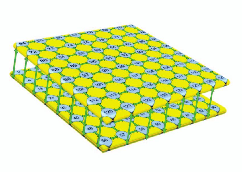
used to create areas for allotting same TSV pad for interlayer
communication that are controlled by serialization logic [18].
The average packet latency increases exponentially as the
number of switches per TSV bundle rise due to serialization
over TSV bundle.
3DPERM, a single cycle bufferless 3D router employs 9
permuter blocks to constitute 3-stage permutation network like
CHIPPER [19]. The authors show that their design has reduced
power and area overhead than a single-cycle 3D CHIPPER.
Fig. 1. Average latency versus number of processing cores for different Larger end-to-end latency and smaller network saturation point
synthetic traffic patterns in 2D mesh bufferless network owing to load computation elimination are some of the key
attributes of 3DPERM and 3D CHIPPER. 3DBUFFBLESS
[20], is an asymmetrical 3D NoC router which is buffered in
get productive links will get deflected through freely available z-dimension whereas bufferless in x and y dimensions. Their
links. Thus network saturates earlier compared to traditional proposed router merges advantages of bufferless and buffered
VC routers due to increased flit deflection rate and latency. routers to have improved routing efficiency with minimal
The baseline bufferless router, BLESS [4] utilizes a sequen- power dissipation and area.
tial port prioritization mechanism and output port selection
employs an age based flit ranking scheme. This leads to III. M OTIVATION
reduced NoC operating frequency due to rise in router’s critical The performance enhancements due to NoC design becomes
path delay. CHIPPER [5] is an improvement over BLESS a bottleneck with rise in number of processing cores as 2D
architecture which employs golden packet scheme for packet NoC has restricted floor planning options. We perform simula-
prioritization and uses parallel port allocation method. In tions on standard 2D bufferless mesh NoC, such as CHIPPER,
contrast to BLESS, CHIPPER has smaller pipeline stage delay for various synthetic traffic patterns. Figure 1 clearly depicts
or higher operating frequency but at the cost of increased flit rise in average latency as number of cores are varied for
deflection rate since the non-golden flits is pseudo-randomly uniform and neighbor traffic patterns. Communication quality
permuted. also diminishes as the network, which stretches across 2D
The performance enhancement due to developments in NoC plane, incurs more transmission delay and dissipates greater
designs is limited due to restricted floor planning alternatives dynamic power.
of 2D integrated circuits (IC). Advancements in 3D IC tech- Better routing efficiency and performance can be obtained
nology have resulted in the migration of 2D NoC based routers by stacking NoC layers. 3D NoC network has decreased
to adopt 3D NoC topology. 3D ICs comprises of several area footprint and better performance compared to 2D NoC
active layers of silicon interconnected by short links. 2D designs. Agyeman et al. compares the crossbars used in 2D
NoC networks employ horizontal links created using copper and 3D NoC router structures in terms of area and power
wires. In 3D networks, horizontal connections are made using consumption [21]. 3D NoC designs have higher number of
copper wires and Through-Silicon-Via (TSV) based links are interconnections, complex arbitration mechanism and employ
used for vertical interconnections. Better packaging density, 7-port router structure. Thus, in spite of lower packet latency
noise immunity, minimal power dissipation and improved in 3D NoC network, hardware overhead is more as 7-port
performance are some of the advantages of 3D IC technology architecture is employed for flit traversal across all three
[13] [14]. dimensions.
Li et al. proposes Hybrid 3D NoC-Bus mesh or stacked To improve the performance of 2D bufferless mesh NoC
mesh structure, which is a combination of packet-switched networks, we exploit the area and performance advantages of
network and bus structure [15]. Improved performance is 2D and 3D NoC designs in our proposed design. 2 similar
obtained by replacing standard 7-port 3D NoC router with a layers of 8x8 meshes are stacked and all routers employ 5-port
6-port hybrid NoC-Bus 3D switch, which reduces inter-layer CHIPPER microarchitecture. TSV based vertical interconnec-
distance. Better integration between NoC network and bus tions formed through unused ports of edge routers are utilized
structure is achieved by using addition arbiter for every pillar for inter-layer communication.
or vertical bus. Ciliated 3D mesh is a novel architecture that
is formed by joining several layers of IP blocks while limiting IV. P ROPOSED D ESIGN
the switches to a single layer or very few layers [16]. They The performance of any NoC network is influenced by
also analyse performance of various 3D NoC architectures to topology, routing algorithm and router microarchitecture. We
highlight superior functionality of their proposed structure. choose mesh topology for our proposed work due to its
Xu et al. assess the consequence of reducing TSV count to scalability, regular structure and short interconnection links.
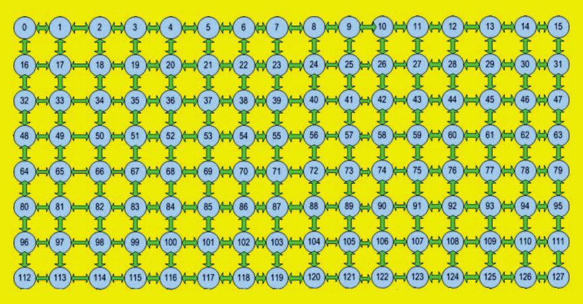
half and quarter on 3D NoC functionality [17]. Unbalanced 3D Figure 2 depicts a 128 core chip arranged as a 2D 8x16 mesh
switch distribution and varying delays for various applications network. Figure 3 shows our proposed structure, DoLaR with
are some flaws of their design. Partition islands of switches are 128 routers stacked into 2 layers, each of size 8x8. All the
2019 IEEE Region 10 Conference (TENCON 2019) 401
Authorized licensed use limited to: INDIAN INSTITUTE OF TECHNOLOGY GUWAHATI. Downloaded on May 11,2020 at 11:48:12 UTC from IEEE Xplore. Restrictions apply.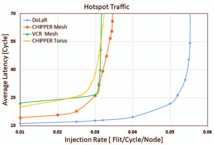
Fig. 2. 8x16 2D Mesh NoC

                                                                                     Fig. 4. Two stage router pipeline architecture of CHIPPER [5]

                                                                                Algorithm 1: Double Layer Routing algorithm
                                                                                 Input : current router, destination router
                                                                                 Output: output port

                                                                                 if (current router layer == destination router layer)
                                                                                   then
                                                                                      XY routing algorithm
                                                                                 else
                     Fig. 3. DoLaR - 2 Layer 8x8 Mesh NoC                             find hops east
                                                                                      find hops west
                                                                                      find hops north
     edge routers have an unused port in standard 5-port 2D mesh                      find hops south
     NoC network. We utilize these unused ports to form vertical                       //number of hops to destination from current router
     interconnections between the layers using TSV based links.                         via east, west, north and south port respectively
         DoLaR employs 5-port router structure of two cycle sym-                      if hops east is smallest then
                                                                                           output port = east
     metrical bufferless CHIPPER, as given in figure 4. The main
                                                                                      else if hops west is smallest then
     features of various functional units are described as follows.                        output port = west
     Input flits that progress through different modules of router                    else if hops north is smallest then
     pipeline are carried by four internal flit channels. Flits from                       output port = north
     nearby routers arrive at input port at the onset of each clock                   else
     cycle. At the end of each clock cycle, flits get preserved in                         output port = south
     corresponding pipeline registers. Our proposed design uses                       end
     Double Layer Routing algorithm, which is described in Al-                   end
     gorithm 1. When source and destination routers are in the
     same layer, static XY routing is used. For inter-layer routing,
     flits proceed to the nearest edge router that has smallest
     Manhattan distance to the destination router. In bufferless               store flits.
     routers, deadlock does not exist as cyclic dependency of                     Port allocation issues arise in bufferless routers when more
     resources cannot occur and the golden flit priority scheme in             than one flit contend for same output port, as there are no
     CHIPPER overcome livelock problem.                                        buffers to hold the flits. Permutation network employed in
         The incoming flits have to first pass through ejection and            CHIPPER is being used in our design. The deflected flits are
     injection unit. A flit which is destined to local core is directed        redirected through freely available output links in a highly
     to ejection port by removing it from internal flit channel.               efficient parallelizable manner using golden flit concept for
     CHIPPER supports only one ejection port and one injection                 assigning flit priority. Highest priority will obtain productive
     port per router. Injection will happen only when any one of               link and rest of the flits may or may not get desired output
     the internal flit channel is free since there are no buffers to           link depending on port conflicts and extent of contention.

     402                                           2019 IEEE Region 10 Conference (TENCON 2019)

Authorized licensed use limited to: INDIAN INSTITUTE OF TECHNOLOGY GUWAHATI. Downloaded on May 11,2020 at 11:48:12 UTC from IEEE Xplore. Restrictions apply.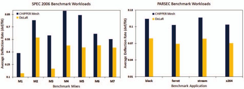
Fig. 5. Average latency comparison for different synthetic traffic patterns.
CPU2006 benchmark application suite and PARSEC bench-
mark programs [23], [24]. We use Multi2Sim simulator to
prototype a 128-core multicore system [25]. Each processing
core is assumed to have an out-of-order x86 processing unit
with 4-way set-associative, 64KB private L1 cache and 16-
way set associative, 512KB shared distributed L2 cache. Each
processing core is allocated with one of the SPEC CPU2006
application to run on it. Depending on misses per kilo in-
structions (MPKI) values found on L1 cache, we categorize
benchmark applications into Low (MKPI value less than 5),
Fig. 6. Average latency versus number of processing cores Medium (MPKI value between 5 and 25) and High (MPKI
value greater than 25). We produce 7 multiprogrammed work-
load mixes by combining various applications from benchmark
V. E XPERIMENTAL M ETHODOLOGY suite. Multithreaded workloads are run on a similar setup
We employ a cycle accurate NoC simulator Booksim 2.0 with slight alterations to produce adequate traffic for analysis
[22], that prototype traditional VC based NoC router [1]. We purpose. To simulate network operations, NoC simulator is fed
then make necessary alterations to model a two-cycle buffer- with network traffic produced by running the real workloads.
less deflection router microarchitecture described in CHIPPER
[5]. Independent routing of all the flits inside a packet is VI. R ESULTS AND A NALYSIS
achieved by attaching header information to each and every
We compare the performance of DoLaR against conven-
flit, as is the typical standard followed in bufferless routers.
tional mesh topology based VCR and standard CHIPPER for
Necessary reassembly mechanism is utilized for handling out-
mesh and torus topologies. For our analysis, we assume 16
of-order flit delivery. To represent source and destination core
VCs per input port for VC router. We use deterministic and
address in a 128-core network, we use 14-bit header field.
deadlock free XY routing algorithm for VCR, CHIPPER mesh
We employ folded torus topology for evaluation purposes to
and torus designs to evaluate performance enhancement of our
eliminate long end-around links at the expense of increasing
proposed approach.
the span of other links twofold [1]. Additional changes are
made to this baseline bufferless router simulator to prototype
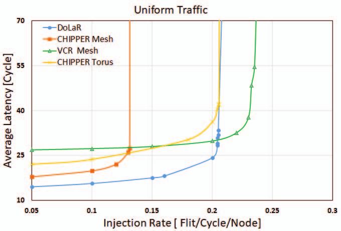
A. Effect on Average Flit Latency
our new design for conducting experimental analysis.
Flit latency is defined as the total time elapsed between
A. Synthetic Workload flit creation time at source node and flit arrival time at
We evaluate the performance of DoLaR against CHIPPER destination node, including queuing time at source core. Figure
for mesh and torus topologies of 8x16 dimensions (128 nodes). 5 shows average flit latency comparison between 8x16 2D
Average latency, deflection rate and throughput readings are mesh VCR, 8x16 2D mesh CHIPPER, 8x16 torus CHIP-
taken after adequate warm up time for different synthetic PER and our proposed design for various synthetic traffic
traffic patterns such as uniform, tornado, bit-complement, bit- patterns. DoLaR reduces average flit latency by 21%, 14%
reverse, neighbor, shuffle and hotspot by changing the injection and 21% for uniform, bitcomp and hotspot traffic respectively,
rate from zero to saturation point. compared to CHIPPER mesh. There is exponential rise in
average latency value as injection rate approaches saturation.
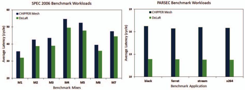
B. Real Workloads Lower and broader flit latency curve shows better router
To show the superior performance of DoLaR, we analyse performance. VCR saturate early as static XY routing used
our proposed design against baseline CHIPPER employing makes it congestion prone. DoLaR is a better option for high
mesh and torus topologies using real workloads such as SPEC network injection rate applications as it has lower latency value
2019 IEEE Region 10 Conference (TENCON 2019) 403
Authorized licensed use limited to: INDIAN INSTITUTE OF TECHNOLOGY GUWAHATI. Downloaded on May 11,2020 at 11:48:12 UTC from IEEE Xplore. Restrictions apply.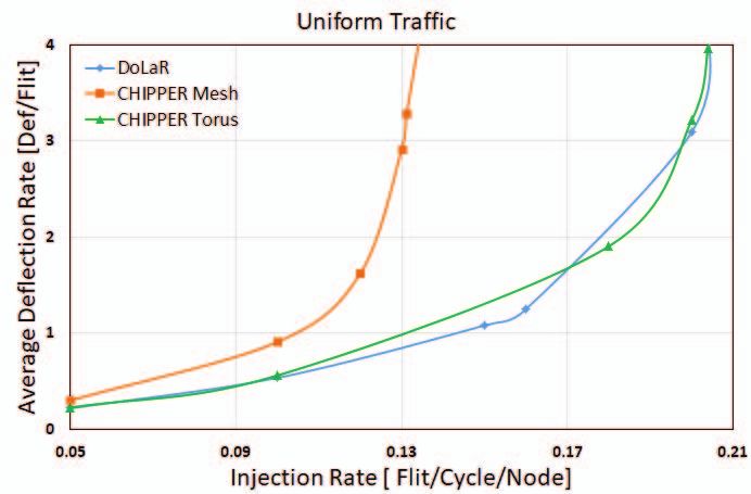
Fig. 7. Average flit deflection rate comparison for different synthetic traffic patterns.
Fig. 8. Average latency for real applications
Fig. 10. Througput comparison for different synthetic traffic patterns.
overall router area which is based on total number of routers
in NoC and per router area overhead that depends on number
of ports in each router. 5-port router architecture is generally
utilized in 2D NoC whereas 7-port structure is employed in
standard 3D NoC designs. As DoLaR design and standard
CHIPPER design uses the same 5-port router architecture,
their router area overhead remains almost comparable. The
Fig. 9. Average deflection rate for real applications
negligible router area overhead due to the modified routing
logic employed in DoLaR is inconsequential compared to
and also extends network saturation point compared to other significant gains achieved in terms of average latency and
designs under consideration. deflection rate reductions.
Figure 6 shows how average latency values get affected Wiring overhead for 2D NoC network is only due to
with scaling of number of processing cores. When compared horizontal wirings. Thus, 2D mesh of dimension 8x16 requires
with CHIPPER mesh and torus designs, DoLaR design has 232 horizontal links. 3D NoC incurs overhead due to inter-
significant drop in average latency values as number of pro- layer via footprint in addition to wiring overhead caused by
cessing cores is increased. Figure 8 depicts notable reduction horizontal and vertical links. DoLaR employs 224 horizontal
in average flit latency compared to mesh topology based links, which is twice that of 8x8 mesh NoC and extra vertical
CHIPPER for multiprogrammed and multithreaded workloads. links (28 TSV links) for interconnecting the edge routers.
Though TSV links incurs some metal and silicon area, DoLaR
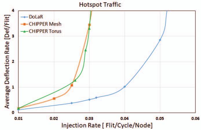
B. Effect on Average Deflection Rate has minimal footprint as two layers of 8x8 mesh are placed
Deflection rate is calculated as average number of deflec- one above the other.
tions occurring per injected flit. As injection rate rises, due to
more port contentions, deflection rate will also increase. Figure D. Effect on Throughput
7 and figure 9 clearly depict superior performance of our Throughput is defined as the amount of flits ejected from
design for synthetic and real traffic respectively. The reduction network per router per cycle. Number of physical links and
in deflection rate indicates decreased network activity thereby average hop count determine improvement in throughput for
improving dynamic power savings across links. multi-layer networks. Figure 10 depicts throughput compar-
ison between DoLaR, CHIPPER mesh and torus designs for
C. Area Overhead various synthetic traffic patterns. DoLaR has better throughput
The total area overhead in a NoC network includes router showing greater amount of sustainable traffic owing to its
overhead and wiring overhead. Router overhead comprises of reduced average hop count and more number of physical links.
404 2019 IEEE Region 10 Conference (TENCON 2019)
Authorized licensed use limited to: INDIAN INSTITUTE OF TECHNOLOGY GUWAHATI. Downloaded on May 11,2020 at 11:48:12 UTC from IEEE Xplore. Restrictions apply.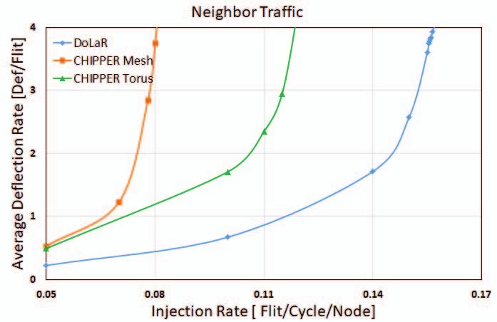
E. Effect on Router Pipeline Delay                                              [4] T. Moscibroda and O. Mutlu, “A case for bufferless routing in on-chip
                                                                                          networks,” in ISCA, pp. 196-207, 2009.
         Router delay is defined as the time taken by a flit to travel                [5] C. Fallin et al., “CHIPPER: A low complexity bufferless deflection
      from input port to output port of a router. To calculate router                     router,” in HPCA, pp. 144-155, 2011.
      pipeline latency, we implement and synthesize Verilog HDL                       [6] Y. Hoskote et al., “A 5-GHz mesh interconnect for a teraflops processor,”
                                                                                          IEEE Micro, vol. 27, no. 5, pp. 51-61, 2007.
      models of router employed in CHIPPER and DoLaR using                            [7] M. B. Taylor et al., “Evaluation of the raw microprocessor: An
      Xilinx Vivado Design Suite-HLx. As both CHIPPER and                                 exposedwire-delay architecture for ILP and streams,” in ISCA, 2004.
      DoLaR have 5-port deflection router structure, they employ                      [8] Ling. Wang, Jianwen. Zhang, Xiaoqing. Yang and Dongxin. Wen,
                                                                                          ”Router with Centralized Buffer for Network-on-Chip,” in GLSVLSI09,
      similar functional units, except for the routing logic. Since                       pp. 10-12, May 2009.
      the second stage of CHIPPER has more delay than its first                       [9] C. A. Nicopoulos, D. Park, J. Kim, N. Vijaykrishnan, M. S. Yousif and C.
      stage, router pipeline frequency of CHIPPER is determined                           R. Das, “ViChaR: A dynamic virtual channel regulator for network-on-
                                                                                          chip routers,” in Proceeding of the 9th Annual International Symposium
      by the delay of its second stage. So, pipeline frequency of                         on Microarchitecture(MICRO), pp. 333-344, 2006.
      DoLaR will be same as that of CHIPPER.                                         [10] Avinash. Kodi, Ahmed. Louri and Janet. Wang, “Design of energy-
                                                                                          efficient channel buffers with router bypassing for network-on-chips,”
      F. Effect on Dynamic Power Consumption across NoC links                             in NOCS, pp. 826-832, 2009.
                                                                                     [11] E. Nilsson et al., “Load distribution with the proximity congestion
         Power dissipation across individual routers and inter-router                     awareness in a network-on-chip,” in DATE, pp. 1126-1127, 2003.
      wire links collectively determine total NoC network power.                     [12] M. Hayenga et al., “SCARAB: A single cycle adaptive routing and
      The underlying interconnection architecture decides the net-                        bufferless network,” in MICRO, pp. 244-254, 2009.
                                                                                     [13] A. W. Topol et al., “Three-Dimensional Integrated Circuits,” in IBM J.
      works reliability in terms of power dissipation. Power con-                         Research and Development, Vol. 50, No. 4/5, 2006.
      sumption in network is proportional to packet injection rate                   [14] W. R. Davis et al., “Demystifying 3D ICS: The Pros and Cons of Going
      as it decides the amount of network activity. The power                             Vertical,” in IEEE Design and Test of Computers, Vol. 22, No. 6, pp.
                                                                                          498-510, 2005.
      dissipation across the router is same in DoLaR and 8x16                        [15] F. Li, C. Nicopoulos, T. Richardson, Y. Xie, V. Narayanan, and M.
      CHIPPER as both of them employ similar functional units                             Kandemir, “Design and management of 3D chip multiprocessors using
      in their router architecture.                                                       network-in-memory,” in Proc. Int. Symp. Comput. Archit., pp. 130141,
                                                                                          2006.
         The area and power associated with the network is studied                   [16] B. S. Feero and P. P. Pande, “Networks-on-Chip in a Three-Dimensional
      and compared using Orion [26]. The standard 65nm technol-                           Environment: A Performance Evaluation,” in IEEE Transactions on
      ogy at 1GHz operational frequency with one cycle inter-router                       Computers, pp. 32-45, 2009.
                                                                                     [17] T. Xu, P. Liljeberg, and H. Tenhunen, “A study of through silicon via
      link delay is presumed for our analysis. For both CHIPPER                           impact to 3D network-on-chip design,” in Proc. Conf. Electron.Inf. Eng.,
      and DoLaR, router area remains comparable as the same 5-port                        pp. 333-337, 2010.
      router structure is followed. DoLaR reduces dynamic power                      [18] Y. Wang, Y.-H. Han, L. Zhang, B.-Z. Fu, C. Liu, H.-W. Li, and X. Li,
                                                                                          “Economizing TSV resources in 3D Network-on-chip design,” in IEEE
      dissipation across NoC links by 32% for uniform traffic, 29%                        Trans. Very Large Scale Integration Syst., vol. 23, no. 3, pp. 493506,
      for bit-complement and 37% for hotspot traffic when compared                        Mar. 2015.
      with CHIPPER mesh design. The reduced average hop count                        [19] C. Feng, Z. Lu, A. Jantsch, and M. Zhang, “A 1-Cycle 1.25GHz
                                                                                          Bufferless Router for 3D Network-on-Chip,” in IEICE Transactions on
      and deflection rate of our proposed design is instrumental in                       Information and Systems, Volume E95.D, Issue 5, pp. 1519-1522, 2012.
      reducing the dynamic power across NoC links.                                   [20] K. Tatas, S. Savva and C. Kyriacou, ”3DBUFFBLESS: A Novel
                                                                                          Buffered-Bufferless Hybrid Router for 3D Networks-on-Chip,” in 27th
                               VII. C ONCLUSION                                           International Symposium on Power and Timing Modeling, Optimization
                                                                                          and Simulation (PATMOS 2017), 2017.
         The emergence of NoC as a preferred communication                           [21] Michael Opoku Agyeman, Ali Ahmadinia and Nader Bagherzadeh,
      framework has repressed design issues like bottleneck chal-                         “Performance and Energy Aware Inhomogeneous 3D Networks-on-
      lenges and scalability problems encountered by traditional SoC                      Chip Architecture Generation,” in IEEE Transactions on Parallel and
                                                                                          Distributed Systems, Vol.27, No.6, pp. 1756-1769, 2016.
      based architectures. DoLaR is proposed in this paper, where                    [22] Nan Jiang, Daniel U. Becker, George Michelogiannakis, James Balfour,
      two identical layers of 8x8 meshes are stacked one above                            Brian Towles, John Kim and William J. Dally. “A Detailed and Flexible
      the other using minimal number of vertical interconnections                         Cycle-Accurate Network-on-Chip Simulator,” in IEEE International
                                                                                          Symposium on Performance Analysis of Systems and Software, 2013.
      along the edge routers. Area and performance benefits of 2D                    [23] “SPEC2006 CPU benchmark suite,” http://www.spec.org.
      and 3D architectures are put to use in our design approach                     [24] C.Bienia et al., “The parsec benchmark suite: characterization and
      with minimum TSV based vertical connections and utilizing                           architectural implications,” in PACT, pp. 7281, 2008.
                                                                                     [25] R. Ubal et al., “Multi2sim: A simulation framework to evaluate
      standard 5-port bufferless router architecture. Experimental                        multicore-multithreaded processors,” in SBAC-PAD, pp. 62-68, 2007.
      outcomes indicate that DoLaR achieves better network per-                      [26] A. B. Kahng et al., “ORION 2.0: A Fast and Accurate NoC Power
      formance when compared with 2D CHIPPER mesh and torus                               and Area Model for Early-Stage Design Space Exploration,” in Design,
                                                                                          Automation Test in Europe (DATE), pp. 423-428, 2009.
      designs.
                                   R EFERENCES
       [1] W. Dally and B. Towles, Principles and Practices of Interconnection
           Networks, Morgan Kaufmann, USA, 2004.
       [2] William Dally, “Route packets, not wires: On-Chip interconnection
           networks”, in Design Automation Conference (DAC-01), pages 684-689,
           New York, ACM Press, June 2001.
       [3] W. Dally, “Virtual-channel flow control,” IEEE Transactions on Parallel
           and Distributed Systems, vol. 3, no. 2, pp. 194-205, 1992.

                                                 2019 IEEE Region 10 Conference (TENCON 2019)                                                                 405

Authorized licensed use limited to: INDIAN INSTITUTE OF TECHNOLOGY GUWAHATI. Downloaded on May 11,2020 at 11:48:12 UTC from IEEE Xplore. Restrictions apply.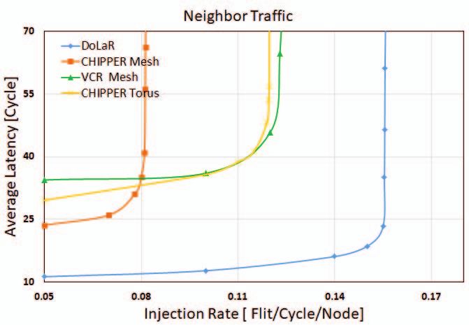
You can also read