Design Brochure Network Rail Station Footbridge - N.W.R BRIDGES
←
→
Page content transcription
If your browser does not render page correctly, please read the page content below
Network Rail
          Station Footbridge

          Design Brochure
          April, 2019

GES                            PRELIMINAR

                               AC       0

D ANALYSIS MODEL RENDERS
                                18-33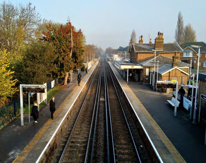
To deliver and maintain
                                                  world class rail assets that
                                                  provide the heartbeat                                          Station type
                                                  for our nation’s transport
                                                  system.

                                                  Our vision applies across our built environment and is
                                                  guided by our responsibility to deliver through good
                                                  design a safe and reliable railway to the millions of people
                                                  who use it daily. We want our assets to be sustainable and
                                                  our vision should enable us to deliver outstanding value
                                                  for taxpayers and customers. Our heartbeat is driven by our
                                                  ambition to strengthen our existing network and estate.

                                                       Our Principles of Good Design:

r and maintain                                                  Identity

ss rail assets that                                             Community focused
he heartbeat                                                    Inclusive
ation’s transport
                                                                Enhancing heritage

                                                                Connected                                        •   Local stations              This bridge design provides a new standard footbridge, which can be used in many stations
                                                                                                                                                 across the network. It is aimed primarily at smaller local and commuter stations, as major
                                                                                                                 •   Commuter stations           stations will likely have a wider range of challenges with specific needs to address.
es across our built environment and is                           Contextual
 sponsibility to deliver through good design                                                                     •   2 or 4 platform stations    This bridge is suitable for spans of up to 20m, although multiple spans are possible, such as
 e railway to the millions of people who use                                                                     •   UK wide locations           in 4 platform stations. Stairs and lifts are provided at all platforms and comply with relevant
 our assets to be sustainable and our vision                    Innovative                                                                       accessibility regulations. The bridge can be used in stations with or without OHLE. The
s to deliver outstanding value for taxpayers                                                                     •   Urban and rural locations   bridge is designed to be adaptable to suit the parameters and requirements of specific
Our heartbea t is driven by our ambition to                                                                                                      stations, maximising its potential use. A range of materials are available for cladding so that
existing network and estate.                                    Collaborative                                    •   Adaptable to context        the bridge can respond to local context.

      Network Rail - Station Footbridge Design 2019                                                                                                                                                                                          3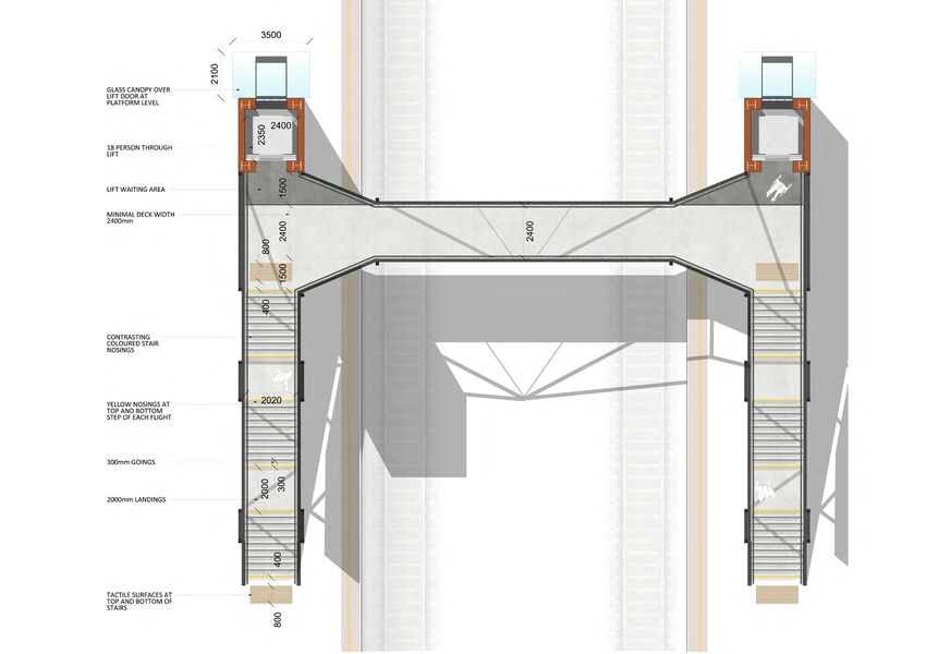
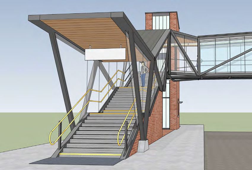
Bridge Design

             Entry                              Corner/undercroft          Link piece                      Linchpin/plinth
             • Open and Inviting                •   Corners tapered        • Continuity of light           • Visual/material
             • Simple and legible               •   Maximised visibility     triangulated structural         counterpoint/anchor to
               expression                       •   Ease of movement         expression from platform to     bridge
             • Entrance structure given         •   Undercroft open and      platform.                     • Vertical proportions
               primacy                              inviting               • Anchored by brick plinth        expressed
             • Motor room suppressed                                         and lift tower.               • Local landmark potential
             • Maximised visibility                                        • Highly legible                • Context sensitive/
                                                                                                             adaptable expression

                                                                                                                                        Vision                                       Design Criteria

                                                                                                                                        •   To establish a high standard, design     •   Be elegant and delightful
                                                                                                                                            led approach to railway infrastructure   •   Be user friendly and accessible to all
                                                                                                                                                                                         users
                                                                                                                                        •   To establish a legible NR design         •   Be suitable for construction
                                                                                                                                            identity through standardised                and maintenance in the railway
                                                                                                                                            elements, materials, detailing and           environment
                                                                                                                                            graphic language                         •   Be cost effective and sustainable
                                                                                                                                                                                         (whole life cost)
                                                                                                                                                                                     •   Reflect a commitment to a high quality
                                                                                                                                                                                         of industrial design

Network Rail - Station Footbridge Design 2019                                                                                                                                                                                     5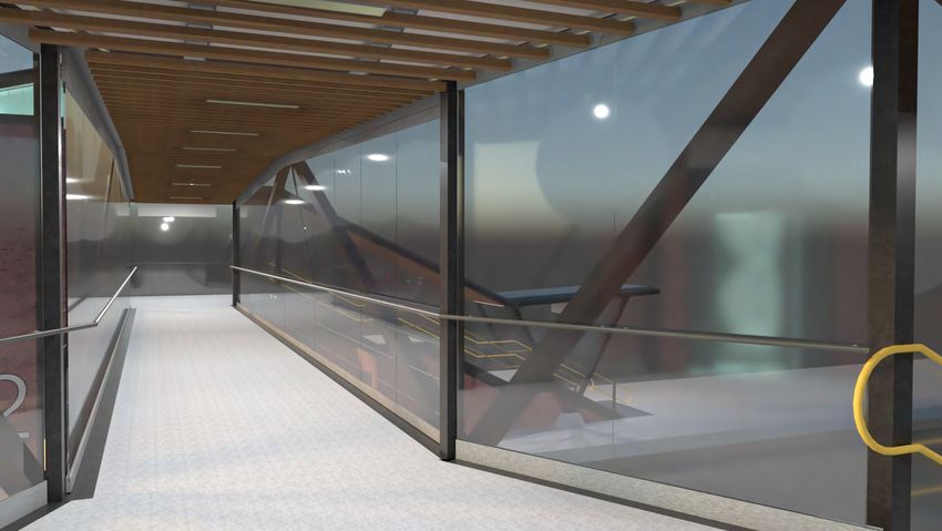
Elevations

  Elevation, External side                      Elevation, Platform side

  Elevation, Front                              Elevation, Rear

Network Rail - Station Footbridge Design 2019                              7
Plan
              Improving accessibility
              and pedestrian movement
              with tapered deck.
              A key consideration in the design of the
              generic footbridge was the orientation
              of the main components of the stair, lift,
              and deck. The stair and lift are set back
              from the deck to allow landing spaces,
              and the connection between the landings
              and deck is tapered to allow for a more
              generous space at these key points.

              The tapered deck provides more space
              at the conflict points, at the points where
              pedestrians change direction or speed,
              improving the flow of pedestrians at peak
              times.

              The lift shaft is immediately apparent
              when traversing the deck, as it is not
              hidden behind a corner, and the fully
              glazed walls as well as lighting and
              signage indicate its location.

              Lifts, stairs and landings are compliant
              with all relevant accessibility standards.

Network Rail - Station Footbridge Design 2019               9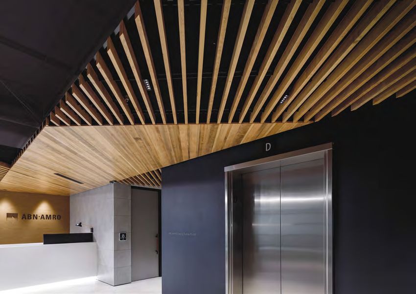
Section                                                      Glazing
                                                                                  Fully glazed for maximum visibility
                                                                                  The standard bridge design is fully enclosed, with full height
                                                                                  glazing to the stairs and deck. This makes the structure
                                                                                  appear much lighter, and reduces the impact of what can be
                                                                                  a large structure within existing station contexts.

                                                                                  Glazing provides good views out to the station and along
                                                                                  the tracks, and provides protection for inclement weather.
                                                                                  Ventilation above the ceiling helps keep the bridge cool in
                                                                                  hot weather.
ILLUMINATED
LIFT SHAFT
                                                                                  Fixed glazing on the stairs and the tapers is supported by
                                                                                  head and base tracks, with only a silicon joint at the vertical
                                                                                  junctions of the panels.

GLASS CANOPY
OVER LIFT DOOR
AT PLATFORM
LEVEL

18 PERSON
THROUGH LIFT

                 Removal of platform columns
                 The structure of the bridge has been designed so that lift
                 shaft and the stair structure form an arch, off which the deck
                 structure can be supported. This frees up platform space under
                 the bridge where columns would ordinarily be found. The lift
                 motor room is concealed under the stair structure.

   Network Rail - Station Footbridge Design 2019                                                                                                    11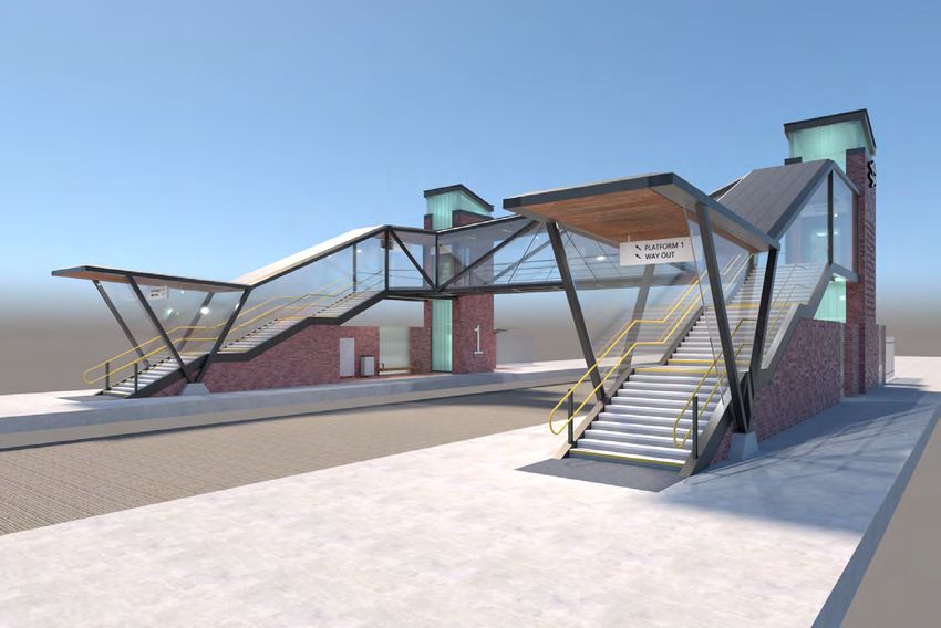
• Reduced lead times – the added conveni
• Fast quotations – no exacting site measu
Our patented fitting system allows continu
patented system
Austratus makes it easy to achieve brilliant
Austratus offers so much more than head-
ceiling. It can also be screwed directly onto
are available within relatively short time
your project moving. Even coloured was
off-the-shelf system reduces lead times
and convenience
Fit-out companies, builders and architects
timber to be simply and easily clipped into
just the square meterage of your ceiling,
of the Austratus
The simplicity
and ceilings.
Openable Glazing Ceilings - deck
Profiles Combine profiles to create
Aids cleaning over the tracks
Over the tracks, the glazing must be able to be cleaned for the
available unique architectural features
inside. Along the length of the deck, the glazing panels are
hinged so they can be opened and cleaned from the inside. Austratus comes in various sizes of All Austratus profiles are interchangeable and can be spaced at custom intervals, allowing you to control t
The openeable glazing has hinges and locks integrated into
pre-finished Fin, Flat or Fin Combo landscape of your design. Add depth and dimension with endless combinations at your fingertips. You can
the head and base channels, so no vertical frames are required. Fully openable
This is as you would see on the doors of a glazed shopfront. profiles. All Austratus
glazed panel fin profiles creative and as varied as you wish – the only limit is your imagination. Below are some standard combinat
are interchangeable. See below for examples for inspiration. We can’t wait to see what other exciting combinations are created.
Tensile steel wires are fitted to the structure outside the
profile codes and sizes.
glazing. These act as a fall protection system for operatives
who are required to clean the glass.
Tensile steel wires
fixed between
structure outside
glazing
Combination #0001
Feature lighting above slats
Combination: Fin 90 x 30mm, Fin 60 x 30mm, Fin 40 x 30mm, Fin 60 x 30mm, Fin 90 x 30mm.
Fin 90 x 30mm Fin 60 x 30mm Fin 40 x 30mm
Slat profile
Combination #0002
Installation made easy – four simple steps
Timber slats are suspended below
Step 1.
Combination: Fin 60 x 30mm, Fin 40 x Step
30mm,2.Fin 60 x 30mm, Fin 40 x 30mm. the structure as in the diagram to
Simply fix your L-shaped trim to the walls Place rails up to 600mm apart
as a level border. the left. services and lighting run in
the space between the timber slats
and the structure.
V-Fin Flat Panel
Suspended ceiling
60 x 30mm 90 x 18mm Lighting is integrated within and
Combination #0003 behind the slats, so there are no
NOW protruding objects below the plane
AVAILABLE IN
Direct fix to ceiling
Need
of the help
ceiling.
ALUMINIUM making your
Step 3. Services
decision? are easily accessed through
Step 4.
Place the plastic clips onto the battens approximately Now you’re ready to start inserting your timber lengths. the slats, or by removing slats
600mm apart. The clips slide for minor adjustments. Simply push the timber up, clicking the clips into the rails.
Combination: Fin 90 x 30mm, Fin 40 x 30mm, Fin 40 x 30mm, Fin 40 x 30mm, Fin 90 where
x Contact
30mm. necessary. Individual slats
your Austratus representative
to discuss your exact project needs.
can be replaced if they become
damaged.
You can also order an Austratus Product
Sample Kit if you wish to see physical
samples of the product before making
your decision.
For more detailed installation information
10 and videos on walls, screens and ceilings,
visit austratus.com.au
Please note: There are specific weight limits that apply to the Austratus Ceiling System. Please see the installation guide for details. 15
Network Rail - Station Footbridge Design 2019 13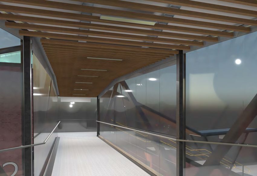
profiles. All Austratus fin profiles
are interchangeable. See below for examples for inspiration. We can’t wait to see what other exciting combinations are created.
profile codes and sizes.
Combination #0001
Combination: Fin 90 x 30mm, Fin 60 x 30mm, Fin 40 x 30mm, Fin 60 x 30mm, Fin 90 x 30mm.
Ceilings - stairway Fin 90 x 30mm Fin 60 x 30mm Fin 40 x 30mm
Combination #0002
Lighting
At the stairway entrance, the profile
of the timber ceiling will change
Combination: Fin 60 x 30mm, Fin 40 x 30mm, Fin 60 x 30mm, Fin 40 x 30mm.
to become a continuous flat soffit,
rather than an open slat ceiling.
Feature ‘wash’ lighting to
ceiling. Aids directionality.
V-Fin Flat Panel This provides a solid finish for the
60 x 30mm 90 x 18mm important entrance where the roof Apollo Razor slimline LED
is turned upwards. lighting
Combination #0003 Highlight
NOW wayfinding signage.
AVAILABLE IN The warm timber material creates a
ALUMINIUM visible. open and inviting entrance
to the bridge.
Combination: Fin 90 x 30mm, Fin 40 x 30mm, Fin 40 x 30mm, Fin 40 x 30mm, Fin 90 x 30mm. Highlight lift canopy
Illuminated lift shaft acts
as ‘lantern’. Movement
of lift car seen as shadow
10
within shaft.
Highlight seating
“It was a pleasure dealing with the Austratus team – from
estimating to delivery -they helped us all the way, which made a
complex project just that little bit easier. Their installation system
was refreshingly easy to work with and adapt for the specific
project. The fact that they were able to meet all the architects’
requirements regarding the finishes, whilst delivering the materials Ceiling downlights
to meet the program would definitely make me want to recommend Apollo Vogel LED lighting
them as an alternative to any specified ceiling system on future
projects. I look forward to doing more projects with Austratus.”
Uniform lighting levels
Drago Bozic, Parsh Power Interiors NSW Pty Ltd to floor surfaces
Ambient ground lighting
to lift entrance
11
Safe uniform lighting Ambient lighting to undercroft
level to stairs differentiates space from general
Platform use
Network Rail - Station Footbridge Design 2019 15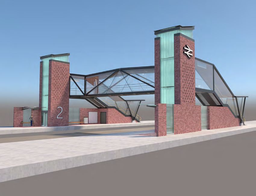
Lift shaft                                                                                British rail ‘double arrow’ logo on lift shaft

             lighting
                                                Illuminated lift shafts improve visibility of lift
                                                location. Movement of lift car evident inside shaft.   totem, improving visibility of station from afar.

                                                Apollo Alya 4 LED lighting

Network Rail - Station Footbridge Design 2019                                                                                                              17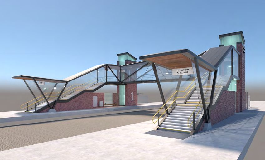
Lift tower and plinth

        Brick                                              Local stone                                        Corten                                      Metal Cladding

        A base material suitable for                      Can be used to integrate with                      A striking, robust material                  Available in a range of
        many station contexts                             local vernacular                                   Corten is a striking modern material which
                                                                                                                                                          colours and forms
                                                                                                             has a bold yet refined character. It is
        The base option uses brick to clad the lift       In stations or regions which have a strong                                                      Metal cladding can come in a range of finishes
                                                                                                             extremely robust and requires little or no
        shaft and stair plinth. Brick is widely used in   heritage of a particular material, this material                                                and colours to suit local requirements. Metal
                                                                                                             maintenance once installed. Its industrial
        stations across the country and is a material     can be used as the footbridge cladding. This                                                    cladding can be installed quickly and easily
                                                                                                             feel may be well suited to certain railway
        which is widely understood and available in       might be of particular relevance in heritage                                                    where space and/or time are limited.
                                                                                                             environments.
        most locations. The choice of brick type and      stations, or if there are planning conditions
        colours can be tailored to suit local station     which must be met.
        environments.

Network Rail - Station Footbridge Design 2019                                                                                                                                                              19
Lift tower ‘Lantern’ Undercroft
Lift shaft cladding
As shown in the previous page, the cladding of the lift
Illuminated lift shaft
shaft can be tailored to suit local station context. However,
increases visibility of lift
the structure of the lift shaft behind this cladding remains
constant, as shown in the details to the right, where the
internal steel shaft remains a standard element, and
claddings of different types and thickesses may be applied Service ducts integrated
on top. into structure
Canopy over lift
At the front and back of the shaft, a frosted glass strip waiting area
made of structural glass channels allows the shaft to be
illuminated to improve visibility of the lift. as the car moves
up and down with the shaft, its silhouette will be visible
against the illumination. Large platform numbering
The illumination of the lift shaft acts as a ‘lantern’ which can
be seen form the areas surrounding the station. This acts
to advertise the station’s presence to passengers, and can
become a focal point for the local area.
Integrated seating Station information
K-60 Exterior Non-Thermal
40
Single Glaze Details (cont.)
page
SHIM, BACKER ROD FASTENER WITH RUBBER SHIM, BACKER ROD
FASTENER WITH RUBBER AND SILICONE SEALANT WASHER INSTALLED ON AND SILICONE SEALANT
Usable platform space
WASHER INSTALLED ON
12" TO 18" CENTERS 12" TO 18" CENTERS (TYP.) (N.B. TGP)
980-1 VINYL INSERT
K-60 Exterior Non-Thermal Single Glaze Details
.25" [6] .25" [6]
980WA FRAME FRAME P.N. 980WA
USED AT JAMB
The space gained under the platform by
2.17" [55]
2.17" [55]
.79" [20] .79" [20] 980-1 VINYL INSERT
the elimination of columns can be used
for station facilities. In this example,
SILICONE SEALANT
FLANGE PLANK
2" TO AS REQUIRED seating and station information
FLANGE PLANK
2" TO AS REQUIRED boards are located in this covered
41-044 GLASS SHIM area. The materials used in the lift shaft
SILICONE SEALANT
are reflected in the materials of the
SILICONE SEALANT
2.36" [60]
contents
3.35" [85]
undercroft, unifying the platform spaces
2.36" [60] K-60 SERIES GLASS below the bridge.
K-60 SERIES GLASS
4
This treatment is extended to the
section
3.35" [85]
entrance of the lift shaft, where
a supporting wall matching the
undercroft is used to provide cover
10|13
and waiting benches adjacent to the
date
entrance to the lift.
STANDARD SINGLE GLAZING STAGGERED SINGLE GLAZING
800.426.0279 tgpamerica.com
Network Rail - Station Footbridge Design 2019 21Structure Structure external
Openable glass panels
Slim floor plate with
integrated services
ADAPTABILITY Handrail fixed to glass
FULL 3D VIEW 01 FULL 3D VIEW
Notes:
STRUCTURAL EXPRESSION
1. DO NOT SCALE FROM THIS DR
2. ALL DIMENSIONS ARE IN MILLIM
3. ALL HEIGHTS ARE IN METRES A
DATUM U.N.O.
4. THIS DRAWING IS TO BE READ
WITH ALL RELEVANT ARCHITE
DRAWINGS AND SPECIFICATIO
Structural approach
The structure of the main span is a modern
variant of a traditional structure often found CONNECTION DETAIL
in the railway environment – a steelwork
truss. The use of the full depth of the
enclosure enables the structural members
to be lightweight and elegant. The theme
of exposed structure continues down the
staircases, with the stringers in full view.
FULL 3D VIEW 01
PLINTH FULL 3D VIEW 03
02 FULL 3D VIEW
Network Rail - Station Footbridge Design 2019 23Site constructability Integrated services
The visual importance of the lift tower is reflected in its structural
importance. It is required to be in place to support the staircase stringers,
and these in turn are required to support the main span. This dictates Services concealed with
the sequence, with the final elements of the assembled trusses being structural elements
lowered onto supports, all elements having been fabricated to standard
steelwork tolerances. The location of service runs has been
designed in parallel with the structural design
to provide concealed service routes. Three
hollow steel members on the underside of the
deck provide space for cable runs across the
bridge.
Rainwater pipes are concealed within the
lift shaft, and underneath the diagonal steel
member at the stair entrance.
Refer to drawings for further details of service
integration.
Example showing bridge lifted in to place with crane
3. Bridge craned into place
2. Stairway lowered into place
4. Glazing installed
1. Lift towers and plinth constructed
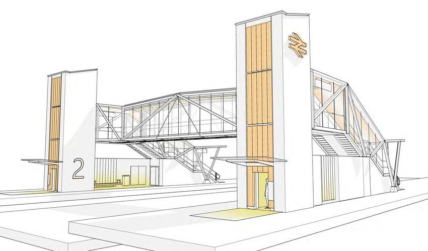
Network Rail - Station Footbridge Design 2019 Power cables Rainwater run 25Ewell West Station - Proposed Facing North Network Rail - Station Footbridge Design 2019 27
Ewell West Station - Proposed

Facing South

Network Rail - Station Footbridge Design 2019   29
Variations                             Multiple platforms
                                                                     Adaptable to multiple platform
                                                                     stations
             • Four platform station                                 The bridge has been designed as a ‘kit of parts’
                                                                     of stair, lift, and deck pieces. The configuration

             • Alternative directions                                of these can be adjusted so that the bridge can
                                                                     be extended across further platforms, or to have
                                                                     direct access from a station building at high
                                                                     level.
             • Open bridge                                           The adaptability of the bridge means that an
                                                                     assessment of particular station needs may
                                                                     result in different configurations of components.

                                                Interior deck view

Network Rail - Station Footbridge Design 2019                                                                             31
Multiple platforms Network Rail - Station Footbridge Design 2019 33
Directional variation

             Alternative directions
                                                The direction of the stair and lift can be
                                                reversed if required, and stairs on one
                                                platform do not have to match the direction
                                                of the other. This may be desirable in certain
                                                station environments where there are station
                                                entrances in different locations on each
                                                platform.

                                                An assessment of the entrances and exits, and
                                                the predominant direction of travel at the
                                                station will determine the best configuration
                                                of direction for the bridge.

Network Rail - Station Footbridge Design 2019                                                    35
Uncovered bridge which form a coherent family within the lowered by 1.5m.
bridge ‘kit of parts’.
Open Bridge
Whilst it is desirable in many instances to Glazed balustrades are provided at 1200mm
provide cover to the footbridge, there are Lift and stair structures remain constant in high to the stairs, rising to w over the tracks.
certain situations where a bridge may need both the covered and uncovered bridges, Cantilevered vertical support posts restrain
to be uncovered. The bridge design can but the deck structure is designed a simple the glazing as it cannot be restrained by a
be accommodated to suit this with a few beam bridge rather than a truss. However, roof structure. Lighting within the posts
changes. The materials and language of the due to reduced profile of the roofless deck, provides a uniform light level to the deck.
bridge are consistent across both bridges, the height of the lift towers have been
Elevation, External side Elevation, Platform side
Elevation, Front Elevation, Rear
Network Rail - Station Footbridge Design 2019 37Open Bridge 3D View, Front 3D View, Stairs 3D View, Rear 3D View, Deck Network Rail - Station Footbridge Design 2019 39
Structure
Notes:
1. DO NOT SCALE FROM THIS DRAWING.
3 4 2. ALL DIMENSIONS ARE IN MILLIMETRES U.N.O.
3. ALL HEIGHTS ARE IN METRES ABOVE ORDNANCE
DATUM U.N.O.
4. THIS DRAWING IS TO BE READ IN CONJUNCTION
450 450 WITH ALL RELEVANT ARCHITECTS AND ENGINEERS
DRAWINGS AND SPECIFICATIONS.
Structural approach
LEVEL 01
15
15
15mm THK TOP PLATE 15mm THK TOP PLATE 15mm THK TOP PLATE 15mm THK TOP PLATE 15mm THK TOP PLATE
15mm THK VERTICAL PLATE 15mm THK VERTICAL PLATE
215
215
215
215
20
20
150
150
20mm THK BOTTOM PLATE 20mm THK BOTTOM PLATE
20
20
The visual intention of the bridge is to create 20mm THK BOTTOM PLATE
20mm THK BOTTOM PLATE
20mm THK BOTTOM PLATE
20mm THK BOTTOM PLATE
as slender a structure as possible, emphasised 15
150x150x6.3 SHS
585 15 15
150x150x6.3 SHS
585 15
with the use of glass parapets. The bridge deck 600 1200 600
is therefore a pre-fabricated sealed box-girder. C
SECTION C Option 2
1 : 10
To keep the depth to a minimum, 400mm, 3 4
the full width of the deck is used structurally.
The 2.4mm wide section, 20m long, can be
450 450
LEVEL 01
pre-fabricated off-site and delivered to the
15mm THK TOP PLATE 15mm THK TOP PLATE 15mm THK TOP PLATE
15mm THK VERTICAL PLATE 15mm THK VERTICAL PLATE
site assembly yard. If transport is feasible, the
splayed ends of the deck should be included 20mm THK BOTTOM PLATE
20mm THK BOTTOM PLATE
20mm THK BOTTOM PLATE
15mm THK VERTICAL PLATE
as part of the pre-assembly, but if not, these 15
150x150x6.3 SHS
585 15 15
150x150x6.3 SHS
585 15
can be bolted on site and sealed with a site 600 1200 600
seal weld. Ducts for services are provided D
SECTION D Option 2
1 : 10
within the box girder. These at their ends FULL 3D VIEW 01 Option 2 FULL 3D VIEW
could be exposed to the elements so would B Notes:
have to be in stainless steel.
300 15
585 15
1. DO NOT SCALE FROM THIS DR
15mm THK VERTICAL PLATE 15mm THK TOP PLATE
150x150x6.3 SHS LEVEL 01 2. ALL DIMENSIONS ARE IN MILLIM
15
P01
P PRELIMINARY
PRELIMINARYISSUE
ISSUE 23/04
2019
SV
2 01AC 3. ALL HEIGHTS ARE IN METRES A
215
Rev Description Date By App DATUM U.N.O.
365
20
Stage:
PRELIMINARY 4. THIS DRAWING IS TO BE READ
150
200x200x8 SHS
WITH ALL RELEVANT ARCHITE
400x200x8 RHS 20
DRAWINGS AND SPECIFICATIO
20mm THK BOTTOM PLATE
15mm THK VERTICAL PLATE
150x150x10 SHS 900 15mm THK VERTICAL PLATE Client:
20mm THK BOTTOM PLATE
20mm THK BOTTOM PLATE NETWORK RAIL
SECTION 02a Option 2 Project Title:
02a
1 : 10 NETWORK RAIL GENERIC
FOOT BRIDGES
Notes: Drawing Title:
1. DO NOT SCALE FROM THIS DRAWING. FULL STRUCTURE
SECTIONS & ELEVATIONS
1 2 3 4 2. ALL DIMENSIONS ARE IN MILLIMETRES U.N.O.
OPTION 2
3. ALL HEIGHTS ARE IN METRES ABOVE ORDNANCE SHEET 3
DATUM U.N.O.
Drawn by: Date Issued: Scale @ A1:
4. THIS DRAWING IS TO BE READ IN CONJUNCTION SV APR 2019 1 : 10
0m 0.1m 0.2m
WITH 0.5m
ALL RELEVANT ARCHITECTS AND1m ENGINEERS
Project No.: Originator Zone Level Type Role Number
DRAWINGS AND SPECIFICATIONS.
SCALE - 1:10 @ A1, 1:20 @ A3
18-33 DM-00-LL-DR-S-3212 P 01
305x10
2 UB25
ADAPTABILITY DM-00-LL-DR S-3212
S
SH
6.3
0x
10
0x
10
305x102 UB25
S
254x254 UC89
SH
254x254 UC89
6.3
0x
10
0x
10
200x200x8 SHS 200x200x8 SHS
LEVEL 01
305x102 UB25 400x200x8 RHS
400
x20
0 x8
200x200x8 SHS 200x200x8 SHS RHS
200x200x8 SHS
400x200x8 RHS
HS
400
.3 S
x20
0 x8
4950
0x6
R HS
x10
180
100
x18
180x180x10 SHS
0x1
180x180x10 SHS
400x200x8 RHS
3300
0S
HS
FULL 3D VIEW 01 Option 2 400
02 Option 2
FULL 3D VIEW 03 FULL 3D VIEW
1650
x20
0 x8
RHS
LEVEL 00
Network Rail - Station Footbridge Design 2019 41
SECTION B Option 2Ref: 3194/A/8500
GES Revision: A01 PRELIMINAR
Date of Issue: 18th April 2019
AC 0
D ANALYSIS MODEL RENDERS
Network Rail - Station Footbridge Design 2019
18-33You can also read