Centurion II Vehicle Design Report - Bluefield State College
←
→
Page content transcription
If your browser does not render page correctly, please read the page content below
Centurion II
                              Vehicle Design Report
                                   Bluefield State College

              Ground Robotic Vehicle Team, May 2003

I, Dr. Robert Riggins ,Professor of the Electrical Engineering Technology Department at Bluefield State
College do hereby certify that the engineering design of the vehicle, Centurion II, has been significant in
the change and each team member has earned two semester hour credits for their work on this project.

                                           Signed,                                           Date

                                                     ________________________________ ____________

                                                                                     Bluefield State College
                                                                                     Phone: (304) 327-4134
                                                                        E-mail:_briggins@bluefieldstate.edu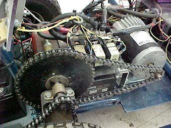
1. Introduction
        The Centurion II team of the Autonomous Ground Robotic (GRV) team of Bluefield
State College (BSC) presents Centurion II for the Intelligent Ground Vehicle Competition
(IGVC). The first Centurion robot competed in the 10th Annual IGVC. Centurion II differs from
Centurion in several vital areas as described in this report. In August, the GRV team decided to
split into two teams, in which the Centurion II team would concentrate on redesign and
improvement of our existing platform, while a new team, the Vasilius team, would concentrate on
a new platform. We made the decision to split into two teams because some of the lessons
learned from the 10th Annual IGVC involved improvements on Centurion and some of the lessons
learned could only be accomplished by starting over. The Centurion II team consists of six
undergraduates; some overlap exists with the Vasilius team members. We estimate 900 man-
hours were spent on Centurion II for the 2002-2003 academic year. Although we had a small
multi-departmental team, we know Centurion II will do well in all four competitions.

2. Design Process
        The first task the Centurion II team had on returning from the 10th Annual IGVC was to
decide on our design process for the upcoming year. Our approach was to review the methods
used by the previous first and second place design contest winners for the last three competitions,
compare these to other known methods, and choose one for us. We chose the five-stage design
process used by the United States Military Academy for MAGIC in 2001. This process is simple
yet powerful and adapts well to redesigning existing platforms such as ours. Figure 1 illustrates
the five stages of this process.

Identify the             Plan the             Develop               Generate                  Generate
   Need                  Process            Specification           Concept                   Product

 2.1 Identify the Need
        To identify the need all team members first reviewed the competition rules from the
previous competition. All team members then studied our list of notes and ideas generated from
Centurion’s competition experiences. Based on these studies we then listed concepts used in the
design of Centurion that needed changing. These changes include:
               •   Using an encoder for feedback control
               •   Moving the center of gravity back to improve traction and turning torque

                                                                                                  1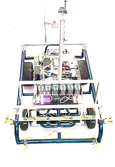
•   Totally rewriting the software for better reliability and completeness
              •   Changing the technique of object avoidance for improved reliability
              •   Making the vision less sensitive to light and dark transitions
              •   Designing and constructing a more suitable cover and camera mount
              •   Decreasing the width so navigation between obstacles would be easier
Our goal for the next 9 months was to “Develop a new Centurion capable of winning all four
competitions in the 11th Annual IGVC.” Our customer is the 11th Annual IGVC group of
judges and administrators.
2.2    Plan the Process
      In this stage of the design process we established the structure of the team and the types of
checks and balances to be employed to meet the needs identified. We divided the six-person
team into three sub-teams: the mechanical sub-team, the electrical sub-team, and the software
sub-team. An overall systems integrator served as the team’s leader.

In August, the team wrote a detailed schedule listing all the steps required to meet each of the
identified needs. Every team member then wrote a proposal due to the advisor on how he or she
would do the steps outlined by the whole team. Each week, every member had to write a
summary of the previous week’s accomplishments and what was planned for the following week.
Once a week the team met and discussed these summaries, updating when necessary. At the end
of each semester we presented our progress to the school and to sponsors.
 2.3 Develop Specifications
         We developed our specifications for each of the needs identified in Stage 1 using the
rules and regulations as our guideline. We decided on the following specifications:

                                                                                                 2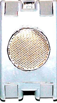
• Build an encoder with at least +/- 45 degree-range and 0.5 degree-resolution
• Move the center of gravity back at least five inches
• Rewrite the navigation code so pictures can be processed at least one per second
• Add proximity sensors that can sense up to two feet for reactionary mode
• Fix the vision to work in shade and sunlight
• Build a cover that would protect the electronics from rain and weigh < 10 pounds
• Decrease the width of the robot by at least 10 inches
The whole team developed each of these specifications, corresponding directly to the needs
identified in Stage 1.
2.4 Generate the Centurion II Concept
To meet each of the specifications listed above each sub-team, identified in Stage two,
researched conceptual design options and chose a concept. For example, to move the center of
gravity back we could have chosen any one of many concepts such as rebuilding the structure,
moving components around, or changing the wheel base. We chose to build a frame extension
and moved two batteries to the rear. In this stage we developed detailed plans using CAD for
each of these concepts. Details for this stage are available on request but are lengthy.
2.5 Generate the Centurion II Product
Each sub-team fabricated and tested all components based on the decisions from the
Concept stage. During the product generation stage, we also assessed safety, reliability, and
durability of each component. For example, we tested the remote E-Stop repeatedly on high and
low batteries and through obstacles both outside and in the building.
This final stage gave us a measure of how well we met the needs identified in the first
stage. All needs identified in Stage 1 were met according to the specifications given in Stage 3
except for one. Although we gave it a good effort, we could not get our rewritten software to
process pictures at one frame per second or faster. The reason for this is the limitation of the
single on-board computer and the amount of filtering and other processing we want to do on each
image. The result of this failure is that we have a slower robot. Next year we may install a
framegrabber, camera, and computer that are superior to the ones we now have.
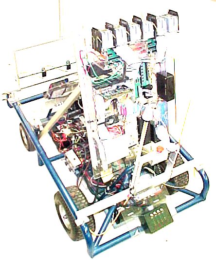
3. Centurion II Mechanical Design
3.1 Frame Design
One of our design process specifications from 2002 was to build a strong structure
capable of supporting all components over rough ground while keeping the total weight under
3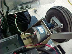
250 pounds. To meet this specification, we designed and built Centurion II using Lexan sheets
for support plates and shelving, and 0.125-inch square aluminum tubing for frames. Three
separate decks on Centurion II allowed us to place heavier components lower and lighter
components higher so that the center of gravity is low. We encircled the entire body with a
bumper for ease of lifting and to provide a mount for sensors.
          The lower deck is a steel plate serving as a strong base to the rest of the robot. This layer
is strong enough to hold all four 20-pound batteries, the main propulsion motor, the drive train
and gearing, two motor controllers and the steering motor. The middle deck contains the GPS
receiver, the encoder for steering, and two inverters.          The top deck holds the computer
components, sensor interface electronics, the sonars, and E-Stop electronics.
 3.2   Cover Design
                                                  One of the needs identified in our design process
                                         was to develop a new cover capable of protecting
                                         Centurion II’s electronics from rain while keeping the
                                         cover weight less than 10 pounds.           The mechanical
                                         engineering team members accomplished this by designing
                                         a Lexan-based curved top that directs the rain away from
the center of the robot. The Lexan top is strong enough to support the 20 pound payload/video
camera.
 3.3 Drive Motor
          Centurion is a one-wheel drive robot with a one-horsepower 24-volt DC motor. Our gear
analysis led us to use two sprockets in order to reduce the 3000-rpm motor to a 5 mph maximum
                                         robot ground speed. We have shown during analysis and
                                         testing that Centurion II has more than enough torque to
                                         start from a stall on a dry firm 15-degree positive slope. A
                                         problem arises when the robot runs through mud or wet
                                         thick grass as the Centurion team experienced in Orlando
                                         2002. For these conditions, we use a chain placed around
                                         the drive wheel.
 3.4 Steering Motor
          The steering motor is a linear stepper motor with
300-lbs of force designed to rotate a rod in or out a specified
number of revolutions. A worm gear translates this linear

                                                                                                     4
motion to steering. A motor controller interfaces the computer to the steering motor. Steering
commands from the navigation software specify turn angles, giving Centurion II the ability to
steer to a specified angle.
3.5 Sensor Placement
Centurion II has five sets of sensor concepts: vision, diffused visible, proximity, sonars,
and GPS. Vision consists of a camera mounted on a telescoping steel pole set in front of the
cover. We placed our four diffused visible sensors on the right and left front sides and on the
front, all connected to the bumper. The four proximity sensors are also fastened to the front
bumper. We mounted the sonars on the top layer of Lexan. The GPS antenna is located on the E-
Stop post on the rear of the robot.
4. Electronic Design
In this section we describe the electronic design of the power system, control system,
sensor system, emergency stop system, and computer system.
4.1 Power System
We designed the power system configuration for Centurion II so the robot would operate
on its own power for a minimum of 3 hours. Four Genesis Hawker Energy batteries powering
everything except sonars was the configuration we chose.
GPS
Battery #1 Battery #3 DC-AC
Main Converter Turn Motor
Motor 1
Control Battery #4
Battery #2 DC-AC Computer
Converter
2
Electronic/
Sensors
With this power system configuration we found the weakest link to be the computer battery,
lasting on the average about 3 hours without charging in the field. On-board circuitry charges the
batteries without the need for opening the robot. A 300-watt inverter connected to battery #3
5supplies power to the turn motor and another 350-watt inverter connected to battery #4 powers
the computer. A battery monitoring circuit placed in full view at the rear enables us to know how
much battery charge remains on each battery. The sonars have their own 6-volt batteries. These
batteries are a little larger than credit cards and are designed to handle a large pulsating current.
4.2 Control System
The control system consists of the main propulsion control and steering control. The
main propulsion control system uses a Curtis pulse-width-modulation MOSFET controller
connected to 100-amp contactors to control speed of the main propulsion motor. We connected a
main contactor between the 24 volts on the series-connected motor batteries and a 300-amp fuse.
A forward/reverse contactor pair allows us to switch polarity to the motor, thereby changing
directions between forward and reverse. Relays connected directly to the computer I/O board
interface the computer to the contactors. We use eight relays: one for main power, one for
forward motion, one for reverse motion, and five for speed control. One task for the main
propulsion control system design was to constrain the maximum speed to five miles per hour
while making sixteen speeds available to the programmer.
The steering control system controls and monitors the turn angle of the front wheels. One
of the needs we identified was an encoder, so we now have an encoder mounted directly on the
front axle. A vital task in steering control system design for the electrical team was to provide
just the right damping for maximally flat and stable control response.
Main
On/Off A
300A Contactor
Fuse Computer
Relay #2 F/R
Contactors
+ Computer
Relay #1 Computer
Battery #1 Relay #3
24VDC
+ Motor
Controller
Battery #2
E-Stop Remote Speed
Stop Computer
Control Relays 4-8
64.3 Sensor System
Centurion II has five sensor systems: vision, diffused visible, proximity, sonars, and GPS.
In this section we describe individually the electronic design of each of these systems. Later in
Section 5 we will describe the integration of all these sensors.
4.3.1 Electronic Design of Vision
Centurion II’s vision system consists of a web-cam and a
software capture control for visual basic that serves as a soft
framegrabber. Other than the camera and the USB connection,
no electronic design was needed.
4.3.2 Electronic Design of Diffused Visible Sensors
Four diffused visible sensors mounted on the front of Centurion II detect the presence of
pre-programmed colors such as white and yellow against the background of green and brown.
The purpose of the sensors is to detect road edges and potholes.
Another function of these sensors is to detect sand. Each
diffused visible sensor outputs zero volts for the “off” condition
and 12 volts for the “on” condition. The electronic design
needed for these sensors included developing an interface circuit
and cables. The sensor interface circuit connects the diffused
visible sensors to the computer input terminals. The circuit supplies 12 volts to the sensor and
reconditions the 12-volt sensor output to five volts for the computer input.
4.3.3 Electronic Design of Proximity Sensors
Four proximity sensors on the front detect the presence of objects from
zero to two feet away. These sensors detect any type of object regardless of
size, shape, or color.
Each proximity sensor has a relay that trips when the presence of an
object is detected. Electronic design for these sensors consisted of designing a
simple junction box connecting ground or five volts to the computer input
terminal. The junction box also supplies 12 volts to the sensors for power.
74.3.4 Electronic Design of Sonar Sensors
We have six sonar sensors mounted on the front of Centurion. The
purpose of the sonars is to detect and locate objects from two to 30 feet in front
of the robot.
Each sonar transmits a 40 KHz acoustic pulse and receives an echo if
the pulse strikes an object. For each sonar we had to design an electrical circuit
to convert the time difference between transmission and echo to an eight-bit
input to the computer input terminals. The decimal equivalent of this eight-bit
binary number is proportional to object distance. Our sonar circuit requires 5
volts for power while each sonar requires a special six-volt polapulse battery.
4.3.5 Electronic Design of GPS
Centurion II uses the Canadian Marconi Company GPS receiver that connects directly to
the computer serial port. No electronic design was required for this sensor.
4.4 E-Stop
As required by competition rules, Centurion II has both a manual E-Stop on the robot and
a remote E-Stop. These E-Stops connect in series to the propulsion motor controller as shown in
the diagram on the control system. In developing the
remote E-Stop we used code modulation so as not to have
interference from other robots or interfering emanations
from other sources such as computers and motors.
Centurion II also has a completely independent “kill” switch for safety.
4.5 Computer system
A 733 MHz Pentium III motherboard GPS
Steering
supplies the computational power for Centurion II. Motor Camera
Four 8255 peripheral interface integrated circuit Controller
Pentium III Wireless
chips allow the robot to control and monitor up to
Proximity Motherboard Network
96 inputs and outputs. Power for the motherboard
Sensors
comes from a standard computer power supply
96 I/O Sonars
attached to one of the two inverters. The diagram shows
how the sensors and control devices attach to the Diffused
Visible Main
motherboard. Sensors Motor
Controller
8An off board laptop connects to Centurion II through a wireless network. In this way, we
can operate and
test without having to physically touch the robot.
5. Software Design/Autonomous Algorithm
5.1 Design Objectives
As stated in the design process and in the competition requirements, design objectives for
our software design are:
• To develop an autonomous algorithm that processes images and does all long-
range planning computations at least once per second and does all short-range
reaction computations at least once per 10 milliseconds. We arrived at the “one
second” and “10 millisecond” specifications based on robot speed and size.
• To develop a software structure that can be easily maintained and accessed by
many different programmers.
• To write the most efficient program possible for performing all four major
autonomous functions and testing.
• To keep safety, reliability, and durability top priorities in software design
In order to meet these software design objectives we had to choose and optimally
integrate the sensor suite of Centurion II. First, we will describe this sensor integration.
5.2 Sensor Integration
The five sensors on Centurion II synergically integrate together to provide a broad range
of sensory input in order for the GRV to perform four major functions: lane following, object
detection, leader following, and waypoint navigation. We developed sensor integration on
Centurion using two complimentary ideas: long-range trajectory planning and short-range
reaction.
Camera Long-range trajectory planning Centurion II plans its trajectory
Sonars Long-range trajectory planning every one
Sensor Type Priority
GPS Long-range trajectory planning second
Diffused Visibles Highest
Diffused Visibles Short-range reaction using any
Proximity High
combinati
Proximity Sensors Short-range reaction
Sonars Medium
on of the
Camera Low
three planning sensors. If no errors occur in trajectory planning
and execution, then the robot will not need to use the reaction GPS Low
9sensors. In the event a reaction sensor detects a road edge or obstacle close to the robot, then the
robot responds to the reaction sensor. Once the reaction sensors are all clear then the robot will
go back to trajectory planning. Our testing has shown this concept works well. Many times
during testing we had to force errors in the planning process in order just to test the reaction
process. This philosophy is similar to how computers operate in both normal mode and interrupt
mode. Just as computers use priority levels in their interrupts, Centurion II uses a priority system
for the five sensors as illustrated in the table. Although Camera and GPS priorities are low, these
sensors are used all the time except during “interrupts” from the reaction sensors.
Centurion’s algorithm combines the information gathered from sonars and the camera to
produce a 3-D map of the course in front of the robot. This map shows lanes and obstacles from
six inches away to 30 feet away. The program transfers object distances as measured by the
sonars to the map produced from the camera information. In the next sections, we describe how
Centurion employs these concepts in sensor integration to perform the four major functions.
5.3 Lane Following and Obstacle Avoidance
Centurion II uses a trajectory planning process to plot the optimal path between lanes and
obstacles using the 3-D map produced from the fusion of camera and sonar information. We use
several methods of image processing: Sobel Amplitude and Canny edge detection, as well as
Binary Thresholding. Processing speed on Centurion is of utmost importance, therefore, instead
of analyzing each pixel of the map, we developed two other time-saving approaches we call the
“nine-line algorithm” and the “push algorithm”.
The “nine-line algorithm” determines the path that has the widest room between lanes
and obstacles on each of the nine equally-spaced horizontal lines (this divides the map into 10
equally-sized horizontal slices.) We found, given camera angle and field of view, the distance
between two consecutive lines was slightly smaller than the white pail, the smallest obstacle on
the course. The algorithm then establishes candidate paths with the most “elbow” room between
each horizontal line. Both maximum and minimum distances from obstacles and lanes are
allowed since one lane may be absent or dashed. The
robot turn angle and time of turn are a combination of past
and present paths creating a recursive-type algorithm.
The “push algorithm” divides the map into ten
regions on the left and ten regions on the right. The sum
of all pixel gray-scaled values in each region create an
obstacle/line “force” that pushes the robot away from the
region. Regions at the bottom of the map have more
Path
10weight than regions at the top. All these “forces” are summed and the robot takes the least
resistant path between them with a turn angle proportional to the resultant force.
5.4 Leader Following
The leader following algorithm operates in almost an inverted method as compared to
lane following/obstacle avoidance. Instead of avoiding lanes and obstacles, this algorithm tracks
an object. Using Binary Thresholding and a variant of the nine-line approach outlined above, we
turn the robot left and right so as to keep the object in the center of the image. The robot
maintains distance using a combination of camera and sonars. If the image moves toward the top
of the image, the robot increases speed, and vice versa. Sonar measurements taken in the center
front also give distance. At this time, the fusion of distance information is an average of sonar
and camera, but in the future we plan to develop a Kalman filter that optimally combines
measurements based on the dynamic model of the robot.
5.5 Waypoint Navigation
Centurion II’s waypoint navigation algorithm uses GPS and proximity sensors to navigate to
target points. This algorithm
has the structure as shown in
the insert. The GPS receiver
1. Input coordinates of Start and all Targets Centurion uses is neither
2. Find initial error between given and measured WAAS-enabled nor
Start position differential. However, we can
3. Start Centurion II in forward motion achieve five-foot accuracy by
4. Move to next target by comparing robot position subtracting initial errors
to next target position between given and measured
5. Monitor proximity sensors for obstacles positions at the Start. As long
6. If obstacle, stop, turn, go to Step 3 as the robot can finish the
7. Increase target number if target is found course in less than five
8. If target number is ten, then stop robot minutes, GPS errors should not
9. If target number < ten, go to Step 4 change much (see our analysis
in Section 6.)
116. Analysis of Predicted Performance and Results
Our research indicates Centurion should perform as indicated in the following table. The
table also indicates our results so far. A “*” symbol means we have not yet measured that
performance item. Each prediction listed in the table comes from analyses of components as well
as overall performance. For example, to analyze object detection we compared the theoretical
detection distance, pattern width, and pattern shape of the sonars to measurements. We did the
same for the proximity sensors. Both sonars and proximity sensors used together give us a full
detection range of two inches to 30 feet.
Performance Measure Performance Prediction Performance Results
Speed 5 mph 4.9 mph
Ramp Climbing 25-degree incline *
Turn Reaction Time 45 degrees/2 seconds 45 degrees/2 seconds
Battery Life 3 hours weakest link 3 hours weakest link
Stop Reaction Time Immediate Almost Immediate
Object Detection 0 inches to 32 feet 2 inches to 30 feet
Dead-Ends and Traps Chosen paths are clear *
Potholes Chosen paths are clear *
Waypoint Accuracy 5 feet one sigma 5-10 feet one sigma
7. Other Design Considerations
7.1 Safety, Reliability, and Durability
We kept safety top priority throughout this project. Some of our safety features include
the following:
• We use non-conductive Lexan with aluminum supports
• Besides both required E-Stops we have an independent “kill” switch
• On-board charger circuitry is separated from batteries
• Contactors and batteries are on opposite ends of the robot
• All components are mounted away from drive chain
• Plastic housings are used for all electrical circuits
• We never test Centurion II without at least 2 team members present
We have noticed the lack of reliability of many of the robots during past competitions.
Therefore, we have stressed the reliability of Centurion II. Redundancy is the tool we used to
achieve a higher level of reliability. As described in Software Design, different sensor groups
12have redundant functions. Both the camera and the diffused visible sensors detect the presence of
lanes. The camera algorithm also doubles with the sonars and proximity sensors in detecting
objects.
Switching from metal supports to all Lexan and Aluminum enhanced Centurion
II’s durability. Lexan is flexible enough to act to some degree as a shock absorber. As a
result, component vibration and bouncing are kept to a minimum.
7.2 Cost
The following table shows the cost of Centurion II’s component’s.
Item Actual Worth Our Cost
Stepper Controller $800 $800
Diffused Visibles $400 $400
Proximity Sensors $600 $100
Sonars $150 $150
GPS Receiver $600 $600
Propulsion Motor $250 $250
Main Motor Controller $250 $250
Steering Motor $200 $200
Steering Motor controller $750 $750
Motherboard $400 $400
Digital I/O $500 $500
Miscellaneous $600 $300
Not counting student and sponsor labor, Centurion II would cost a total of $5500 to replace. We
have spent approximately $4800 in parts and have received about $700 in donations.
13You can also read